Track pan
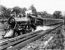
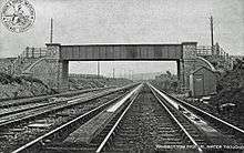
A track pan (American terminology) or water trough (British terminology) is a device to enable a steam railway locomotive to replenish its water supply while in motion. It consists of a long trough filled with water, lying between the rails. When a steam locomotive passes over the trough, a water scoop can be lowered, and the speed of forward motion forces water into the scoop, up the scoop pipe and into the tanks or locomotive tender.
Origin
Steam locomotives consume considerable volumes of water, and the tender or side tanks need to be replenished at intervals. Traditionally the engine water was replenished during station stops, but if it was desired to run long distances without stopping, the requirement to take water was a significant limitation. The Railway Magazine reported a development by John Ramsbottom:
| “ | In the year 1860 the London and North-Western Company having decided to accelerate the Irish mail [express train], Mr. Ramsbottom, then their chief mechanical engineer, was asked to make the run between Chester and Holyhead, 84¾ miles, in 2 hours 5 minutes... It was clear that if the usual stop on the road to take in water could be avoided, an important point would be gained; but there were no tenders of sufficient capacity to hold the quantity of water required to enable an engine to run through without stopping. In an ordinary way, from 1,800 to 1,900 gallons were consumed, but in the rough and stormy weather frequently experienced along the exposed coast of North Wales it was not unusual for the consumption to rise to 2,400 gallons; whilst the largest tenders only held 2,000 gallons.[1] | ” |
Ramsbottom arranged some experiments and showed that the forward motion of a scoop in a trough of water would force water up a connected pipe and into a tank. He calculated the quasi-static head produced by the forward motion:
| “ | …at a velocity of 15 miles an hour the water is lifted 7½ ft., this was exactly the result attained in practice by the apparatus; at this speed the water was raised to the top of the delivery pipe (7½ ft.), and was there maintained without running over into the tender whilst the scoop was in action. Again, theoretically the maximum amount of water the pipe was capable of raising was 1,148 gallons—5 tons—and this was reached when the engine was moving at the rate of about 80 miles an hour. The result of experiments made at different speeds was that at 22 miles an hour the delivery was 1,060 gallons; 33, 1,080; 41, 1,150; and 50, 1,070; showing that the quantity delivered varies very little at speeds above 22 miles an hour, which is accounted for by the shorter times the scoop is passing through the water.[1] | ” |
The track is raised a little over a short distance each end of the trough, so that the engine, and the scoop which may already be lowered, descend into the trough:
| “ | Many people think the scoop is let down into the water whilst the engine is passing over the trough, and has to be withdrawn immediately it readies the further end; but this method would not work, the time is too short. The scoop may be lowered at any distance before it arrives at the trough, and will run clear of everything until, by a very simple and ingenious arrangement, it dips automatically into the water to the required depth of 2in. The rails at each side of the trough are laid on a level slightly lower than the surface of the water, and as the engine descends to this level, the scoop, which is so adjusted that the lower edge is the same height as the rails, descends with it and becomes immersed in the water. To save lowering the line the whole distance, a short incline is made, rising to a height of about 6 in. at a point 16 yards from the commencement of the trough; the line then falls to the level it maintains until it reaches the further extremity of the trough, when there is again a slight rise which carries the scoop out of the water and clear of the end of the trough.[1] | ” |
The first installation was brought into use on 23 June 1860 at Mochdre, Conwy, on the North Wales main line of the London and North Western Railway (LNWR) about midway between Chester and Holyhead.[2][3][4]
The siting of the troughs requires a long enough length of straight and level track (although very large radius curves could be accommodated). There must be a good water supply nearby. In hard water areas, water softening plant may have been considered necessary.[2]
Locomotive equipment
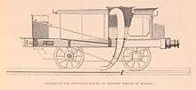
A scoop is fitted to the underside of the locomotive's tender (or the locomotive itself in the case of tank locomotives) in such a way that it can be raised or lowered, by a hand operated screw or a power mechanism. The scoop feeds into a vertical pipe that discharges into the water tank. The scoop is purposely made of light construction so that, should it strike an obstruction, it tears away causing no serious damage to the locomotive or its trailing vehicles. Tank locomotives on the Lancashire and Yorkshire Railway were equipped with double scoops, facing both forwards and backwards, to facilitate collection in either direction of travel.[5]
The scoop needs to be lowered at speed at the correct location – shortly before the start of the trough – and raised again when either the tank is full, or at the end of the trough. Lineside indicators are provided to assist engine crews in determining the location; in the UK it was a large white rectangular board with a black horizontal zigzag marking. On American railroads, illuminated trackside signals were employed for night-time usage, to indicate the start and approaching end of the track pan.
A 1934 report said that the LMS had carried out tests recently and introduced a deflector 1 ft. 4 in. ahead of the scoop to pile water in the centre of the trough, thus reducing spillage out of the troughs by about 400 gallons (about 20%) for each use.[6]
Venting on the tender needed to be free to allow a high rate of release of expelled air from the tank. Tank locomotives were generally fitted for picking up in either direction, but tender locomotives generally picked up in the forward direction only.[2]
Operational considerations
The LNWR quickly installed water troughs at other locations, but other companies were slow to adopt the new apparatus. The Great Western Railway did so from 1895, and subsequently all the major railways in Great Britain, with the exception of the lines south of the River Thames, installed the equipment.
Taking water at speed results in considerable spray behind the scoop; this risks drenching passengers in the leading vehicles, and in Great Britain it was customary for the guard or other traincrew to warn passengers in the first coach to keep the windows closed. In one incident on the LMS railway in Britain, two streamlined trains with "Coronation" class locomotives happened to pass each other at a water trough when one of the trains was taking on water. The other train suffered broken windows due to lumps of tender coal scattered by the spray and the complaints from drenched passengers caused the management to retimetable the trains to ensure this could not happen again. Vaughan says that the Royal Train when conveying royalty was not permitted to be passed by another train in a section where there was a water trough.[2]
Vaughan states that the GWR investigated the effectiveness of varying train speed, and found that 45 mph was the optimum speed; but water could be picked up successfully as low as 15 mph. At that speed 944 gallons could be picked up in 440 yards, but Vaughan suggests that this is a low theoretical figure, and that it overlooks the bow wave effect which enables a greater take-up rate. There was a significant resistance to the forward motion of the engine during the process, enough to require special care by the driver to avoid problems on unfitted freight trains.[2]
The considerable water spray made track maintenance difficult, and the physical trough equipment limited access for packing sleepers, exacerbating the problem. In very cold weather the water would freeze, preventing water pick-up, unless a heating apparatus was installed.
Track pans normally took a while to fill up after being used, so they could not be used immediately by a close-following train. They were also expensive to maintain, generally requiring a pumping station, a lot of plumbing, and an employee or two to maintain. They were thus only justified on a railroad with a high traffic volume. In the United States, several big eastern railroads used them, primarily the New York Central and Pennsylvania Railroad.
In Britain, they could be found on all main lines, except on the Southern Railway.[7][8][2][9][10] They were removed as use of steam trains decreased. When the Aber troughs were removed in 1967, the only remaining troughs were in north-west England and Scotland.[11]
Use by diesel locomotives
Diesel locomotives were introduced in the United Kingdom by British Railways in the 1950s, working alongside steam traction until 1968. Passenger vehicles were heated by steam from the locomotive boiler at that time, and the early diesel locomotives were provided with auxiliary boilers to provide the steam. Locomotives intended for long non-stop runs (such as the Class 40 and Class 55) were fitted with water scoops to allow them to replenish the steam generator's water supply from troughs/pans. The withdrawal of steam traction and the introduction of rolling stock with electric rather than steam heating removed the need for such equipment on later types and scoop-equipped locomotives had their scoops removed.
Locations
A map showing the location of GWR troughs in the 1930s is reproduced in the book 'The Great Western Railway'.[12] They are typically at spacings of 40 to 50 miles, but with some wide variations. There are a few instances of trough locations very close to major stopping points; for example Fox's Wood, near St Annes Park, two miles from Bristol Temple Meads; however this was installed when trains to South Wales travelled via Bath and Filton, using these troughs; after the opening of the South Wales direct route via Badminton, numerous passenger and goods trains continued to use the route and required the troughs. The lengths are also given: they vary from 524 to 620 yards (480 to 570 metres).
The locations were (in 1936):
| Location | Mileage | In use from | Length (yards) |
|---|---|---|---|
| Pangbourne - Goring | 43½ | 1 October 1895 | 620 |
| Aldermaston - Midgham | 45½ | by 1904 | 620 |
| Fairwood Junction (up) | 111½ | - | 553 |
| Fairwood Junction (down) | 111¾ | - | 495 |
| Cogload Jn - Creech Jn | 159¼ | March 1902 | 560 |
| Exminster - Starcross | 200 | July 1904 | 560 |
| Keynsham - Fox's Wood | 114¾ | 1 October 1895 | 620 |
| Chipping Sodbury | 104 | 1 January 1903 | 524 |
| Undy - Magor | 150¼ | - | 560 |
| Ferryside | 240¾ | - | 620 |
| Denham - Ruislip | 2¼ | 20 November 1905 | 560 |
| Kings Sutton | 81½ | - | 560 |
| Rowington Jn | 114½ | by July 1902 | 440 (560 from 1908) |
| Charlbury | 78 | - | 560 |
| Bromfield - Ludlow | 22½ | - | 613 |
| Lostwithiel | ? | - | ? |
Similar 1934 maps[14] showed troughs on the main East, Midland and West Coast routes from London to Scotland -
Kings Cross to Edinburgh Waverley
| Location | Mileage apart | Length (yards) |
|---|---|---|
| Langley - Stevenage | 27 | 694 |
| Peterborough - Werrington Jt | 52 | 638 |
| Muskham | 42 | 704 |
| Scrooby - Bawtry | 24 | 704 |
| Northallerton - Danby Wiske | 76 | 613 |
| Lucker - Berwick | 98 | 613 |
| Edinburgh | 73 |
London Euston to Edinburgh and Glasgow
| Location | Mileage apart | Length (yards) |
|---|---|---|
| Hatch End - Bushey | 15 | 505 |
| Wolverton - Castlethorpe | 38 | 559 |
| Rugby - Brinklow | 32 | 554 |
| Tamworth - Lichfield | 28 | 642 |
| Whitmore - Madeley | 36 | 563 |
| Preston Brook - Moore | 29 | 579 |
| Brock - Garstang | 40 | 561 |
| Hest Bank - Bolton-le-sands | 18 | 562 |
| Low Gill - Tebay | 26 | 553 |
| Floriston - Gretna | 45 | 560 |
| Thankerton - Carstairs | 64 | 557 |
| Glasgow | 32 | |
| Edinburgh | 31 |
London St Pancras to Glasgow
| Location | Mileage apart | Length (yards) |
|---|---|---|
| Oakley - Sharnbrook | 55 | 557 |
| Loughborough - Hathern (via Leicester) | 58 | 557 |
| Melton Mowbray (via Nottingham) | 45 | 557 |
| Dent - Hawes (see also Garsdale railway station) | 144 | 554 |
| Floriston - Gretna | 45 | 560 |
| Kirkconnel - New Cumnock | 58 | 564 |
| Glasgow | 49 |
Other British troughs are mentioned in articles on Ipswich and Tivetshall railway stations (Norfolk).
Continuous water trough supply
The Railway Magazine writer, quoted above, contemplated nearly-continuous water troughs, avoiding the transport of large quantities of water in the train:
The question has been discussed as to whether it would be possible to have a continuous supply of water all along the lines, and so obviate the necessity for tenders. Some years ago a writer in the "Engineer" put it in this way; One ton of coal will last a heavy goods train 40 miles, and an express nearly 100 miles; but from 6 to 8 or 9 tons of water are required for the same distance. If the tender were done away with, the coals, and a small tank with a capacity of forty or fifty gallons to receive the water, and from which to supply the boiler, would have to be carried on the engine. After allowing for these, 15 or 20 tons of paying load might be added to the train, which would be an advantage additional to the primary object—the saving of time.[1]
Alternative techniques
Railway companies were well aware of the cost of installing and maintaining this equipment, and the provision of tenders with a large water capacity was an alternative employed in some cases. The London and South Western Railway in England used large 8-wheel tenders nicknamed "water carts".
See also
References
- 1 2 3 4 Stoker, Gilbert J. (March 1901). "Locomotive Water Supply: Ramsbottom's Pick-Up Apparatus". The Railway Magazine. Vol. VIII no. 45. London, England.
- 1 2 3 4 5 6 Vaughan, Adrian (1990). "Water troughs on the GWR". Railway World. Vol. 51. pp. 278–80, 370–4.
- ↑ Robbins, Michael (1967). Points and Signals. London: George Allen & Unwin.
- ↑ Acworth, J. M. (1889). The Railways of England. London: John Murray.
- ↑ Tuplin, William (1963). North Western Steam. London: Allen & Unwin. p. 136. OCLC 504695570.
- ↑ "Water pick-up troughs". The Railway Magazine. Vol. 74 no. 439. January 1934. p. 5.
- ↑ Foster, Richard (1989). "L&NWR water troughs". British Railway Journal (London & Birmingham Railway edition): 84–91.
- ↑ Twells, H. N. (1982). LMS Miscellany: a pictorial record. Oxford: Oxford Publishing Co. ISBN 0-86093-172-2.
- ↑ "Water pick-up troughs". The Railway Magazine. Vol. 74 no. 439. January 1934. pp. 4–7.
- ↑ Webb, David (August 1984). "Water troughs". Cumbrian Railways Circular. 3: 223, 263–4.
- ↑ Modern Railways. July 1967. p. 397. Missing or empty
|title=(help) - ↑ Whitehouse, P; Thomas, David St John (eds.). The Great Western Railway - 150 Glorious Years. Newton Abbot: David & Charles. ISBN 0-7153-8763-4.
- ↑ Great Western Railway, General Appendix to the Rule Book, 1936, quoted by Vaughan; the Lostwithiel entry comes from H Holcroft, An Outline of Great Western Locomotive Practice, quoted by Vaughan
- ↑ "Water pick-up troughs". The Railway Magazine. Vol. 74 no. 439. January 1934. p. 7.