Signalling control
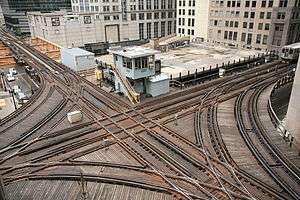
On a rail transport system, signalling control is the process by which control is exercised over train movements by way of railway signals and block systems to ensure that trains operate safely, over the correct route and to the proper timetable. Signalling control was originally exercised via a decentralised network of control points that were known by a variety of names including signal box (International and British), interlocking tower (North America) and signal cabin (some railways e.g., GCR). Currently these decentralised systems are being consolidated into wide scale signalling centres or dispatch offices. Whatever the form, signalling control provides an interface between the human signal operator and the lineside signalling equipment. The technical apparatus used to control switches (points), signals and block systems is called interlocking.
History
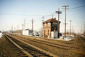
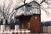
Originally, all signalling was done by mechanical means. Points and signals were operated locally from individual levers or handles, requiring the signalman to walk between the various pieces of equipment to set them in the required position for each train that passed. Before long, it was realised that control should be concentrated into one building, which came to be known as a signal box. The signal box provided a dry, climate controlled space for the complex interlocking mechanics and also the signalman. The raised design of most signal boxes (which gave rise to the term "tower" in North America) also provided the signalman with a good view of the railway under his control. The first use of a signal box was by the London and Croydon Railway in 1843 to control the junction to Bricklayers' Arms in London.[1]
With the practical development of electric power, the complexity of a signal box was no longer limited by the distance a mechanical lever could work a set of points or a semaphore signal via a direct physical connection (or the space required by such connections). Power operated switch points and signalling decides greatly expanded the territory that a single control point could operate from several hundred yards to several miles.[2] As the technology of electric relay logic was developed, it no longer became necessary for signalmen to operate control devices with any sort of mechanical logic at all. With the jump to all electronic logic, physical presence was no longer needed and the individual control points could be consolidated to increase system efficiency.
Another advancement made possible by the replacement of mechanical control by all electric systems was that the signalman's user interface could be enhanced to further improve productivity. The smaller size of electric toggles and push buttons put more functionality within reach of an individual signalman. Route-setting technology automated the setting of individual points and routes through busy junctions. Computerised video displays removed the physical interface altogether, replacing it with a point-and-click or touchscreen interface. Finally, the use of Automatic Route Setting removed the need for any human input at all as common train movements could be fully automated according to a schedule or other scripted logic.
Signal boxes also served as important communications hubs, connecting the disparate parts of a rail line and linking them together to allow the safe passage of trains. The first signalling systems were made possible by technology like the telegraph and block instrument that allowed adjacent signal boxes to communicate the status of a section of track. Later, the telephone put centralised dispatchers in contact with distant signal boxes and radio even allowed direct communication with the trains themselves. The ultimate ability for data to be transmitted over long distances has proven the demise of most local control signal boxes. Signalmen next to the track are no longer needed to serve as the eyes and ears of the signalling system. Track circuits transmit train locations to distant control centres and data links allow direct manipulation of the points and signals.
While some railway systems have more signal boxes than others, most future signalling projects will result in increasing amounts of centralised control relegating the lineside signal box to niche or heritage applications.
Naming
In any node-based control system, proper identification is critical to ensuring that messages are properly received by their intended recipients. As such, signalling control points are provided with names or identifiers that minimise the likelihood of confusion during communications. Popular naming techniques include using nearby geographic references, line milepost numbers, sequence numbers and identification codes. Geographic names can refer to a municipality or neighbourhood, a nearby road or geographic feature, local landmarks and industry which may provide the railway with traffic or railway features like yards, sidings or junctions.
On systems where Morse code was in use it was common to assign control locations short identification codes to aid in efficient communication, although wherever signalling control locations are more numerous than mileposts, sequence numbers and codes are more likely to be employed. Entire rail systems or political areas may adopt a common naming convention. In Central Europe, for example, signalling control points were all issued regionally unique location codes based roughly on the point's location and function,[3] while the American state of Texas sequentially numbered all interlockings for regulatory purposes.[4]
As signalling control centres are consolidated it can become necessary to differentiate between older style boxes and newer train control centres, where signalmen may have different duties and responsibilities. Moreover, the name of the signalling centre itself may not be employed operationally in preference to the name of individual signalling workstations. This is especially true when signalling centres control large amounts of territory spanning many diverse lines and geographical regions.
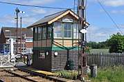
In most cases where the control locations are still in the field adjacent to railway tracks, the name or code of the control point is plainly labelled on the side of the signal box structure as an extra visual reminder to the train operators where they are. Moreover, wayside signals may also be equipped with identification plates that directly or indirectly indicate who controls that signal and that stretch of the line.
Control apparatus
For more information, see also Interlocking.
Lever frame
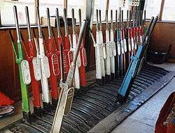
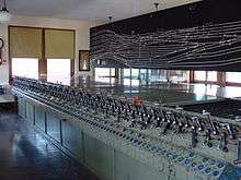
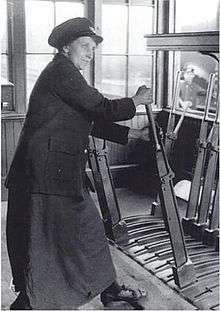
The earliest signal boxes housed mechanical lever frames. The frame was usually mounted on a beam beneath the operating floor. Interlocking was attached to the levers, which ensured that signals showed the correct indication with regard to the points and were operated in the right order. Wires or rods, connected at one end to the signals and points and at the other to levers in the signal box, ran alongside the railway.
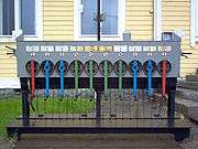
In many countries, levers are painted according to their function, e.g. red for stop signals and black for points, and are usually numbered, from left to right, for identification. In most cases, a diagram of the track and signalling layout is mounted above the lever frame, showing the relevant lever numbers adjacent to the signals and points.
Hand powered interlockings were referred to as armstrongs and hand throws in the United States.
Power frames have miniature levers and control the signals and points electrically. In some cases, the interlocking was still done mechanically, but in others, electric lever locks were used.
In a few cases, signals and points were operated pneumatically upon operation of the appropriate lever or slide.
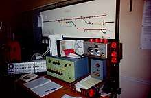
Control panel
In a signal box with a control panel, the levers are replaced by buttons or switches, usually appropriately positioned directly onto the track diagram. These buttons or switches are interfaced with an electrical or electronic interlocking. In the UK, control panels are of the following types:
- Individual function switch (IFS)
- A separate button/switch is provided for each signal and for each set of points. This type of panel is operated in a similar manner to a lever frame. The signalman must move each set of points to the desired position before operating the switch or button of the signal reading over them.
- This type of panel needs the least complex circuitry but is not suited to controlling large or busy areas.
- One control switch (OCS)
- A separate switch/button is provided for every signalled route. There will be as many switches/buttons per signal as there are routes (i.e. signalled destinations) from that signal. To set the desired route, the relevant switch or button is operated. All points within the route are automatically set to the required position.
- Individual points switches are provided, but they are normally left in the central position, which allows the points to be automatically set by the action of setting a route.
- Entrance-exit (NX)
- This type of panel has one switch/button provided for every signal (except that some panels have separate 'entrance' and 'exit' devices). To set a route, the signalman operates the device for the 'entrance' signal, followed by the device for the 'exit' (destination) signal. All points within the route are automatically set to the required position and, provided all the points are detected by the interlocking in the correct position, the entrance signal will clear.
- Individual points switches are provided, but they are normally left in the central position, which allows the points to be automatically set to the normal or reverse position by the action of setting a route.
Similar principles of operation as described above are applicable throughout the world.
Video display unit
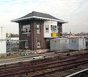
Modern signal boxes tend to be provided with VDU based, or similar, control systems. These systems are less expensive to build and easier to alter than a traditional panel. In the UK, large modern signal boxes are typically of the Integrated Electronic Control Centre type. Variations of these control systems are used throughout the world.
Present day

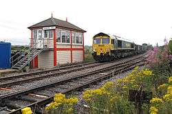
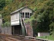
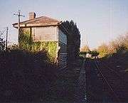
While rare, some traditional signal boxes can still be found. Some still control mechanical points and signals, although in many cases, the lever frame has been removed or is out of use, and a control panel or VDU has been installed. Most modern countries have little, if any, mechanical signalling remaining on the rail system. Both in the UK and Ireland, however, mechanical signalling is still relatively common away from the busiest lines; in Europe, there is also a considerable amount in Germany, Poland, and the Czech Republic. Traditional signal boxes can be found on many heritage railways.
The modern control centre has largely replaced widespread signal cabins. These centres, usually located near main railway stations, control the track network using electrical or electronic systems.
References
- ↑ Turner, J. T. Howard London Brighton and South Coast Railway, Part 1, Batsford, 1977 pp. 196-8
- ↑ Principles of Electric Locking by James Anderson
- ↑ "www.stellwerke.de - Liste Deutscher Stellwerke". www.stellwerke.de. Archived from the original on 1 October 2017. Retrieved 26 March 2018.
- ↑ "Archived copy". Archived from the original on 2012-01-25. Retrieved 2013-03-30.
Notes
- Kichenside, G. and Williams, A., (1998), Two Centuries of Railway Signalling, Oxford Publishing Co., ISBN 0-86093-541-8
- Vanns, M. A., (1995), Signalling in the Age of Steam, Ian Allan, ISBN 0-7110-2350-6
- John Armstrong, "All About Signals." Trains Magazine, July 1957.
Photo gallery
_(6587294579).jpg)