Overhead line
An overhead line or overhead wire is used to transmit electrical energy to trams, trolleybuses or trains. It is known variously as:
- Overhead contact system (OCS)
- Overhead line equipment (OLE or OHLE)
- Overhead equipment (OHE)
- Overhead wiring (OHW) or overhead lines (OHL)
- Catenary
- Trolley wire
- Traction wire
In this article, the generic term overhead line is used, as used by the International Union of Railways.[1]
An overhead line is designed on the principle of one or more overhead wires (or rails, particularly in tunnels) situated over rail tracks, raised to a high electrical potential by connection to feeder stations at regular intervals. The feeder stations are usually fed from a high-voltage electrical grid.
Overview
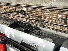
Electric trains that collect their current from overhead lines use a device such as a pantograph, bow collector or trolley pole. It presses against the underside of the lowest overhead wire, the contact wire. Current collectors are electrically conductive and allow current to flow through to the train or tram and back to the feeder station through the steel wheels on one or both running rails. Non-electric locomotives (such as diesels) may pass along these tracks without affecting the overhead line, although there may be difficulties with overhead clearance. Alternative electrical power transmission schemes for trains include third rail, ground-level power supply, batteries and electromagnetic induction.
Construction
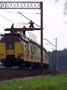
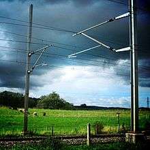
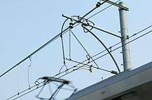
To achieve good high-speed current collection, it is necessary to keep the contact wire geometry within defined limits. This is usually achieved by supporting the contact wire from a second wire known as the messenger wire (in the US & Canada) or catenary (in the UK). This wire approximates the natural path of a wire strung between two points, a catenary curve, thus the use of "catenary" to describe this wire or sometimes the whole system. This wire is attached to the contact wire at regular intervals by vertical wires known as "droppers" or "drop wires". It is supported regularly at structures, by a pulley, link or clamp. The whole system is then subjected to mechanical tension.
As the contact wire makes contact with the pantograph, the carbon insert on top of the pantograph is worn down. The "straight" wire between the supports cause the contact wire to cross over the whole surface of the pantograph as the train travels around the curve, causing uniform wear and avoiding any notches. On straight track, the contact wire is zigzagged slightly to the left and right of the centre at each successive support so that the pantograph wears evenly. The movement of the contact wire across the head of the pantograph is called the 'sweep'.
The zigzagging of the overhead line is not required for trolley poles.
Depot areas tend to have only a single wire and are known as "simple equipment" or "trolley wire". When overhead line systems were first conceived, good current collection was possible only at low speeds, using a single wire. To enable higher speeds, two additional types of equipment were developed:
- Stitched equipment uses an additional wire at each support structure, terminated on either side of the messenger/catenary wire.
- Compound equipment uses a second support wire, known as the "auxiliary", between the messenger/catenary wire and the contact wire. Droppers support the auxiliary from the messenger wire, while additional droppers support the contact wire from the auxiliary. The auxiliary wire can be of a more conductive but less wear-resistant metal, increasing transmission efficiency.
Dropper wires traditionally provide physical support of the contact wire without joining the catenary and contact wires electrically. Modern systems use current-carrying droppers, which eliminate the need for separate wires.
The present transmission system originated about 100 years ago. A simpler system was proposed in the 1970s by the Pirelli Construction Co, consisting of a single wire embedded at each support for 2.5 metres (8 ft 2 in) of its length in a clipped, extruded aluminum beam with the wire contact face exposed. A somewhat higher tension than used before clipping the beam yielded a deflected profile for the wire that could be easily handled at 250 miles per hour (400 km/h) by a pneumatic servo pantograph with only 3 G accelerations.
For tramways a contact wire without a messenger wire is used.
Parallel overhead lines
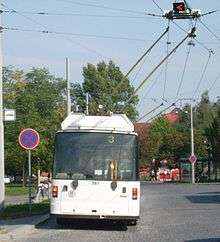
An electrical circuit requires at least two conductors. Trams and railways use the overhead line as one side of the circuit and the steel rails as the other side of the circuit. For a trolleybus no rails are available for the return current—the vehicles use rubber tyres on the road surface. Trolleybuses use a second parallel overhead line for the return, and two trolley-poles, one contacting each overhead wire. The circuit is completed by using both wires. Parallel overhead wires are also used on the rare railways with three-phase AC railway electrification.
Tensioning
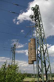
Catenary wires are kept in mechanical tension because the pantograph causes mechanical oscillations in the wire and the wave must travel faster than the train to avoid producing standing waves that would cause wire breakage. Tensioning the line makes waves travel faster.
For medium and high speeds, the wires are generally tensioned by weights or occasionally by hydraulic tensioners. Either method is known as "auto-tensioning" (AT) or "constant tension" and ensures that the tension is virtually independent of temperature. Tensions are typically between 9 and 20 kN (2,000 and 4,500 lbf) per wire. Where weights are used, they slide up and down on a rod or tube attached to the mast, to prevent them from swaying.
For low speeds and in tunnels where temperatures are constant, fixed termination (FT) equipment may be used, with the wires terminated directly on structures at each end of the overhead line. The tension is generally about 10 kN (2,200 lbf). This type of equipment sags on hot days and is taut on cold days.
With AT the continuous length of overhead line is limited due to the change in the position of the weights with temperature as the overhead line expands and contracts. This movement is proportional to the tension length, the distance between anchors. Tension length has a maximum. For most 25 kV OHL equipment in the UK, the maximum tension length is 1970m.
An additional issue with AT equipment is that, if balance weights are attached to both ends, the whole tension length is free to move along the track. To avoid this a midpoint anchor (MPA), close to the centre of the tension length, restricts movement of the messenger/catenary wire by anchoring it; the contact wire and its suspension hangers can move only within the constraints of the MPA. MPAs are sometimes fixed to low bridges, otherwise anchored to vertical catenary poles or portal catenary supports. A tension length can be seen as a fixed centre point, with the two half tension lengths expanding and contracting with temperature.
Most systems include a brake to stop the wires from unravelling completely if a wire breaks or tension is lost. German systems usually use a single large tensioning pulley (basically a ratchet mechanism) with a toothed rim, mounted on an arm hinged to the mast. Normally the downward pull of the weights and the reactive upward pull of the tensioned wires lifts the pulley so its teeth are well clear of a stop on the mast. The pulley can turn freely while the weights move up or down as the wires contract or expand. If tension is lost the pulley falls back toward the mast, and one of its teeth jams against the stop. This stops further rotation, limits the damage, and keeps the undamaged part of the wire intact until it can be repaired. Other systems use various braking mechanisms, usually with multiple smaller pulleys in a block and tackle arrangement.
Breaks
Lines are divided into sections to limit the scope of an outage and to allow maintenance.
Section break
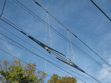
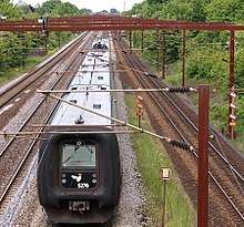
To allow maintenance to the overhead line without having to turn off the entire system, the line is broken into electrically separated portions known as "sections". Sections often correspond with tension lengths. The transition from section to section is known as a "section break" and is set up so that the vehicle's pantograph is in continuous contact with the wire.
For bow collectors and pantographs, this is done by having two contact wires run side by side over the length of 3 or 4 wire supports. A new one drops down and the old one rises up, allowing the pantograph to smoothly transfer from one to the other. The two wires do not touch (although the bow collector/pantograph is briefly in contact with both wires). In normal service, the two sections are electrically connected (to different substations if at or near the halfway mark between them) but this can be interrupted for servicing.
On overhead wires designed for trolley poles this is done by having a neutral section between the wires, requiring an insulator. The driver of the tram or trolleybus must turn off the power when the trolley pole passes through, to prevent arc damage to the insulator.
Pantograph-equipped locomotives must not run through a section break when one side is de-energized. The locomotive would become trapped, but as it passes the section break the pantograph briefly shorts the two catenary lines. If the opposite line is de-energized, this voltage transient may trip supply breakers. If the line is under maintenance, injury may occur as the catenary is suddenly energized. Even if the catenary is properly grounded, the arc generated across the pantograph can damage the pantograph, the catenary insulator or both.
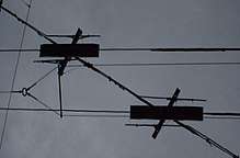
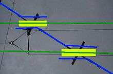
Neutral section (phase break)
Sometimes on a larger electrified railway, tramway or trolleybus system it is necessary to power different areas of track from different power grids, without guaranteeing synchronisation of the phases. (Sometimes the sections are powered with different voltages or frequencies.) The grids may be synchronised on a normal basis, but events may interrupt synchronisation. This is not a problem for DC systems, but for AC systems it is highly undesirable to connect unsynchronised grids. A simple section break is insufficient to guard against this as the pantograph briefly connects both sections.
A neutral section or phase break is used, consisting of two section breaks back-to-back with a short section of line that belongs to neither grid. If the two grids are synchronised this stretch of line is energised (by either supply) and trains run through it normally. If the two supplies are not synchronised it is disconnected from the supplies, leaving it electrically dead, isolating the two grids.
In countries such as France, South Africa and the United Kingdom, a pair of permanent magnets beside the rails at either side of the neutral section operate a bogie-mounted transducer on the train which causes a large electrical circuit-breaker to open and close when the locomotive or the pantograph vehicle of a multiple unit passes over them.[2] In the United Kingdom AWS equipment is used, but with reversed polarity. Lineside signs on the approach to the neutral section warn the driver to shut off traction power and coast through the dead section.
On the Pennsylvania Railroad, phase breaks were indicated by a position light signal face with all eight radial positions with lenses and no center light. When the phase break was active (the catenary sections out of phase), all lights were lit. The position light signal aspect was originally devised by the Pennsylvania Railroad and was continued by Amtrak and adopted by Metro North. Metal signs were hung from the catenary supports with the letters "PB" created by a pattern of drilled holes.
Dead section
A special category of phase break was developed in America, primarily by the Pennsylvania Railroad. Since its traction power network was centrally supplied and only segmented by abnormal conditions, normal phase breaks were generally not active. Phase breaks that were always activated were known as "Dead Sections": they were often used to separate power systems (for example, the Hell's Gate Bridge boundary between Amtrak and Metro North's electrifications) that would never be in-phase. Since a dead section is always dead, no special signal aspect was developed to warn drivers of its presence, and a metal sign with "DS" in drilled-hole letters was hung from the catenary supports.
Gaps
Occasionally gaps may be present in the overhead lines, when switching from one voltage to another or to provide clearance for ships at moveable bridges, as a cheaper alternative for moveable overhead power rails. Electric trains coast across the gaps. To prevent arcing, power must be switched off before reaching the gap. Usually the pantograph must be lowered too.
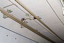
Overhead conductor rails

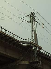
Given limited clearance such as in tunnels, the overhead wire may be replaced by a rigid overhead rail. An early example was in the tunnels of the Baltimore Belt Line, where a ∏ section bar (fabricated from three strips of iron and mounted on wood) was used, with the brass contact running inside the groove.[3] When the overhead line was raised in the Simplon Tunnel to accommodate taller rolling stock, a rail was used. A rigid overhead rail may also be used in places where tensioning the wires is impractical, for example on moveable bridges.
In a movable bridge that uses a rigid overhead rail, there is a need to transition from the catenary wire system into an overhead conductor rail at the bridge portal (the last post before the movable bridge). For example, the power supply can be done through a catenary wire system near a swing bridge. The catenary wire typically comprises messenger wire (also called catenary wire) and a contact wire where it meets the pantograph. The messenger wire is terminated at the portal, while the contact wire runs into the overhead conductor rail profile at the transition end section before it is terminated at the portal. There is a gap between the overhead conductor rail at the transition end section and the overhead conductor rail that runs across the entire span of the swing bridge. The gap is required for the swing bridge to be opened and closed. To connect the conductor rails together when the bridge is closed, there is another conductor rail section called "rotary overlap" that is equipped with a motor. When the bridge is fully closed, the motor of the rotary overlap is operated to turn it from a tilted position into the horizontal position, connecting the conductor rails at the transition end section and the bridge together to supply power.[4]
Short overhead conductor rails are installed at tram stops as for the Combino Supra.[5]
Crossings
Trams draw their power from a single overhead wire at about 500 to 750 V. Trolleybuses draw from two overhead wires at a similar voltage, and at least one of the trolleybus wires must be insulated from tram wires. This is usually done by the trolleybus wires running continuously through the crossing, with the tram conductors a few centimetres lower. Close to the junction on each side, the tram wire turns into a solid bar running parallel to the trolleybus wires for about half a metre. Another bar similarly angled at its ends is hung between the trolleybus wires, electrically connected above to the tram wire. The tram's pantograph bridges the gap between the different conductors, providing it with a continuous pickup.
Where the tram wire crosses, the trolleybus wires are protected by an inverted trough of insulating material extending 20 or 30 mm (0.79 or 1.18 in) below.
Until 1946, a level crossing in Stockholm, Sweden connected the railway south of Stockholm Central Station and a tramway. The tramway operated on 600-700 V DC and the railway on 15 kV AC. In the Swiss village of Oberentfelden, the WSB tramway operating at 750 V DC crosses the SBB line at 15 kV AC; there used to be a similar crossing between the WSB and the SBB at Suhr, this has been replaced by an underpass in 2010. Some crossings between tramway/light rail and railways are extant in Germany. In Zürich, Switzerland, VBZ trolleybus line 32 has a level crossing with the 1,200 V DC Uetliberg railway line; at many places, trolleybus lines cross the tramway. In some cities, trolleybuses and trams shared a positive (feed) wire. In such cases, a normal trolleybus frog can be used.
Alternatively, section breaks can be sited at the crossing point, so that the crossing is electrically dead.
Australia
Many cities had trams and trolleybuses using trolley poles. They used insulated crossovers, which required tram drivers to put the controller into neutral and coast through. Trolleybus drivers had to either lift off the accelerator or switch to auxiliary power.
In Melbourne, Victoria, tram drivers put the controller into neutral and coast through section insulators, indicated by insulator markings between the rails.
Melbourne has three level crossings between electrified suburban railways and tram lines. They have mechanical switching arrangements (changeover switch) to switch the 1,500V DC overhead of the railway and the 650V DC of the trams, called a Tram Square.[6] Proposals have been advanced to grade separate these crossings or divert the tram routes.
Greece
Athens has two crossings of tram and trolleybus wires, at Vas. Amalias Avenue and Vas. Olgas Avenue, and at Ardittou Street and Athanasiou Diakou Street. They use the above-mentioned solution.
Italy
In Rome, at the crossing between viale Regina Margherita and via Nomentana, tram and trolleybus lines cross: tram on viale Regina Margherita and trolleybus on via Nomentana. The crossing is orthogonal, therefore the typical arrangement was not available.
In Milan, most tram lines cross its circular trolleybus line once or twice. Trolleybus and tram wires run parallel in streets such as viale Stelvio and viale Tibaldi.
Multiple overhead lines
Some railways used two or three overhead lines, usually to carry three-phase current. This is used only on the Gornergrat Railway and Jungfrau Railway in Switzerland, the Petit train de la Rhune in France, and the Corcovado Rack Railway in Brazil. Until 1976, it was widely used in Italy. On these railways, the two conductors are used for two different phases of the three-phase AC, while the rail was used for the third phase. The neutral was not used.
Some three-phase AC railways used three overhead wires. These were an experimental railway line of Siemens in Berlin-Lichtenberg in 1898 (length 1.8 kilometres), the military railway between Marienfelde and Zossen between 1901 and 1904 (length 23.4 kilometres) and an 800-metre-long section of a coal railway near Cologne between 1940 and 1949.
On DC systems, bipolar overhead lines were sometimes used to avoid galvanic corrosion of metallic parts near the railway, such as on the Chemin de fer de la Mure.
All systems with multiple overhead lines have high risk of short circuits at switches and therefore tend to be impractical in use, especially when high voltages are used or when trains run through the points at high speed.
The Sihltal Zürich Uetliberg Bahn has two lines with different electrification. To be able to use different electric systems on shared tracks, the Sihltal line has its overhead wire right above the train, whilst the Uetliberg line has its overhead wire off to one side.
Overhead catenary

A catenary is a system of overhead wires used to supply electricity to a locomotive, tram (streetcar), or light rail vehicle that is equipped with a pantograph.
Unlike simple overhead wires, in which the uninsulated wire is attached by clamps to closely spaced crosswires supported by poles, catenary systems use at least two wires. The catenary or messenger wire is hung at a specific tension between line structures, and a second wire is held in tension by the messenger wire, attached to it at frequent intervals by clamps and connecting wires known as droppers. The second wire is straight and level, parallel to the rail track, suspended over it as the roadway of a suspension bridge is over water.
Catenary systems are suited to high-speed operations whereas simple wire systems, which are less expensive to build and maintain, are common on light rail or tram (streetcar) lines, especially on city streets. Such vehicles can be fitted with either a pantograph or trolley pole.
The Northeast Corridor in the United States has catenary over the 600 miles (1000 km) between Boston, Massachusetts and Washington, D.C. for Amtrak's higher-speed Acela Express and other trains. Commuter rail agencies including MARC, SEPTA, NJ Transit, and Metro-North Railroad utilize the catenary to provide local service.
In Cleveland, Ohio the interurban/light rail lines and the heavy rail line use the same overhead wires, due to a city ordinance intended to limit air pollution from the large number of steam trains passing through Cleveland between the east coast and Chicago. Trains switched from steam to electric locomotives at the Collinwood Rail Yards about 10 miles (16 km) east of Downtown and at Linndale on the west side. When Cleveland constructed its rapid transit (heavy rail) line between the airport, Downtown and beyond it employed a similar catenary, using electrification equipment left over after railroads switched from steam to diesel. Light and heavy rail share trackage for about 3 miles (4.8 km) along the Cleveland Hopkins International Airport Red (heavy rail) line, Blue and Green interurban/light rail lines between Cleveland Union Terminal and just past East 55th Street station, where the lines separate.
Part of the Boston, Massachusetts Blue Line through the northeast suburbs uses overhead lines, as does the Green Line.
Height
The height of overhead wiring can create hazards at level crossings, where it may be struck by road vehicles. Warning signs are placed on the approaches, advising drivers of the maximum safe height.
The wiring in most countries is too low to allow double stack container trains. The Channel Tunnel has an extended height overhead line to accommodate double-height car and truck transporters. India is proposing a network of freight-only lines that would be electrified with extra height wiring and pantographs.
Problems with overhead equipment
Overhead line equipment can be adversely affected by strong winds causing wires to swing.[7] Power storms can knock the power out with lightning strikes on systems with overhead wires, stopping trains following a power surge.
During cold or frosty weather, ice may coat overhead lines. This can result in poor electrical contact between the collector and the overhead line, resulting in electrical arcing and power surges.[8]
Overhead line equipment may require reconstruction of bridges to provide safe electrical clearance.
Overhead equipment, like most electrified systems, requires a greater capital expenditure when building the system than an equivalent non-electric system. While a conventional rail line requires only the grade, ballast, ties and rails, an overhead system also requires a complex system of support structures, lines, insulators, power-control systems and power lines, all of which require maintenance. This makes non-electrical systems more attractive in the short term, although electrical systems can pay for themselves eventually. Also, the added construction and maintenance cost-per-mile makes overhead systems less attractive on long-distance railways, such as those found in North America, where the distances between cities are typically far greater than in Europe. Such long lines require enormous investment in overhead line equipment, and major difficulties confront energizing long portions of overhead wire on a permanent basis, especially in areas where energy demand already outstrips supply.
Many people consider overhead lines to be "visual pollution", due to the many support structures and complicated system of wires and cables that fill the air. Such considerations have driven the move towards replacing overhead power and communications lines with buried cables.
History
The first tram with overhead lines was presented by Werner von Siemens at the International Electric Exposition in Paris 1881: the installation was removed after that event. In October 1883, the first permanent tram service with overhead lines was on the Mödling and Hinterbrühl Tram in Austria. The trams had bipolar overhead lines, consisting of two U-pipes, in which the pantographs hung and ran like shuttles. In April to June 1882, Siemens had tested a similar system on his Electromote, an early percursor of the trolleybus.
Much simpler and more functional was an overhead wire in combination with a pantograph borne by the vehicle and pressed at the line from below. This system, for rail traffic with a unipolar line, was invented by Frank J. Sprague in 1888. From 1889 it was used at the Richmond Union Passenger Railway in Richmond, Virginia, pioneering electric traction.
See also
References
- ↑ UIC English/French/German Thesaurus.
- ↑ "Vortok Automatic Power Control Magnet". Retrieved 25 July 2018.
- 1 2 "A ninety-six ton electric locomotive". Scientific American. New York. 10 August 1895.
- ↑ Cox, Stephen G.; Nünlist, Felix; Marti, Reto (25 September 2000). Electrification of swing and bascule bridges with overhead conductor rails (PDF). Northend Electrification Project. pp. 3–4. Retrieved 25 June 2018.
- ↑ Siemens press release
- ↑ TMSV: Tramway level crossings in Victoria
- ↑ "Kamerasystem skal advare lokoførere mod svingende køreledninger på Storebælt" (in Danish). 5 November 2013. Retrieved 25 June 2016.
- ↑ Stewart, Matt (21 May 2012). "Matangi trains 'more susceptible' to frost". The Dominion Post. Wellington. Retrieved 2 September 2015.
Further reading
- Cooper, B.K. (February–March 1982). "Catenaries and Contact Wires". Rail Enthusiast. EMAP National Publications. pp. 14–16. ISSN 0262-561X. OCLC 49957965.
External links
| Wikimedia Commons has media related to Overhead lines. |
- "Overhead Equipment - Neutral Section | RailElectrica". www.railelectrica.com. Retrieved 2018-03-06.
- "[IRFCA] Indian Railways FAQ: Electric Traction - I". irfca.org. Retrieved 2018-03-06.