SECU-3

SECU-3[1] is an internal combustion engine control unit. Open source project (drawings, schematic diagrams, source code etc. are open). Anyone can take part in the project and can access all information without registration.
Device controls the ignition, fuel injection and various other actuators of the internal combustion engine (ICE) and vehicle. In particular, it is capable of controlling the carburetor's choke using a stepper motor (auto choke), thus controlling RPM when engine is warming up. Manages AFR on the carburetor (like AXTEC AFR systems), idle cut off and power valve on carburetor, electric fuel pump, stepper gas valve with oxygen sensor loopback etc. Unique opportunities for reassigning the I/O functions. Smooth speed control of the cooling fan motor. The ability to edit the main settings and maps in real time (when engine is running) and switching between 2 or 4 sets of maps. And other features and functions (see below).
Currently, there are five modifications of the unit:
- SECU-3. The first version of the unit developed in 2007, controls ignition, cooling fan and some other functions. In the latest software releases, support for this unit has stopped. History of the SECU-3 versions with photos is here
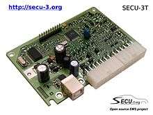
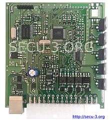
- SECU-3T.[2] It can control the ignition and fuel injection. It does not contain built-in power drivers for ignition coils, fuel injectors and idling air control (IAC) valve. It is necessary to use external drivers.
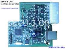
- SECU-3L.[3] It designed for ignition control only and it can be viewed as a lightweight version of the SECU-3T unit. It contains built-in drivers for ignition coils and manifold absolute pressure (MAP) sensor. It is fully software compatible with SECU-3T unit.
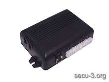
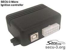
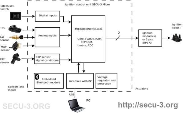
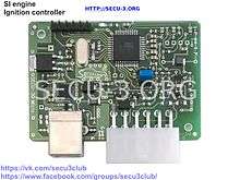
- SECU-3 Micro.[4] Very simple and budgetary ignition controller unit in small plastic enclosure. Has only few inputs and outputs and doesn't contain built-in power drivers for ignition coils. It is the simplest SECU-3 unit.
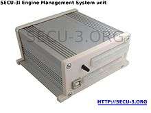
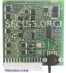
- SECU-3i.[5] Full-featured, complete engine management system in metallic enclosure with integrated power drivers (for ignition coils, injectors, IAC actuator etc.), extended number of I/O and Bluetooth. The latest author's development. This unit has two boards design.
Device performed on the 8-bit AVR microcontroller ATMega644, with 64kB memory (ROM), 4kB random access memory (RAM), and operates at a clock frequency of 20 MHz. It includes analog and digital inputs, chip for preprocessing signal from the knock sensor (KS) (except SECU-3 Lite and Micro units), a signal conditioner for reference VR sensor (except SECU-3 Micro unit), a signal conditioner for the crankshaft position (CKP) sensor, interface with a computer and outputs for actuators control.
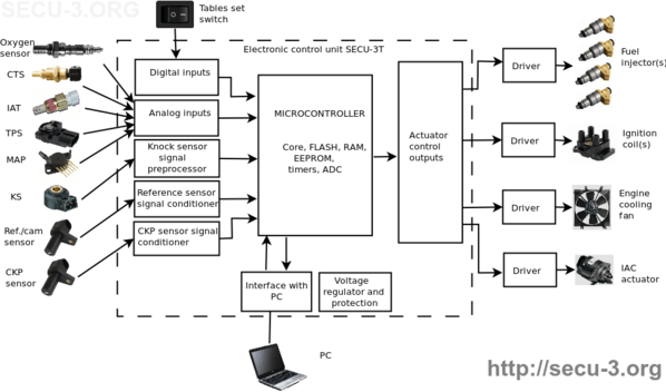
Structural diagram of the system with SECU-3T unit:
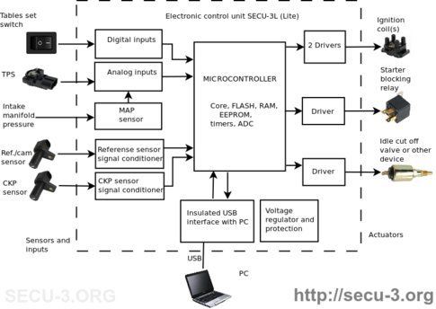

Structural diagram of the system with SECU-3L unit is shown on the following picture:
Structural diagram of the system with SECU-3 Micro unit:
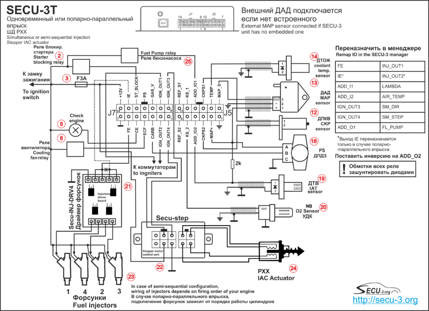
Example of wiring diagram of the SECU-3T unit for controlling of simultaneous or semi-sequential fuel injection on the 4-cylinder engine is shown on the picture below. Hi-z injectors and stepper IAC valve are used. On the right side of picture we can see external connector functions which should be remapped to specified values. It is done in the SECU-3 Manager software.
History
The first version of SECU-3 was launched in October 2007 and successfully works on the author's (A.Shabelnikov) vehicle for now. Since then, the project has received a lot of new features and synchronization methods. First discussing of the project was started in 2007 in one topic on the iXBT conference.[6] Since Dec. 2010 discussion moved to the forum on diyefi.org.[7] In 2013 own project's forum had been opened.[8] The system has evolved from the ignition control to the engine management system (ECU). The project is supported by author all the time.
Current status
Continue to develop and extend fuel injection features and algorithms (inter alia, full-sequential injection support). Also, author works on software for the SECU-3i unit.
Features of the current firmware related to fuel injection:
- Simultaneous (all injectors open at the same time), central (throttle-body) injection, two banks alternating (two injectors or two banks of injectors fire alternately) and semi-sequential injection (injectors fire by pairs). In the nearest future full-sequential injection support will be added
- Speed-density method of estimating airflow into an engine (MAP and IAT sensors are used)
- Open-loop IAC (closed-loop algorithm (PID) will be implemented in the nearest future)
- Closed loop control of AFR using oxygen sensor. Ability to set voltage threshold, integrator step etc.
- Tables: VE, AFR, inj.open time, warm up enrichment, IAC position on cranking, IAC position vs coolant temperature, inj.time on cranking, inj.timing
- After start enrichment
- Acceleration enrichment (TPS, RPM)
- Priming pulse (wetting of intake manifold) vs coolant temperature
License
GPL, TAPR OHL with one addition: developments can not be used in commercial purposes without written approval of author (according to information from the official site).
Features
- Support of engines with number of cylinders: 1,2,3,4,5,6,8
- Synchronization from CKP sensor and missing tooth wheel or from two sensors and non-missing tooth wheel. Support of 60-2, 36-1 and other wheels with different number of teeth (from 16 to 200)
- Synchronization from Hall sensor (you can leave distributor)
- Advance angle regulation from engine speed (from 1 VR sensor, 2 VR sensors or Hall sensor)
- Advance angle regulation from engine load (from MAP sensor)
- Correction of advance angle depending on temperature (various types of coolant temperature sensors)
- Correction of advance angle from detonation (from 1 or 2 knock sensors)
- Measurement of board voltage
- Idle cut-off valve solenoid control
- Control of power valve solenoid (part load enrichment valve)
- Multichannel output (from 1 up to 6 igniters). It is possible to use up to 8 channels!
- Support of 2 channel igniters (single input driven by both edges)
- RS-232 interface for reprogramming, control and tuning (with optical isolation) or USB interface (without optical isolation)
- Able to control of engine cooling fan (using of PWM is also supported)
- Starter blocking when engine speed reaches specified value
- Gas equipment support (automatic switch gas/gasoline)
- Output for error indication “Check Engine” with support of blink codes
- Ability to emergency start of boot loader
- Ability to recover settings in emergency case
- Idle speed regulation using advance angle
- Control of coil’s energy accumulation (dwell control)
- Cam sensor support (coil per cylinder – full sequential ignition)
- Fuel injection control (central, simultaneous injection)
- Injection timing control using map
- Calculation of air flow using Speed-Density method
- AFR control on carburetor(Solex) by means of valve actuators with closed loop (oxygen sensor)
Additional features:
- Control of an electric fuel pump
- Tunable pulses output for Hall sensor or tachometer
- Embedded stroboscope function (it is possible to use any free output)
- Output and input functions remapping
- Determine throttle gate position by TPS sensor
- Processing and writing to log file signals from 2 additional inputs (e.g. Oxygen sensor can be connected)
- Power management (ability of some functions to work after ignition is switched off, for instance working off cooling fan or auto choke control)
- Carburetor choke control (using a stepper motor)
- Stepper gas valve control
- Support of speed sensor (Displaying and writing to log vehicle speed (km/h) and passed distance (km))
- Control of manifold heater (also known as grid and intake heaters)
- Correction of advance angle using air temperature sensor (connected to one of 2 additional inputs)
- 3 versatile programmable outputs, which can be programmed by user to perform different actions in very convenient and flexible way
Version differences
| SECU-3 | SECU-3T | SECU-3T revC and later | SECU-3L (Lite) | SECU-3 Micro | SECU-3i | |
|---|---|---|---|---|---|---|
| Date | 2007 | 2012 | 2014 | 2015 | 2016 | 2016 |
| MCU | ATmega16, ATMega32 | ATMega32 | ATMega644 | ATMega644 | ATMega644 | ATMega644 |
| Features | Wasted spark, synchronization from CKP sensor | full-sequential ignition,
synchronization from Hall sensor, CKP sensor, CKP + reference sensor, automatic control of carburetor's choke, immobilizer with iButton key, optional embedded bluetooth |
same, plus fuel injection control,
AFR control on carburetor, stepper gas valve control, programmable outputs |
Lite version, intended for ignition control and two additional outputs.
Simplified installation and wiring. Ignition coil drivers integrated to the unit. |
Maximum simplified version, intended only for ignition control. Has only two ignition outputs and several inputs.
Simplified installation and wiring. |
The most functional version among SECU-3 units, a full EMS. All the necessary devices are built into the unit (drivers for injectors, ignition, IAC, stepper motor, PWM etc.).
The unit consists of two boards, has optional embedded Bluetooth. |
| Main connector | DB-25 | MiniFit 24 pin | MiniFit 14+12 pin | MiniFit 14 pin | MiniFit 12 pin | MiniFit 24+6+14+12 pin |
| Interface | RS-232 with optical insulation | RS-232 with optical insulation or USB | USB | Insulated USB | USB | Insulated USB |
References
- ↑ http://SECU-3.org
- ↑ Shabelnikov, A.A. (2015). "Electronic control unit for internal combustion engine SECU-3". Visnik Nacional'nogo tehnichnogo universitetu «HPI». Kharkiv Polytechnic Institute. 156 (22): 90–95.
- ↑ Shabelnikov, A.A. (2015). "Ignition control system for internal combustion engines SECU-3L (Lite)". BULLETIN OF THE NATIONAL TECHNICAL UNIVERSITY “KHARKIV POLYTECHNIC INSTITUTE” Series: "New solutions in modern technologies". Kharkiv Polytechnic Institute. 155 (46 (1155) 2015): 115–121.
- ↑ Alexey Shabelnikov (2016). "MICROPROCESSOR CONTROLLED IGNITION SYSTEM SECU-3 MICRO". MATERIAŁY XII MIĘDZYNARODOWEJ NAUKOWI - PRAKTYCZNEJ KONFERENCJI AKTUALNE PROBLEMY NOWOCZESNYCH NAUK - 2016. Sp. z o.o. «Nauka i studia». 111: 55–61.
- ↑ Shabelnikov, A.A. (2016). "SECU-3i PROGRAMMABLE ENGINE MANAGEMENT SYSTEM". Technology, energy, agriculture transport AIC. Vinnytsia National Agrarian University. 112 (2(94)): 67–73.
- ↑ http://forum.ixbt.com/topic.cgi?id=48:5576
- ↑ http://forum.diyefi.org/viewforum.php?f=47
- ↑ http://SECU-3.org/forum
External links
- Official site of the project
- Official forum of the project
- Author's official page in VK social network
- Users' community in VK social network
- Old forum of the project on DIYEFI.org
- Old topic on the iXBT forum (when SECU-3 had no its own forum)
- History of developing of the SECU-3T unit
- Author's page on the GitHub (repositories)
- Schematic diagram of the SECU-3T unit (for revCU6 board)
- Repository containing all information and documentation
- Electronic control unit for internal combustion engine SECU-3, p.90-95, ISSN 2411-2798
- Ignition control system for internal combustion engines SECU-3L (Lite), p.115-121, p-ISSN 2079-5459, e-ISSN 2413-4295
- Microprocessor system SECU-3 for internal combustion engine control, p.22-25 ISBN 978-966-8736-05-6
- Fuel injection time calculation in the internal combustion engine control unit SECU-3, p.55-56
- SECU-3i PROGRAMMABLE ENGINE MANAGEMENT SYSTEM, с.67-73
- MICROPROCESSOR CONTROLLED IGNITION SYSTEM SECU-3 MICRO, с.55-61
- Schematic diagram of the SECU-3L (Lite) unit
- Community in Google+
- Community in Facebook
- ATmega644 datasheet
- This article in Russian Wikipedia