Crank (mechanism)
A crank is an arm attached at a right angle to a rotating shaft by which reciprocating motion is imparted to or received from the shaft. It is used to convert circular motion into reciprocating motion, or vice versa. The arm may be a bent portion of the shaft, or a separate arm or disk attached to it. Attached to the end of the crank by a pivot is a rod, usually called a connecting rod (conrod). The end of the rod attached to the crank moves in a circular motion, while the other end is usually constrained to move in a linear sliding motion.
The term often refers to a human-powered crank which is used to manually turn an axle, as in a bicycle crankset or a brace and bit drill. In this case a person's arm or leg serves as the connecting rod, applying reciprocating force to the crank. There is usually a bar perpendicular to the other end of the arm, often with a freely rotatable handle or pedal attached.

Examples
Familiar examples include:
Hand-powered cranks
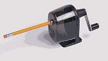
- Mechanical pencil sharpener
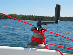
- Fishing reel and other reels for cables, wires, ropes, etc.
- Manually operated car window
- The carpenter's brace is a compound crank.
- The crank set that drives a handcycle through its handles.
- Hand winches
Foot-powered cranks
- The crankset that drives a bicycle via the pedals.
- Treadle sewing machine
Engines
Almost all reciprocating engines use cranks (with connecting rods) to transform the back-and-forth motion of the pistons into rotary motion. The cranks are incorporated into a crankshaft.
History
East Asia
Han China
The earliest hand-operated cranks appeared in China during the Han Dynasty (202 BC-220 AD), as Han era glazed-earthenware tomb models portray, and was used thereafter in China for silk-reeling and hemp-spinning, for the agricultural winnowing fan, in the water-powered flour-sifter, for hydraulic-powered metallurgic bellows, and in the well windlass.[3] In order to create a handle by means of a wheel to easily rotate their grain winnowers, the Chinese invented the crank handle and applied the centrifugal fan principle in the 2nd century BC.[4][5] The crank handle was used in well-windlasses, querns, mills, and many silk making machines.[6][7] The rotary winnowing fan greatly increased the efficiency of separating grain from husks and stalks. Harvesting grain by the use of rotary winnowing fan would not reach the Western World until the eighteenth century, where harvested grain was initially thrown up in the air by shovels or winnowing baskets.[8][9] However, the potential of the crank of converting circular motion into reciprocal one never seems to have been fully realized in China, and the crank was typically absent from such machines until the turn of the 20th century.[10]
Europe
Ancient Rome
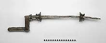
The handle of the rotary handmill which appeared in either 6th century BC Carthage or 5th century BC Celtiberian Spain and ultimately spread across the Roman Empire constitutes a crank.[12][13][1][2] A Roman iron crank of yet unknown purpose dating to the 2nd century AD was excavated in Augusta Raurica, Switzerland. The 82.5 cm long piece has fitted to one end a 15 cm long bronze handle, the other handle being lost.[11][14]
A ca. 40 cm long true iron crank was excavated, along with a pair of shattered mill-stones of 50−65 cm diameter and diverse iron items, in Aschheim, close to Munich. The crank-operated Roman mill is dated to the late 2nd century.[15] An often cited modern reconstruction of a bucket-chain pump driven by hand-cranked flywheels from the Nemi ships has been dismissed though as "archaeological fantasy".[16]
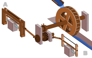
Evidence for the crank combined with a connecting rod appears in the Hierapolis sawmill in Asia Minor from the 3rd century and two stone sawmills at Gerasa, Roman Syria, and Ephesus, Asia Minor (both 6th century).[17] On the pediment of the Hierapolis mill, a waterwheel fed by a mill race is shown powering via a gear train two frame saws which cut rectangular blocks by the way of some kind of connecting rods and, through mechanical necessity, cranks. The accompanying inscription is in Greek.[18]
The crank and connecting rod mechanisms of the other two archaeologically attested sawmills worked without a gear train.[19][20] In ancient literature, there is a reference to the workings of water-powered marble saws close to Trier, now Germany, by the late 4th century poet Ausonius;[17] about the same time, these mill types seem also to be indicated by the Christian saint Gregory of Nyssa from Anatolia, demonstrating a diversified use of water-power in many parts of the Roman Empire[21] The three finds push back the date of the invention of the crank and connecting rod mechanism by a full millennium.[17] According to Tullia Ritti, Klaus Grewe, and Paul Kessener:
With the crank and connecting rod system, all elements for constructing a steam engine (invented in 1712) — Hero's aeolipile (generating steam power), the cylinder and piston (in metal force pumps), non-return valves (in water pumps), gearing (in water mills and clocks) — were known in Roman times.[22]
Medieval and Renaissance Europe
.jpeg)
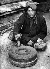
The crank became common in Europe by the early 15th century, seen in the works of those such as the military engineer Konrad Kyeser (1366–after 1405).[23] A rotary grindstone − the earliest representation thereof −[24] which is operated by a crank handle is shown in the Carolingian manuscript Utrecht Psalter; the pen drawing of around 830 goes back to a late antique original.[25] A musical tract ascribed to the abbot Odo of Cluny (ca. 878−942) describes a fretted stringed instrument which was sounded by a resined wheel turned with a crank; the device later appears in two 12th century illuminated manuscripts.[24] There are also two pictures of Fortuna cranking her wheel of destiny from this and the following century.[24] The first depictions of the compound crank in the carpenter's brace appear between 1420 and 1430 in various northern European artwork.[26] The rapid adoption of the compound crank can be traced in the works of the Anonymous of the Hussite Wars, an unknown German engineer writing on the state of the military technology of his day: first, the connecting-rod, applied to cranks, reappeared, second, double compound cranks also began to be equipped with connecting-rods and third, the flywheel was employed for these cranks to get them over the 'dead-spot'.[27]
The use of crank handles in trepanation drills was depicted in the 1887 edition of the Dictionnaire des Antiquités Grecques et Romaines to the credit of the Spanish Muslim surgeon Abu al-Qasim al-Zahrawi; however, the existence of such a device cannot be confirmed by the original illuminations and thus has to be discounted.[28] The Benedictine monk Theophilus Presbyter (c. 1070−1125) described crank handles "used in the turning of casting cores".[29] In Renaissance Italy, the earliest evidence of a compound crank and connecting-rod is found in the sketch books of Taccola, but the device is still mechanically misunderstood.[27] A sound grasp of the crank motion involved is demonstrated a little later by Pisanello, who painted a piston-pump driven by a water-wheel and operated by two simple cranks and two connecting-rods.[27] The Italian physician Guido da Vigevano (c. 1280−1349), planning for a new crusade, made illustrations for a paddle boat and war carriages that were propelled by manually turned compound cranks and gear wheels (center of image).[30] The Luttrell Psalter, dating to around 1340, describes a grindstone which was rotated by two cranks, one at each end of its axle; the geared hand-mill, operated either with one or two cranks, appeared later in the 15th century;[31]
Medieval cranes were occasionally powered by cranks, although more often by windlasses.[32]
The crank became common in Europe by the early 15th century, often seen in the works of those such as the German military engineer Konrad Kyeser.[31] Devices depicted in Kyeser's Bellifortis include cranked windlasses (instead of spoke-wheels) for spanning siege crossbows, cranked chain of buckets for water-lifting and cranks fitted to a wheel of bells.[31] Kyeser also equipped the Archimedes' screws for water-raising with a crank handle, an innovation which subsequently replaced the ancient practice of working the pipe by treading.[33] The earliest evidence for the fitting of a well-hoist with cranks is found in a miniature of c. 1425 in the German Hausbuch of the Mendel Foundation.[34]
.jpg)
The first depictions of the compound crank in the carpenter's brace appear between 1420 and 1430 in various northern European artwork.[26] The rapid adoption of the compound crank can be traced in the works of the Anonymous of the Hussite Wars, an unknown German engineer writing on the state of the military technology of his day: first, the connecting-rod, applied to cranks, reappeared, second, double compound cranks also began to be equipped with connecting-rods and third, the flywheel was employed for these cranks to get them over the 'dead-spot'.
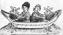
One of the drawings of the Anonymous of the Hussite Wars shows a boat with a pair of paddle-wheels at each end turned by men operating compound cranks (see above). The concept was much improved by the Italian engineer and writer Roberto Valturio in 1463, who devised a boat with five sets, where the parallel cranks are all joined to a single power source by one connecting-rod, an idea also taken up by his compatriot Italian painter Francesco di Giorgio.[35]
The 15th century also saw the introduction of cranked rack-and-pinion devices, called cranequins, which were fitted to the crossbow's stock as a means of exerting even more force while spanning the missile weapon (see right).[36] In the textile industry, cranked reels for winding skeins of yarn were introduced.[31]
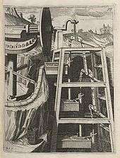
Around 1480, the early medieval rotary grindstone was improved with a treadle and crank mechanism. Cranks mounted on push-carts first appear in a German engraving of 1589.[37] Crankshafts were also described by Konrad Kyeser (d. 1405), Leonardo da Vinci (1452–1519)[38] and a Dutch farmer and windmill owner by the name Cornelis Corneliszoon van Uitgeest in 1592. His wind-powered sawmill used a crankshaft to convert a windmill's circular motion into a back-and-forward motion powering the saw. Corneliszoon was granted a patent for his crankshaft in 1597.
Modern Europe
From the 16th century onwards, evidence of cranks and connecting rods integrated into machine design becomes abundant in the technological treatises of the period: Agostino Ramelli's The Diverse and Artifactitious Machines of 1588 alone depicts eighteen examples, a number that rises in the Theatrum Machinarum Novum by Georg Andreas Böckler to 45 different machines, one third of the total.[39] Cranks were formerly common on some machines in the early 20th century; for example almost all phonographs before the 1930s were powered by clockwork motors wound with cranks. Reciprocating piston engines use cranks to convert the linear piston motion into rotational motion. Internal combustion engines of early 20th century automobiles were usually started with hand cranks (known as starting handles in the UK), before electric starters came into general use.
The 1918 Reo owner's manual describes how to hand crank the automobile:
- First: Make sure the gear shifting lever is in neutral position.
- Second: The clutch pedal is unlatched and the clutch engaged. The brake pedal is pushed forward as far as possible setting brakes on the rear wheel.
- Third: See that spark control lever, which is the short lever located on top of the steering wheel on the right side, is back as far as possible toward the driver and the long lever, on top of the steering column controlling the carburetor, is pushed forward about one inch from its retarded position.
- Fourth: Turn ignition switch to point marked "B" or "M"
- Fifth: Set the carburetor control on the steering column to the point marked "START." Be sure there is gasoline in the carburetor. Test for this by pressing down on the small pin projecting from the front of the bowl until the carburetor floods. If it fails to flood it shows that the fuel is not being delivered to the carburetor properly and the motor cannot be expected to start. See instructions on page 56 for filling the vacuum tank.
- Sixth: When it is certain the carburetor has a supply of fuel, grasp the handle of starting crank, push in endwise to engage ratchet with crank shaft pin and turn over the motor by giving a quick upward pull. Never push down, because if for any reason the motor should kick back, it would endanger the operator.
Middle East
Medieval Near East
The crank appears in the mid-9th centuryin several of the hydraulic devices described by the Banū Mūsā brothers in their Book of Ingenious Devices.[40] These devices, however, made only partial rotations and could not transmit much power,[41] although only a small modification would have been required to convert it to a crankshaft.[42]
Al-Jazari (1136–1206) described a crank and connecting rod system in a rotating machine in two of his water-raising machines.[38] His twin-cylinder pump incorporated a crankshaft,[43] including both the crank and shaft mechanisms.[44] In the Artuqid State (Turkey), Al-Jazari (1136–1206) described a crank and connecting rod system in a rotating machine, in two of his water-raising machines.[38] The twin-cylinder pump he invented incorporated a crankshaft,[45] including both the crank and shaft mechanisms.[46]
Crank axle
A crank axle is a crankshaft which also serves the purpose of an axle. It is used on steam locomotives with inside cylinders.
See also
References
- 1 2 Ritti, Grewe & Kessener 2007, p. 159
- 1 2 Lucas 2005, p. 5, fn. 9
- ↑ Needham, Joseph. (1986). Science and Civilization in China: Volume 4, Part 2, Mechanical Engineering. Taipei: Caves Books, Ltd. Pages 118–119.
- ↑ Quick, Graeme R. (2008). Remarkable Australian Farm Machines: Ingenuity on the Land. Grantham House Publishing. p. 68. ISBN 978-1869341053.
- ↑ Dorsey, Gray L. (1993). Jurisculture. Transaction Publishers. p. 82. ISBN 978-1560000907.
- ↑ Quick, Graeme R. (2008). Remarkable Australian Farm Machines: Ingenuity on the Land. Grantham House Publishing. p. 68. ISBN 978-1869341053.
- ↑ Dorsey, Gray L. (1993). Jurisculture. Transaction Publishers. p. 82. ISBN 978-1560000907.
- ↑ Bautista Paz, Emilio; Ceccarelli, Marco; Otero, Javier Echávarri; Sanz, José Luis Muñoz (2010). A Brief Illustrated History of Machines and Mechanisms. Springer (published May 12, 2010). p. 19. ISBN 978-9048125111.
- ↑ Du Bois, George (2014). Understanding China: Dangerous Resentments. Trafford on Demand. ISBN 978-1490745077.
- ↑ White, Jr. 1962, p. 104:
Yet a student of the Chinese technology of the early twentieth century remarks that even a generation ago the Chinese had not 'reached that stage where continuous rotary motion is substituted for reciprocating motion in technical contrivances such as the drill, lathe, saw, etc. To take this step familiarity with the crank is necessary. The crank in its simple rudimentary form we find in the [modern] Chinese windlass, which use of the device, however, has apparently not given the impulse to change reciprocating into circular motion in other contrivances'. In China the crank was known, but remained dormant for at least nineteen centuries, its explosive potential for applied mechanics being unrecognized and unexploited.
- 1 2 Schiöler 2009, pp. 113f.
- ↑ Curtis 2008, p. 375.
- ↑ Date: Frankel 2003, pp. 17–19
- ↑ Laur-Belart 1988, pp. 51–52, 56, fig. 42
- ↑ Volpert 1997, pp. 195, 199
- ↑ White, Jr. 1962, pp. 105f.; Oleson 1984, pp. 230f.
- 1 2 3 4 Ritti, Grewe & Kessener 2007, p. 161:
Because of the findings at Ephesus and Gerasa the invention of the crank and connecting rod system has had to be redated from the 13th to the 6th c; now the Hierapolis relief takes it back another three centuries, which confirms that water-powered stone saw mills were indeed in use when Ausonius wrote his Mosella.
- ↑ Ritti, Grewe & Kessener 2007, pp. 139–141
- ↑ Ritti, Grewe & Kessener 2007, pp. 149–153
- ↑ Mangartz 2006, pp. 579f.
- ↑ Wilson 2002, p. 16
- ↑ Ritti, Grewe & Kessener 2007, p. 156, fn. 74
- ↑ Needham 1986, p. 113.
- 1 2 3 White, Jr. 1962, p. 110
- ↑ Hägermann & Schneider 1997, pp. 425f.
- 1 2 White, Jr. 1962, p. 112
- 1 2 3 White, Jr. 1962, p. 113
- ↑ White, Jr. 1962, p. 170
- ↑ Needham 1986, pp. 112–113.
- ↑ Hall 1979, p. 80
- 1 2 3 4 White, Jr. 1962, p. 111
- ↑ Hall 1979, p. 48
- ↑ White, Jr. 1962, pp. 105, 111, 168
- ↑ White, Jr. 1962, p. 167; Hall 1979, p. 52
- ↑ White, Jr. 1962, p. 114
- ↑ Hall 1979, pp. 74f.
- ↑ White, Jr. 1962, p. 167
- 1 2 3 Ahmad Y Hassan. The Crank-Connecting Rod System in a Continuously Rotating Machine.
- ↑ White, Jr. 1962, p. 172
- ↑ A. F. L. Beeston, M. J. L. Young, J. D. Latham, Robert Bertram Serjeant (1990), The Cambridge History of Arabic Literature, Cambridge University Press, p. 266, ISBN 0-521-32763-6
- ↑ al-Hassan & Hill 1992, pp. 45, 61
- ↑ Banu Musa, Donald Routledge Hill (1979), The book of ingenious devices (Kitāb al-ḥiyal), Springer, pp. 23–4, ISBN 90-277-0833-9
- ↑ Sally Ganchy, Sarah Gancher (2009), Islam and Science, Medicine, and Technology, The Rosen Publishing Group, p. 41, ISBN 1-4358-5066-1
- ↑ Donald Hill (2012), The Book of Knowledge of Ingenious Mechanical Devices, page 273, Springer Science + Business Media
- ↑ Sally Ganchy, Sarah Gancher (2009), Islam and Science, Medicine, and Technology, The Rosen Publishing Group, p. 41, ISBN 1-4358-5066-1
- ↑ Donald Hill (2012), The Book of Knowledge of Ingenious Mechanical Devices, page 273, Springer Science + Business Media
Bibliography
- Curtis, Robert I. (2008). "Food Processing and Preparation". In Oleson, John Peter. The Oxford Handbook of Engineering and Technology in the Classical World. Oxford: Oxford University Press. ISBN 978-0-19-518731-1.
- Frankel, Rafael (2003), "The Olynthus Mill, Its Origin, and Diffusion: Typology and Distribution", American Journal of Archaeology, 107 (1): 1–21, doi:10.3764/aja.107.1.1
- Hall, Bert S. (1979), The Technological Illustrations of the So-Called "Anonymous of the Hussite Wars". Codex Latinus Monacensis 197, Part 1, Wiesbaden: Dr. Ludwig Reichert Verlag, ISBN 3-920153-93-6
- Hägermann, Dieter; Schneider, Helmuth (1997), Propyläen Technikgeschichte. Landbau und Handwerk, 750 v. Chr. bis 1000 n. Chr. (2nd ed.), Berlin, ISBN 3-549-05632-X
- al-Hassan, Ahmad Y.; Hill, Donald R. (1992), Islamic Technology. An Illustrated History, Cambridge University Press, ISBN 0-521-42239-6
- Lucas, Adam Robert (2005), "Industrial Milling in the Ancient and Medieval Worlds. A Survey of the Evidence for an Industrial Revolution in Medieval Europe", Technology and Culture, 46 (1): 1–30, doi:10.1353/tech.2005.0026
- Laur-Belart, Rudolf (1988), Führer durch Augusta Raurica (5th ed.), Augst
- Mangartz, Fritz (2006), "Zur Rekonstruktion der wassergetriebenen byzantinischen Steinsägemaschine von Ephesos, Türkei. Vorbericht", Archäologisches Korrespondenzblatt, 36 (1): 573–590
- Needham, Joseph (1991), Science and Civilisation in China: Volume 4, Physics and Physical Technology: Part 2, Mechanical Engineering, Cambridge University Press, ISBN 0-521-05803-1 .
- Oleson, John Peter (1984), Greek and Roman Mechanical Water-Lifting Devices: The History of a Technology, University of Toronto Press, ISBN 90-277-1693-5
- Volpert, Hans-Peter (1997), "Eine römische Kurbelmühle aus Aschheim, Lkr. München", Bericht der bayerischen Bodendenkmalpflege, 38: 193–199, ISBN 3-7749-2903-3
- White, Jr., Lynn (1962), Medieval Technology and Social Change, Oxford: At the Clarendon Press
- Ritti, Tullia; Grewe, Klaus; Kessener, Paul (2007), "A Relief of a Water-powered Stone Saw Mill on a Sarcophagus at Hierapolis and its Implications", Journal of Roman Archaeology, 20: 138–163
- Schiöler, Thorkild (2009), "Die Kurbelwelle von Augst und die römische Steinsägemühle", Helvetia Archaeologica, 40 (159/160), pp. 113–124
External links
- Crank highlight: Hypervideo of construction and operation of a four cylinder internal combustion engine courtesy of Ford Motor Company
- Kinematic Models for Design Digital Library (KMODDL) - Movies and photos of hundreds of working mechanical-systems models at Cornell University. Also includes an e-book library of classic texts on mechanical design and engineering.