S-Video
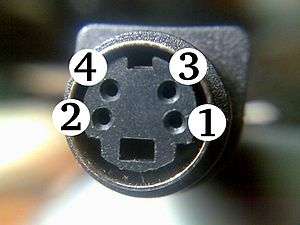 A standard 4-pin S-Video cable connector, with each signal pin paired with its own ground pin | |||
| Type | Analog video connector | ||
|---|---|---|---|
| Production history | |||
| Designed | 1987 | ||
| General specifications | |||
| Hot pluggable | Yes | ||
| External | Yes | ||
| Video signal | NTSC, PAL, or SECAM video | ||
| Pins | 4, 7, or 9 | ||
| Connector | Mini-DIN connector | ||
| Pin out | |||
 | |||
| Looking at the female connector | |||
| Pin 1 | GND | Ground (Y) | |
| Pin 2 | GND | Ground (C) | |
| Pin 3 | Y | Intensity (Luminance) | |
| Pin 4 | C | Color (Chrominance) | |
| The shells should be connected together by an overall screen/shield. However, the shield is often absent in low-end cables, which can result in picture degradation. | |||
S-Video (also known as separate video and Y/C)[1] is a signaling standard for standard definition video, typically 480i or 576i. By separating the black-and-white and coloring signals, it achieves better image quality than composite video, but has lower color resolution than component video.
Background
Standard analog television signals go through several processing steps on their way to being broadcast, each of which discards information and lowers the quality of the resulting images.
The image is originally captured in RGB form and then processed into three signals known as YPbPr. The first of these signals is called Y, which is created from all three original signals based on a formula that produces an overall brightness of the image, or luma. This signal closely matches a traditional black and white television signal and the Y/C method of encoding was key to offering backward compatibility. Once the Y signal is produced, it is subtracted from the blue signal to produce Pb and from the red signal to produce Pr. To recover the original RGB information for display, the signals are mixed with the Y to produce the original blue and red, and then the sum of those is mixed with the Y to recover the green.
A signal with three components is no easier to broadcast than the original three-signal RGB, so additional processing is required. The first step is to combine the Pb and Pr to form the C signal, for chrominance. The phase and amplitude of the signal represent the two original signals. This signal is then bandwidth-limited to comply with requirements for broadcasting. The resulting Y and C signals are mixed together to produce composite video. To play back composite video, the Y and C signals must be separated, and this is difficult to do without adding artifacts.
Each of these steps is subject to deliberate or unavoidable loss of quality. To retain that quality in the final image, it is desirable to eliminate as many of the encoding/decoding steps as possible. S-Video is an approach to this problem. It eliminates the final mixing of C with Y and subsequent separation at playback time.
Signal
The S-video cable carries video using two synchronized signal and ground pairs, termed Y and C.
Y is the luma signal, which carries the luminance – or black-and-white – of the picture, including synchronization pulses.
C is the chroma signal, which carries the chrominance – or coloring-in – of the picture. This signal contains both the saturation and the hue of the video.
The luminance signal carries horizontal and vertical sync pulses in the same way as a composite video signal. Luma is a signal carrying luminance after gamma correction, and is therefore termed "Y" because of the similarity to the lower-case Greek letter gamma.
In composite video, the signals co-exist on different frequencies. To achieve this, the luminance signal must be low-pass filtered, dulling the image. As S-Video maintains the two as separate signals, such detrimental low-pass filtering for luminance is unnecessary, although the chrominance signal still has limited bandwidth relative to component video.
Compared with component video, which carries the identical luminance signal but separates the color-difference signals into Cb/Pb and Cr/Pr, the color resolution of S-Video is limited by the modulation on a subcarrier frequency of 3.57 to 4.43 megahertz, depending on the standard. This difference is meaningless on home videotape systems, as the chrominance is already severely constrained by both VHS and Betamax.
Carrying the color information as one signal means that the color has to be encoded in some way, typically in accord with NTSC, PAL, or SECAM, depending on the applicable local standard.
Also, S-Video suffers from low color resolution. NTSC S-Video color resolution is typically 120 lines horizontal (approximately 160 pixels edge-to-edge), versus 250 lines horizontal for the Rec. 601-encoded signal of a DVD, or 30 lines horizontal for standard VCRs.
Use
In many European Union countries, S-Video was less common because of the dominance of SCART connectors, which are present on most existing televisions. It is possible for a player to output S-Video over SCART, but televisions' SCART connectors are not necessarily wired to accept it, and if not the display would show only a monochrome image.[2] In this case it is sometimes possible to modify the SCART adapter cable to make it work.
Game consoles sold in PAL territories usually do not output S-Video. Early consoles generally came with RF adapters, and the equally uncommon (on PAL televisions) composite video on the classic RCA type video jack. The Nintendo 64 was a special case: Both NTSC and PAL models could output S-Video.
In the US and some other NTSC countries, S-Video was provided on some video equipment, including most televisions and game consoles. The primary exceptions were VHS and Beta VCRs.
Physical connectors
Atari 800
The Atari 800 introduced separate Chroma/Luma output in late 1979. The signals were put on pin 1 and 5 of a 5-pin 180 degree DIN Connector socket. Atari did not sell a monitor for its 8-bit computer line, however.[3]
Commodore 64
The Commodore 64 released in 1982 also offers separate chroma and luma signals using a different connector. Although Commodore Business Machines did not use the term "S-Video" as the standard did not formally exist until 1987, a simple adapter connects the computer's "LCA" (luma-chroma-audio) 8-pin DIN socket to a S-Video display, or an S-Video device to the Commodore 1702 monitor's LCA jacks.[4]
4-pin mini-DIN
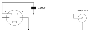
The four-pin mini-DIN connector is the most common of several S-Video connector types. The same mini-DIN connector is used in the Apple Desktop Bus for Macintosh computers and the two cable types can be interchanged.[5][6][7] Other connector variants include seven-pin locking "dub" connectors used on many professional S-VHS machines, and dual "Y" and "C" BNC connectors, often used for S-Video patch panels. Early Y/C video monitors often used phono (RCA connector) that were switchable between Y/C and composite video input. Though the connectors are different, the Y/C signals for all types are compatible.
The mini-DIN pins, being weak, sometimes bend. This can result in the loss of colour or other corruption (or loss) in the signal. A bent pin can be forced back into shape, but this carries the risk of the pin breaking off.
These plugs are usually made to be plug-compatible with S-video, and include optional features, such as component video using an adapter. They are not necessarily S-video, although they can be operated in that mode.
7-pin mini-DIN

Non-standard 7-pin mini-DIN connectors (termed "7P") are used in some computer equipment (PCs and Macs). A 7-pin socket accepts, and is pin compatible with, a standard 4-pin S-Video plug.[8] The three extra sockets may be used to supply composite (CVBS), an RGB or YPbPr video signal, or an I²C interface. The pinout usage varies among manufacturers.[8][9] In some implementations, the remaining pin must be grounded to enable the composite output or disable the S-Video output.
Some Dell laptops have a digital audio output in a 7-pin socket.[10]
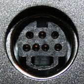
9-pin Video In/Video Out


9-pin connectors are used in graphics systems that feature the ability to input video as well as output it.[11][12] Again, there is no standardization between manufacturers as to which pin does what, and there are two known variants of the connector in use. As can be seen from the diagram above, although the S-Video signals are available on the corresponding pins, neither variant of the connector will accept an unmodified 4-pin S-Video plug, though they can be made to fit by removing the key from the plug. In the latter case, it becomes all too easy to misalign the plug when inserting it with consequent damage to the small pins.
See also
References
- ↑ S-Video – Definition About.com
- ↑ S-Video drama :(. camp0s.com
- ↑ Current, Michael. "Atari 8-bit FAQ". Retrieved 2018-02-23.
- ↑ Murray, David (2018-05-11). Commodore History Part 3 - The Commodore 64 (complete). The 8-Bit Guy. YouTube. Event occurs at 9:38. Retrieved 2018-05-12.
- ↑ "Macintosh: S-Video Port Confused with the ADB Port".
- ↑ "Compression for Great Digital Video: Power Tips, Techniques, and Common Sense".
- ↑ "A Practical Guide to Video and Audio Compression: From Sprockets and Rasters to Macro Blocks".
- 1 2 Keith Jack (2007). Video demystified: a handbook for the digital engineer. Newnes.
- ↑ ATI Radeon 7 pin SVID pinout.
- ↑ Dell (2009). "S-Video to TV-Composite Cable and SPDIF Adapter for Dell Inspiron".
- ↑ ATI Radeon: Using Video in and Video out.
- ↑ "ATI Radeon 9 pin VIVO pinout".
This article is based on material taken from the Free On-line Dictionary of Computing prior to 1 November 2008 and incorporated under the "relicensing" terms of the GFDL, version 1.3 or later.
| Wikimedia Commons has media related to S-Video connectors. |