Modular connector

A modular connector is an electrical connector that was originally designed for use in telephone wiring, but has since been used for many other purposes. Many applications that originally used a bulkier, more expensive connector have converted to modular connectors. Probably the best known applications of modular connectors are for telephone and Ethernet.
Modular connectors were originally used in the Registration Interface system, mandated by the Federal Communications Commission (FCC) in 1976 in which they became known as registered jacks. The registered jack specifications define the wiring patterns of the jacks, not the physical dimensions or geometry of the connectors of either gender. Instead, these latter aspects are covered by ISO standard 8877, first used in ISDN systems. TIA/EIA-568 is a standard for data circuits wired on modular connectors.
Other systems exist for assigning signals to modular connectors; physical interchangeability of plugs and jacks does not ensure interoperation, nor protection from electrical damage to circuits. For example, modular cables and connectors have been used to supply low-voltage AC or DC power and no clear standard exists for this application.
Nomenclature
Modular connectors also go by the names "modular phone jack/plug", "RJ connector" and "Western jack/plug". The term "modular connector" arose from its original use in a novel system of cabling designed to make telephone equipment more modular. This includes the 6P2C line and 4P4C handset connectors.
Registered jack designations describe the signals and wiring used for voice and data communication in modular and other connectors. It is very common to use a registered jack number to refer to the physical connector itself; for instance, the 8P8C modular connector type is often called RJ45 because the registered jack standard of that name was an early user of 8P8C modular connectors. A very popular use of 8P8C today is Ethernet over twisted pair, and that may be the best known context in which the name RJ45 is known. Likewise, the 4P4C connector is sometimes called RJ9 or RJ22 and various 6 position modular connectors are called RJ11.
History
The first types of small modular telephone connectors were created by AT&T in the mid-1960s for the plug-in handset and line cords of the Trimline telephone.[1] Driven by demand for multiple sets in residences with various lengths of cords, the Bell System introduced customer-connectable part kits and telephones, sold through PhoneCenter stores in the early 1970s.[2] For this purpose, Illinois Bell started installing modular telephone sets on a limited scale in June 1972. The patents by Edwin C. Hardesty and coworkers,US 3699498 (1972) and US 3860316 (1975), followed by other improvements, were the basis for the modular molded-plastic connectors that became commonplace for telephone cords by the 1980s. In 1976, these connectors were standardized nationally in the United States by the Registration Interface program of the Federal Communication Commission (FCC), which designated a series of Registered Jack (RJ) specifications for interconnection of customer-premises equipment to the public switched telephone network (PSTN).[3][4]
Gender
Modular connectors have gender: plugs are considered to be male, while jacks or sockets are considered to be female. Plugs are used to terminate cables and cords, while jacks are used for fixed locations on surfaces of walls, panels, and equipment. Other than telephone extension cables, cables with a modular plug on one end and a jack on the other are rare. Instead, cables are usually connected using a female-to-female adapter, having two jacks wired back-to-back.
Latching tab and orientation
Modular connectors are designed to latch together. As a plug is inserted into a jack, a plastic tab on the plug locks so that the plug cannot be pulled out. To remove the plug, the latching tab must be depressed against the plug to clear the locking edge. The standard orientation for installing a jack in a wall or panel is with the tab down.
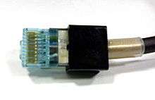
The latching tab may easily snag on other cables and break off resulting in loss of the secure latching feature. To prevent this, tabs are often protected with a boot over the plug, or a special tab design, on snagless cords. Most protective boots must be installed onto a cable before the modular plug is crimped on. This means that field retrofitting of these types of boots is not possible. However, protective boots or rigid protective ramp adapters are available which can be snapped over an installed unprotected modular plug.
Sizes and contacts
Modular connectors are designated using two numbers that represent the maximum number of contact positions and number of installed contacts, with each number followed by P and C, respectively. For example, 6P2C is a connector having six positions and two installed contacts. Alternate designations omit the letters while separating the position and contact quantities with either an x (6x2) or a slash (6/2).
When not installed, contacts are usually omitted from the outer positions inward, such that the number of contacts is almost always even. The connector body positions with omitted or unconnected contacts are unused for the electrical connection, but ensure that the plug fits correctly. For instance, RJ11 cables often have connectors with six positions and four contacts, to which are attached just two wires.
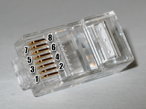
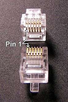
The contact positions are numbered sequentially starting from 1. When viewed head-on with the retention mechanism on the bottom, jacks will have contact position number 1 on the left and plugs will have it on the right. Contacts are numbered by the contact position. For example, on a six-position, two-contact plug, where the outermost four positions do not have contacts, the innermost two contacts are numbered 3 and 4.
Modular connectors are manufactured in four sizes, with 4-, 6-, 8-, and 10-positions. The insulating plastic bodies of 4P and 6P connectors have different widths, whereas 8P or 10P connectors share an even larger body width.

Internally, the contacts on the plugs have sharp prongs that, when crimped, pierce the wire insulation and connect with the conductor, a mechanism known as insulation displacement. Ethernet cables, in particular, may have solid or stranded (tinsel wire) conductors and the sharp prongs are different in the 8P8C connectors made for each type of wire. A modular plug for solid (single-strand) wire often has three slightly splayed prongs on each contact to securely surround and grip the conductor. Modular plugs for stranded have prongs that are designed to connect to multiple wire strands. Connector plugs are designed for either solid or stranded wire and a mismatch between plug and wire type may result in an unreliable connection.
Interchangeability
Some modular connectors are indexed: their dimensions are intentionally non-standard, preventing connections with connectors of standard dimensions. The means of indexing may be non-standard cross-sectional dimensions or shapes, retention mechanism dimensions or configuration. For example, a Modified Modular Jack using an offset latching tab was developed by Digital Equipment Corporation to prevent accidental interchange of data and telephone cables.
| Connector | Length | Width | Height |
|---|---|---|---|
| 4P4C | 7.7 | ||
| 6P4C | 12.34 | 9.65 | 6.60 |
| 8P8C | 21.46 | 11.68 | 8.30 |
The dimensions of modular connectors are such that a narrower plug can be inserted into a wider jack that has more positions than the plug, leaving the jack's outermost contacts unconnected. The contact spacing is always 1.02 mm (center to center). However, not all plugs from all manufacturers have this capability, and some jack manufacturers warn that their jacks are not designed to accept smaller plugs without damage. If an inserted plug lacks slots to accommodate the jack's contacts at the outermost extremes, it may permanently deform those outermost contacts of an incompatible jack. Excessive resistance may be encountered when inserting an incompatible plug, as the outermost contacts in the jack are forcibly deformed.
Special modular plugs have been manufactured (for example, the Siemon UP-2468[6]) which have extra slots beyond their standard contacts, to accommodate the wider jack's outermost contacts without damage. These special plug connectors can be visually identified by carefully looking for the extra slots molded into the plug. The molded plastic bodies of the special plugs may also be colored with a light blueish tinge, to aid in quick recognition. The special plugs are preferred for test equipment and adapters, which may be rapidly connected to a large number of corresponding connectors in quick succession for testing purposes. Use of the special plugs avoids inadvertent damage to the equipment under test, even when a narrower plug is inserted into a nominally incompatible wider jack.
Termination
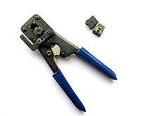
Termination of cables with modular connectors is similar across the various number of positions and contacts in the plug. To prevent damage to the plug and tool, the crimping tool must be matched to the plug being attached. For example, termination of a cable with an 8P8C plug involves using a crimping pliers containing an 8P8C die set.
A crimping die-set looks similar to an 8P8C jack, except for the eight teeth lining the top portion of the die. When the tool is operated, the die compresses around the 8P8C plug. As the die compresses, these teeth force the plug contacts down into the conductors of the cable being terminated. The crimper may also permanently deform part of the plastic plug body in such a way that it grips the outer sheath of the cable for secure fastening and strain relief. These actions permanently attaching the plug to the cable.
Pinout
The contact assignments (pinout) of modular connectors vary by application. Telephone network connections are standardized by registered jack designations, and Ethernet over twisted pair is specified by the TIA/EIA-568 standard. For other applications, standardization may be lacking; for example, multiple conventions exist for the use of 8P8C connectors in RS-232 applications.
For this reason, D-sub-to-modular adapters are typically shipped with the D-sub contacts (pins or sockets) terminated but not inserted into the connector body, so that the D-sub-to-modular contact pairing can be performed by the equipment maker.
4P4C
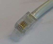
The 4P4C connector is the standard modular connector used on both ends of telephone handset cords, and is therefore often called a handset connector.[7]
This handset connector is not a registered jack, because it was not intended to connect directly to the telephone lines. However it is often referred to as RJ9, RJ10, or RJ22.
Handset wiring
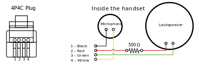
Handsets and often headsets for use with telephones commonly use a 4P4C connector. The two center pins are commonly used for the receiver, and the outer pins connect the transmitter, so that a reversal of pin connection is unaffected. Standard handset receivers function normally when their polarity is reversed, but the electret microphone transmitter used in most modern handsets may not. Many telephones include polarity protection, so that the polarity may be reversed without affecting operation. Handsets manufactured before 1985 using a carbon microphone transmitter are not sensitive to polarity. Some hands-free headsets also may have a 4P4C connector, but the wiring may differ from the above diagram.
Data port
The Macintosh 128K, Macintosh 512K and Macintosh Plus from Apple as well as the Amiga 1000 from Commodore used 4P4C connectors to connect the keyboard to the main computer housing. The connector provided power to the keyboard on the outer two contacts and received data signals on the inner pair. The cable between the computer and the keyboard was a coiled cord with an appearance very similar to a telephone handset cable.[8] The connector on the Amiga 1000 used crossover wiring, similar to a telephone handset. The connector wiring on the Apple computers, however, required a polarized straight through pinout. Using a telephone handset cable instead of the supplied cable could short out the +5 volt DC supply and damage the Apple computer or the keyboard.[9]
Some consumer equipment such as DirecTV set top boxes include a 4P4C low-speed data port connector.[10] Such connectors can be adapted for use with a computer's serial port so that control commands can be sent from the computer to the set top box.
6P6C
Modular plugs are described as containing a number of potential contact "positions" and the actual number of contacts installed within these positions. RJ11, RJ14, and RJ25 all use the same six-position modular connector, thus are physically identical except for the different number of contacts (two, four and six respectively).
The 6P2C, 6P4C, and 6P6C modular connectors are probably best known for their use as RJ11, RJ14, and RJ25 registered jacks respectively.
RJ11 is a physical interface often used for terminating telephone wires. It is probably the most familiar of the registered jacks, being used for single line POTS telephone jacks in most homes across the world.
RJ14 is similar, but for two lines, and RJ25 is for three lines. RJ61 is a similar registered jack for four lines. The telephone line cord and its plug are more often a true RJ11 with only two contacts.
RJ11 wiring
Cables sold as RJ11 often actually use 6P4C RJ14 connectors (six position, four contacts), with four wires running to a central junction box. Two of its six possible contact positions connect tip and ring, and the other two contact positions are then unused. 6P2C and 6P6C can also be found in stores.
The contacts other than the two central tip and ring contacts are in practice used for various things such as a ground for selective ringers, low voltage power for a dial light, or for 'anti-tinkle' circuitry to prevent pulse dialing phones from ringing the bell on other extensions. With tone dialing, anti-tinkle measures are not required.
Pinout
The pins of the 6P6C connector are numbered 1 to 6, counting left to right when holding the connector tab side down with the opening for the cable facing the viewer.
| Position | Pair | T/R | ± | RJ11 | RJ14 | RJ25 | Twisted pair colors | 25-pair colors | Old colors[a] | German colors[b] | Australian colors |
|---|---|---|---|---|---|---|---|---|---|---|---|
| 1 | 3 | T | + | T3 | white/green |
white/green |
white |
pink |
orange | ||
| 2 | 2 | T | + | T2 | T2 | white/orange |
white/orange |
black |
green |
red | |
| 3 | 1 | R | − | R1 | R1 | R1 | blue |
blue/white |
red |
white |
blue |
| 4 | 1 | T | + | T1 | T1 | T1 | white/blue |
white/blue |
green |
brown |
white |
| 5 | 2 | R | − | R2 | R2 | orange |
orange/white |
yellow |
yellow |
black | |
| 6 | 3 | R | − | R3 | green |
green/white |
blue |
gray |
green |
- ^[a] While the old solid color code was well established for pair 1 and usually pair 2, there are several conflicting conventions for pair 3 (and sometimes even pair 2). The colors shown above were taken from a vendor of "silver satin" flat 8-conductor phone cable that claims to be standard. 6-pair solid (old) bellwire cables previously used by the Bell System use white for pair 3 tip but some vendors' cable may substitute orange for white. At least one other vendor of flat 8-conductor cable uses the sequence blue, orange, black, red, green, yellow, brown and white/slate.
- ^[b] This color scheme originates in the (withdrawn) national standard DIN 47100. The scheme shown here is the correct color code for interfacing with the RJ connector standards.
However, with German domestic telephone equipment (and that in some neighbouring countries), 6P4C plugs and sockets are typically only used to connect the telephone cable to the phone base unit, whereas the mechanically different TAE plug is used at the other end of the cable. Older base units may accommodate the additional connectors of TAE (E, W, a2, b2) and may feature non-RJ standard sockets that can be connected "straight" to TAE plugs. Further, flat DIN 47100 cables typically place the wires in ascending order. When used directly with 6P4C plugs, the colors will be scrambled.
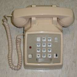
Powered version of RJ11
In the powered version, Pins 2 and 5 (black and yellow) may carry low voltage AC or DC power. While the phone line itself (tip and ring) supplies enough power for most telephone terminals, old telephone terminals with incandescent lights in them (such as the classic Western Electric Princess and Trimline telephones) need more power than the phone line can supply. Typically, the power on Pins 2 and 5 comes from a transformer plugged into a wall near one jack, supplying power to all of the jacks in the house. Trimline and Princess phone dial lights are rated at 6.3 volts and the transformer output is typically around 5 volts, providing a long service life for the incandescent lamps.
Compatibility with structured cabling
With the rise of Ethernet local area networks operating over Cat5e and Cat6 unshielded twisted pair cable, structured cabling networks adhering to TIA/EIA-568-B, ISO/IEC 11801 or ISO/IEC 15018 (home networks) are widely used for both computer networking and analog telephony, but these standards specify the T568-A or T568-B pin-outs compatible with Ethernet. The 8P8C ("RJ45") jack used by structured cabling physically accepts the 6-position connector used by RJ11, RJ14 and RJ25, but only RJ11 and RJ14 have full electrical compatibility. Ethernet compatible pin-outs "split" the third pair of RJ25 across two separate cable pairs, rendering that pair unusable by an analog phone. This was necessary to preserve the electrical properties of those pairs for Ethernet, which operates at much higher frequencies than analog telephony.
Both the third and fourth pairs of RJ61 are similarly split. Because of this incompatibility, and because they were never very common to begin with, the TIA/EIA-568-B conventions are displacing RJ25 and RJ61 for telephones with more than two lines.
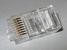
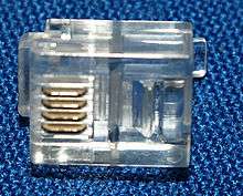
8P8C (8 position 8 contact)
The 8 position 8 contact (8P8C) connector is a modular connector commonly used to terminate twisted pair and multi-conductor flat cable. These connectors are commonly used for Ethernet over twisted pair, registered jacks and other telephone applications, RS-232 serial using the EIA/TIA-561 and Yost standards, and other applications involving unshielded twisted pair, shielded twisted pair, and multi-conductor flat cable.
An 8P8C modular connection has two paired components: the male plug and the female jack, each with eight equally-spaced conductors. On the plug, these conductors are flat contacts positioned parallel with the connector body. Inside the jack, the contacts are suspended diagonally toward the insertion interface. When an 8P8C plug is mated with an 8P8C jack, the contacts meet and create an electrical connection. Spring tension in the jack's contacts ensures a good interface with the plug and allows for slight travel during insertion and removal.
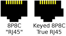
Although commonly referred to as an RJ45 in the context of Ethernet and category 5 cables, it is incorrect to refer to a generic 8P8C connector as an RJ45.[11][12][13] A telephone-system-standard RJ45 plug has a key which excludes insertion in an un-keyed 8P8C socket.[14] The registered jack (RJ) standard specifies a different mechanical interface and wiring scheme for an RJ45S from TIA/EIA-568-B which is often used for modular connectors used in Ethernet and telephone applications. 8P8C modular plugs and jacks look very similar to the plugs and jacks used for FCC's registered jack RJ45 variants, although the RJ45S is not compatible with 8P8C modular connectors.
The original RJ45S jack mates with a keyed 8P2C modular plug,[15][16] and has pins 4 and 5 (the middle positions) wired for ring and tip of a single telephone line and pins 7 and 8 shorting a programming resistor. It was intended for high speed modems, and is obsolete.
Telephone installers who wired RJ45S modem jacks or RJ61X telephone jacks were familiar with the pin assignments that were part of the standard. However, the standard un-keyed modular connectors became ubiquitous for computer networking, and informally inherited the name RJ45. RJ45S uses a keyed variety of the 8P body, meaning it has an extra tab that a common modular connector cannot mate with.
Because telephone RJ61 and data RJ45/RJ48 connectors were not widely used and 8P8C connectors in computers became ubiquitous, RJ45 is used to refer to 8P8C un-keyed modular connectors. This practice is followed by electronics catalogs and many electronic equipment manuals. In common usage, RJ45 may also refer to the pin assignments for the attached cable, which are actually defined as T568A and T568B in wiring standards such as TIA/EIA-568.
Standardization
The shape and dimensions of an 8P8C modular connector are specified for U.S. telephone applications by the Administrative Council for Terminal Attachment (ACTA) in national standard ANSI/TIA-1096-A. This standard does not use the short term 8P8C and covers more than just 8P8C modular connectors, but the 8P8C modular connector type is the eight position connector type described therein, with eight contacts installed. The international standard is ISO-8877.
For data communication applications (LAN, structured cabling), International Standard IEC 60603 specifies in parts 7-1, 7-2, 7-4, 7-5, and 7-7 not only the same physical dimensions, but also high-frequency performance requirements for shielded and unshielded versions of this connector for frequencies up to 100, 250 and 600 MHz, respectively.
Pinout
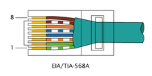
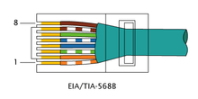
Connectors are frequently terminated using the T568A or T568B assignments that are defined in TIA/EIA-568. The drawings to the right show that the copper connections and pairing are the same, the only difference is that the orange and green pairs (colors) are swapped. A cable wired as T568A at one end and T568B at the other (Tx and Rx pairs reversed) is a "crossover" cable. Before the widespread acceptance of auto MDI-X capabilities a crossover cable was needed to interconnect similar network equipment (such as Ethernet hubs to Ethernet hubs). A cable wired the same at both ends is called a "patch" or "straight-through" cable, because no pin/pair assignments are swapped. Crossover cables are sometimes still used to connect two computers together without a switch or hub, however most network interface cards (NIC) in use today implement auto MDI-X to automatically configure themselves based on the type of cable plugged into them. If a "patch" or "straight" cable is used to connect two computers with auto MDI-X capable NICs, one NIC will configure itself to swap the functions of its Tx and Rx wire pairs.
| Pin | T568A pair | T568A color | T568B pair | T568B color | 10BASE-T/100BASE-TX signal id.[17] | 1G/10GBASE-T signal id. | Wire | Diagram |
|---|---|---|---|---|---|---|---|---|
| 1 | 3 | white/green stripe | 2 | white/orange stripe | TD+ | DA+ | tip | Pin numbering on plug. Connected pins on plug and jack have the same number. |
| 2 | 3 | green solid | 2 | orange solid | TD− | DA− | ring | |
| 3 | 2 | white/orange stripe | 3 | white/green stripe | RD+ | DB+ | tip | |
| 4 | 1 | blue solid | 1 | blue solid | NC | DC+ | ring | |
| 5 | 1 | white/blue stripe | 1 | white/blue stripe | NC | DC− | tip | |
| 6 | 2 | orange solid | 3 | green solid | RD− | DB− | ring | |
| 7 | 4 | white/brown stripe | 4 | white/brown stripe | NC | DD+ | tip | |
| 8 | 4 | brown solid | 4 | brown solid | NC | DD− | ring |
Types and incompatibility
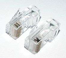
Two types of 8P8C plugs and installation tools (used for crimping the plug onto a cable) are commonly available: Western Electric/Stewart Stamping (WE/SS) and Tyco/AMP. While both types look remarkably similar, the tooling used to install the two different plug types is mutually exclusive and cannot be interchanged between the two types. WE/SS compatible plugs are available from a large number of manufacturers, whereas Tyco/AMP plugs are produced exclusively by Tyco Electronics. Both types of modular plugs will plug into the same standard 8P8C modular jack.
WE/SS and Tyco/AMP 8P8C plugs have different spacing for the cable strain relief.[18][19] Thus, using a WE/SS 8P8C crimp die set on a Tyco/AMP 8P8C plug will crush the top of the connector and damage the crimp die set, and vice versa. While the WE/SS compatible plug is produced by a larger number of manufacturers than the Tyco/AMP plug, it is still important to know what style is being used to avoid damaging the plug or tool during crimping.
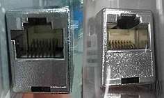
Both types of 8P8C plugs are available in shielded and unshielded varieties, depending on the attenuation tolerance needed. Shielded plugs are more expensive and require shielded cable, but have a lower attenuation and can reduce signal noise.
Although a narrower 4-pin and 6-pin connector will fit into the wider 8-pin jack, the smaller connector can potentially damage the contacts of the larger, because the outside edges of the smaller connector press onto the contacts of the larger. The outside edges of an RJ11/RJ45 plug typically project out by about 0.5 to 1.0 mm further than the contact surfaces, and these edges press the outermost contacts of the larger connector further than if a full-size connector were plugged in. The smaller connector may therefore permanently bend pins 1, 8 or 2, 7 of the larger connector.
Applications
8P8C are commonly used in computer networking and telephone applications, where the plug on each end is an 8P8C modular plug wired according to a TIA/EIA standard. Most wired Ethernet network communications today are carried over Category 5e or Category 6 cable with an 8P8C modular plug crimped on each end.
The 8P8C modular connector is also used for RS-232 serial interfaces according to the EIA/TIA-561 standard.[20] This application is common as a console interface on network equipment such as switches and routers. Other applications include other networking services such as ISDN and T1.
In floodwired[lower-alpha 1] environments the center (blue) pair is often used to carry telephony signals. Where so wired, the physical layout of the 8P8C modular jack allows for the insertion of an RJ11 plug in the center of the jack, provided the RJ11 plug is wired in true compliance with the U.S. telephony standards (RJ11) using the center pair. The formal approach to connect telephony equipment is the insertion of a type-approved converter.
The remaining (brown) pair is increasingly used for Power over Ethernet (PoE). Legacy equipment may use just this pair; this conflicts with other equipment, because some manufacturers previously short circuited unused pairs to reduce signal crosstalk. Some routers, bridges and switches can be powered by the unused 4 lines—blues (+) and browns (−)—to carry current to the unit. There is now a standardized wiring scheme for Power over Ethernet.
Different manufacturers of 8P8C modular jacks arrange for the pins of the 8P8C modular connector jack to be linked to wire connectors (often IDC type terminals) that are in a different physical arrangement from that of other manufacturers: Thus, for example, if a technician is in the habit of connecting the white/orange wire to the "bottom right hand" IDC terminal, which links it to 8P8C modular connector pin 1, in jacks made by other manufacturers this terminal may instead connect to 8P8C modular connector pin 2 (or any other pin). Labels and manufacturer's documentation should be consulted whenever an unfamiliar connector is first encountered.
8P8C modular connectors are also commonly used as a microphone connector for PMR, LMR, and amateur radio transceivers. Frequently the pinout is different, usually mirrored (i.e. what would be pins 1 to 8 in the TIA/EIA-568 standard might be pins 8 to 1 in the radio and its manual).
In landline telephony, an 8P8C jack is used at the point a line enters the building to allow the line to be broken to insert automatic dialling equipment, including intrusion alarm panels. In analogue mobile telephony, the 8P8C connector was used to connect an AMPS cellular handset to its (separate) base unit; this usage is now obsolete.
Commonly (and incorrectly) referred to as "RJ45", the physical connector is standardized as the IEC 60603-7 8P8C modular connector with different "categories" of performance. The physical dimensions of the male and female connectors are specified in ANSI/TIA-1096-A and ISO-8877 standards and normally wired to the T568A and T568B pinouts specified in the TIA/EIA-568 standard to be compatible with both telephone and Ethernet.
A similar standard jack once used for modem/data connections, the RJ45S, used a "keyed" variety of the 8P8C body with an extra tab that prevents it mating with other connectors; the visual difference compared to the more common 8P8C is subtle, but it is a different connector. The original RJ45S[15][21] keyed 8P2C modular connector had pins 5 and 4 wired for tip and ring of a single telephone line and pins 7 and 8 shorting a programming resistor, but is obsolete today.
Electronics catalogs commonly advertise 8P8C modular connectors as "RJ45". An installer can wire the jack to any pin-out or use it as part of a generic structured cabling system such as ISO/IEC 15018 or ISO/IEC 11801 using RJ45 patch panels for both phone and data. Virtually all electronic equipment which uses an 8P8C connector (or possibly any 8P connector at all) will document it as an "RJ45" connector.
Crossover cables
A router to router crossover cable uses two 8 position connectors and a UTP (Unshielded Twisted Pair) cable with differently wired connectors at each end. Although a registered jack specifies the wiring pattern and corresponding form factor rather than just the pin assignments or the physical connector, crossover cables are often incorrectly marketed as "RJ45 crossover cables".
10P10C
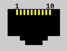
The 10P10C connector is commonly referred to as an RJ50 connector, although this was never a standard registered jack in the Universal Service Order Codes. The 10P10C has 10 contact positions and 10 contacts.
The most common uses of the 10P10C connector are in proprietary data transfer systems,[22] such as the Digiboard[23] and Equinox Super-Serial multi-port TIA-232 adapters.[23] 10P10C connectors are also used to implement RS-485 interfaces, and for data link connections in APC and Eaton uninterruptible power supplies. In the latter case, a keyed 10P10C plug with a protrusion on the pin 1 side near the back is used.
This connector is also used by some vendors, such as BOCA, for expansion modules of their multi-port RS-232C serial boards. For example, Cyclades (later absorbed by Equinox) used pin 1 as an "RI" (ring indicator) signal, which is seldom used, allowing an 8P8C plug to be inserted to their 10P10C socket for most applications. The Cisco Systems STS-10X terminal server features this connector. FordNet, a five-pair communications networking medium, also used the 10P10C between terminals.
Motorola uses the 10-pin connector as a microphone connector in several of their mobile radio product lines.
Polycom utilizes this connector to interconnect multiple SoundStructure audio mixers.
The 10-pin connector is also used by Demag Cranes AG[24] in some pendant connections. National Instruments is also using the 10p10c connector for their NI 9237.[25]
MTS Systems Corporation is using the 10p10c connector for their MTS FlexTest® Controller Family.
See also
Notes
- ↑ Floodwire is a chiefly British term for installing communications cables in a massive fashion in anticipation of their eventual use.
References
- ↑ Krumreich C.L., Mosing L.W., The Evolution of a Telephone, Bell Laboratories Record 44(1) p.14 (January 1966)
- ↑ Walden S.W., Telephone Sets Go Mod (Modular, That Is), Bell Laboratories Record, Vol. 52(8) p. 238 (Sept. 1974)
- ↑ AT&T, Registration Interface—Selection and General Information, Bell System Practices, Section 463-400-100 Issue 1, May 1976
- ↑ FCC 47 CFR Part 68 Connection of Terminal Equipment to the Telephone Network, Section 68.502 superseded by T1.TR5-1999
- ↑ "Modular Connectors" (PDF). Cambridge connectors. Retrieved 2012-09-28.
- ↑ "Universal Modular Plug".
- ↑ BICSI (October 7, 2002). "Background Information". Telecommunications Cabling Installation (2nd ed.). McGraw-Hill Professional. p. 88. ISBN 0-07-140979-3.
4-position and 4-contact connectors are used primarily for telephone handset cords.
- ↑ "Apple Macintosh Plus", My Old Computers .
- ↑ "Mac Plus Keyboard Cable", Syrinx, UK: Megadon,
...the cable is the same as the telephone cable that connects handsets to the phone, unfortunately [...] this type of cable and pretty much any type of pre manufactured cable [...] is wired wrong for the Mac Plus. Under no circumstances should you use this cable as you will damage your keyboard and/or your Mac!
- ↑ "Direc TV Channel Control" (wiki). GB-PVR. Archived from the original on 2008-10-19.
Each end of a handset cord is wired opposite the other...
- ↑ Trulove 2005, pp. 23, 132: ‘Designing LAN Wiring Systems: The 8-pin modular jack is sometimes referred to as an "RJ-45", because the connector/jack components are the same. However, RJ-45 actually applies to a special purpose jack configuration that is not used in LAN or standard telephone wiring. […] Work Area Outlets: Modular jacks are often referred to as "RJ-45" jacks. This is not really the correct moniker, although it is in very common use.’
- ↑ Oliviero, Andrew; Woodward, Bill (July 20, 2009). "Connectors". Cabling: The Complete Guide to Copper and Fiber-Optic Networking (4th ed.). Sybex. p. 294. ISBN 0-470-47707-5.
The RJ (registered jack) prefix is one of the most widely (and incorrectly) used prefixes in the computer industry; nearly everyone, including people working for cabling companies, is guilty of referring to an eight-position modular jack (sometimes called an 8P8C) as an RJ-45.
- ↑ Semenov, Andrey B.; Strizhakov, Stanislav K.; Suncheley, Igor R. (October 3, 2002). "Electrical Cable Connectors". Structured cable systems. Springer. p. 129. ISBN 3-540-43000-8.
The traditional 8-contact connector, which is called Western Plug, 8PMJ (8-position modular jack), 8P8C (8 position 8 conductor), or somewhat incorrectly RJ-45, is used widely in SCS practice.
- ↑ Trulove 2005, p. 219: ‘User Cords and Connectors: This 8-pin modular plug is probably the most subject to name abuse, because it resembles the specialized RJ-45 connector. However, the RJ-45 wiring pattern (which includes an interface programming resistor) is so radically different from that of T568A and B that it really should not be called by that name at all.’
- 1 2 Modular jack wiring, Ontario, California: HVS, archived from the original on 2010-02-08
- ↑ Modular wiring reference, Siemon
- ↑ IEEE 802.3 14.5.1 MDI connectors
- ↑ "Stewart Connector 937-SP-3088 – Eight conductor/eight position line cord module" (PDF). Glen Rock, Pennsylvania: Bel Stewart Connector. 2006-02-01. Retrieved 2018-04-18.
- ↑ "Tyco/AMP 5-554739-2 – Modular plug assembly, 8 position, flat oval cable" (PDF). Harrisburg, Pennsylvania: Tyco Electronics. 2008-03-31. Retrieved 2009-09-10.
- ↑ "RJ45", Layer 1, Zytrax .
- ↑ "Modular Wiring Reference". Siemon. Retrieved 2010-10-14.
- ↑ 10 pin RJ50 (10P10C) male (connector diagram and applications), Pinouts guide
- 1 2 Digi PortServer TS 10P10C (RJ50) Modular RS-232 pinout, Pinouts guide .
- ↑ Demag cranes AG .
- ↑ NI 9237 4-Channel, ±25 mV/V, 24-Bit Simultaneous Bridge Module specifications .
Bibliography
- Trulove, James (December 19, 2005), LAN wiring (3rd ed.), McGraw-Hill Professional, ISBN 0-07-145975-8 .
Standards
- ANSI/TIA-968-A: Telephone terminal equipment: Technical requirements for connection of terminal equipment to the telephone network
- ANSI/TIA-1096-A: Telecommunications telephone terminal equipment connector requirements for connection of terminal equipment to the telephone network
- IEC 60603-7-1: Connectors for electronic equipment: Part 7-1: Detail specification for 8-way, shielded free and fixed connectors with common mating features, with assessed quality
- IEC 60603-7-2: Connectors for electronic equipment: Part 7-2: Detail specification for 8-way, unshielded, free and fixed connectors, for data transmissions with frequencies up to 100 MHz
- IEC 60603-7-4: Connectors for electronic equipment: Part 7-4: Detail specification for 8-way, unshielded, free and fixed connectors, for data transmissions with frequencies up to 250 MHz
- IEC 60603-7-5: Connectors for electronic equipment: Part 7-5: Detail specification for 8-way, shielded, free and fixed connectors, for data transmissions with frequencies up to 250 MHz
- IEC 60603-7-7: Connectors for electronic equipment: Part 7-7: Detail specification for 8-way, shielded, free and fixed connectors, for data transmissions with frequencies up to 600 MHz
- ISO/IEC 8877, EN 28877: Information Technology—Telecommunications and Information Exchange between Systems—Interface Connector and Contact Assignments for ISDN Basic Access Interface Located at Reference Points S and T
- Registered Jack references are US government documents that define modular connectors for telecommunications. (Note: 4P4C and 10P10C connectors are NOT defined in these standards.)
External links
| Wikimedia Commons has media related to Modular connectors. |
- How to Make a Network Cable, a how-to article from wikiHow
- John R. Carlsen: On wiring modular telephone connectors
- Modular wiring reference showing differences between 8P8C, true RJ45 8-position keyed connector, 6P6C, and 6-position modified offset tab
- Common outlet configurations graphical representation of twisted pair pinouts
- Catalog page showing the difference between solid and stranded contacts
- List of pinouts for many applications of 8P8C connectors