Pinout

In electronics, a pinout (sometimes written "pin-out") is a cross-reference between the contacts, or pins, of an electrical connector or electronic component, and their functions. "Pinout" now supersedes the term "basing diagram" that was the standard terminology used by the manufacturers of vacuum tubes and the RMA. The RMA started its standardization in 1934, collecting and correlating tube data for registration at what was to become the EIA. The EIA (Electronic Industries Alliance) now has many sectors reporting to it, and sets what are known as EIA standards where all registered pinouts and registered jacks can be found.
Purpose
The functions of contacts in electrical connectors, be they power- or signaling-related, must be specified in order for connectors to be interchangeable. When connected, each contact of a connector must mate with the contact on the other connector that has the same function. If contacts of disparate functions are allowed to make contact, the connection may fail and damage may result. Therefore, pinouts are a vital reference when building and testing connectors, cables, and adapters.
Terminology
While one usage of the word pin is to refer to electrical contacts of, specifically, the male gender, its usage in pinout does not imply gender: the contact-to-function cross-reference for a connector that has only female socket contacts is still called a pinout.
Representation
The pinout can typically be shown as a table or diagram, though it is necessary to clarify how to view the diagram, stating if it shows the backside of the connector (where wires are attached) or the "mating face" of the connector. Published pinouts, which are particularly important when different manufacturers want to interconnect their products using open standards, are typically provided by the connector or equipment manufacturer. Some pinouts are provided by 3rd parties since some connectors are not well documented by the manufacturer.
While repairing electronic devices, an electronics technician uses electronic test equipment to "pin out" each component on a PCB. The technician probes each pin of the component in turn, comparing the expected signal on each pin to the actual signal on that pin.
Example pinouts
USB pinout
Viewed from the front (outside) of Female Type A USB receptacle:

- +5V (Red)
- −Data (White)
- +Data (Green)
- GND (Black)
PS/2 pinout
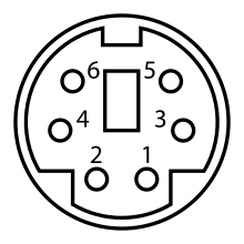
| Pin number | Name | Purpose |
|---|---|---|
| 1 | DATA | Data |
| 2 | Not used | |
| 3 | GND | Ground |
| 4 | Vcc | +5V Common-collector voltage |
| 5 | CLK | Clock signal |
| 6 | Not used |
4017 decade counter

| Pin number | Name | Purpose |
|---|---|---|
| 1 | 6 | The 6th sequential output |
| 2 | 2 | The 2nd sequential output |
| 3 | 1 | The 1st sequential output |
| 4 | 3 | The 3rd sequential output |
| 5 | 7 | The 7th sequential output |
| 6 | 8 | The 8th sequential output |
| 7 | 4 | The 4th sequential output |
| 8 | 0 V, VDD | The connection to the 0 V rail |
| 9 | 9 | The 9th sequential output |
| 10 | 5 | The 5th sequential output |
| 11 | 10 | The 10th sequential output |
| 12 | CO | Carry out output - outputs high on counts 0 to 4, outputs low on counts 5 to 9 (thus a transition from low to high occurs when counting from 9 back to 0) |
| 13 | EN | Latch enable - latches on the current output when high (i.e. the chip counts when EN is low) |
| 14 | CLK | Clock in |
| 15 | RST | Reset - sets output 1 high and outputs 2 through 10 low, when taken high |
| 16 | +9 V, VCC | The connection to the +VCC rail (voltage between +3 V and +15 V) |
LM741 operational amplifier

See also
External links
| Wikimedia Commons has media related to Electronic diagrams. |
- The Hardware Book - Pinout collection
- Crossover search of pinouts at pinout.net
- Pinouts of hardware connectors with description of common interfaces at pinouts.ru
- Pinouts (pin-out) - Historical Pinouts collection
- 74xxx and 40xx (pin-outs) - Pinouts collection
- Pin Configuration of ICs and semiconductors (pin-outs) - Pinouts collection