RF power amplifier
.jpg)
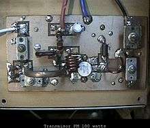
A radio frequency power amplifier (RF power amplifier) is a type of electronic amplifier that converts a low-power radio-frequency signal into a higher power signal. Typically, RF power amplifiers drive the antenna of a transmitter. Design goals often include gain, power output, bandwidth, power efficiency, linearity (low signal compression at rated output), input and output impedance matching, and heat dissipation.
Amplifier classes
Many modern RF amplifiers operate in different modes, called “classes”, to help achieve different design goals. Some classes are class A, class B, class C and class E.[1] There is a Class D, but those amplifiers can work only with low frequency signals typically used in audio equipment.
Solid state vs. vacuum tube amplifiers
Modern RF power amplifiers use solid-state devices such as bipolar junction transistors and MOSFETs.[2] Transistors and other modern solid-state devices have replaced vacuum tubes in most electronic devices, but tubes are still used in some high-power transmitters (see Valve RF amplifier). Although mechanically robust, transistors are electrically fragile – they are easilly damaged by excess voltage or current. Tubes are mechanically fragile, but electrically robust – they can handle remarkably high electrical overloads without appreciable damage.
Applications
The basic applications of the RF power amplifier include driving to another high power source, driving a transmitting antenna and exciting microwave cavity resonators. Among these applications, driving transmitter antennas is most well known. The transmitter–receivers are used not only for voice and data communication but also for weather sensing (in the form of a radar).
Wideband amplifier design
Impedance transformations over large bandwidth are difficult to realize, thus most wideband amplifiers use 50 Ω output loading. Transistor output power is then limited to

is defined as the breakdown voltage

is defined as the knee voltage

and typically

The loadline method is often used in RF power amplifier design.[3]
References
- ↑ Cloutier, Stephen R. "Class E AM Transmitter Descriptions, Circuits, Etc". www.classeradio.com. WA1QIX. Retrieved 6 June 2015.
- ↑ MFJ Enterprises. "Ameritron ALS-1300 1200-watt NO TUNE TMOS-FET AMPLIFIER". MFJ Enterprises. Retrieved 6 June 2015.
- ↑ Matthew Ozalas (January 14, 2015). "How to Design an RF Power Amplifier: The Basics". youtube.com. Retrieved 2015-02-10.
External links
| Wikimedia Commons has media related to RF power amplifiers. |
- Carlos Fuentes (October 2008). "Microwave Power Amplifier Fundamentals" (PDF). Retrieved 2013-03-05.
- Khanifar, Ahmad. "RF Power Amplifier Design for Digital Predistortion". www.linamptech.com. Retrieved 1 December 2014.