Class-D amplifier
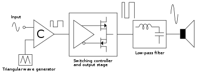
Note: For clarity, signal periods are not shown to scale.
A class-D amplifier or switching amplifier is an electronic amplifier in which the amplifying devices (transistors, usually MOSFETs) operate as electronic switches, and not as linear gain devices as in other amplifiers. They are rapidly switching back and forth between the supply rails, being fed by a modulator using pulse width, pulse density, or related techniques to encode the audio input into a pulse train. The audio escapes through a simple low-pass filter into the loudspeaker. The high-frequency pulses, which can be as high as 6 MHz, are blocked. Since the pairs of output transistors are never conducting at the same time, there is no other path for current flow apart from the low-pass filter/loudspeaker. For this reason, efficiency can exceed 90%.
Basic operation
Class-D amplifiers work by generating a train of square pulses of fixed amplitude but varying width and separation, or varying number per unit time, representing the amplitude variations of the analog audio input signal. It is also possible to synchronize the modulator clock with an incoming digital audio signal, thus removing the necessity to convert it to analog. The output of the modulator is then used to gate the output transistors on and off alternately. Great care is taken to ensure that the pair of transistors are never allowed to conduct together. This would cause a short circuit between the supply rails through the transistors. Since the transistors are either fully "on" or fully "off", they spend very little time in the linear region, and dissipate very little power. This is the main reason for their high efficiency. A simple low-pass filter consisting of an inductor and a capacitor are used to provide a path for the low-frequencies of the audio signal, leaving the high-frequency pulses behind. In cost sensitive applications the output filter is sometimes omitted. The circuit then relies on the inductance of the loudspeaker to keep the HF component from heating up the voice coil.
The structure of a class-D power stage is somewhat comparable to that of a synchronously rectified buck converter (a type of non-isolated switched-mode power supply (SMPS)), but works backwards. Whereas buck converters usually function as voltage regulators, delivering a constant DC voltage into a variable load and can only source current (one-quadrant operation), a class-D amplifier delivers a constantly changing voltage into a fixed load, where current and voltage can independently change sign (four-quadrant operation). A switching amplifier must not be confused with linear amplifiers that use an SMPS as their source of DC power. A switching amplifier may use any type of power supply (e.g., a car battery or an internal SMPS), but the defining characteristic is that the amplification process itself operates by switching. Unlike a SMPS, the amplifier has a much more critical job to do, to keep unwanted artifacts out of the output. Feedback is almost always used, for the same reasons as in traditional analog amplifiers, to reduce noise and distortion.
Theoretical power efficiency of class-D amplifiers is 100%. That is to say, all of the power supplied to it is delivered to the load, none is turned to heat. This is because an ideal switch in its on state would conduct all the current but have no voltage loss across it, hence no heat would be dissipated. And when it is off, it would have the full supply voltage across it but no leak current flowing through it, and again no heat would be dissipated. Real-world power MOSFETs are not ideal switches, but practical efficiencies well over 90% are common. By contrast, linear AB-class amplifiers are always operated with both current flowing through and voltage standing across the power devices. An ideal class-B amplifier has a theoretical maximum efficiency of 78%. Class A amplifiers (purely linear, with the devices always "on") have a theoretical maximum efficiency of 50% and some versions have efficiencies below 20%.
Terminology
The term "class D" is sometimes misunderstood as meaning a "digital" amplifier. While some class-D amps may indeed be controlled by digital circuits or include digital signal processing devices, the power stage deals with voltage and current as a function of non-quantized time. The smallest amount of noise, timing uncertainty, voltage ripple or any other non-ideality immediately results in an irreversible change of the output signal. The same errors in a digital system will only lead to incorrect results when they become so large that a signal representing a digit is distorted beyond recognition. Up to that point, non-idealities have no impact on the transmitted signal. Generally, digital signals are quantized in both amplitude and wavelength, while analog signals are quantized in one (e.g. PWM) or (usually) neither quantity.
Signal modulation
The 2-level waveform is derived using pulse-width modulation (PWM), pulse density modulation (sometimes referred to as pulse frequency modulation), sliding mode control (more commonly called "self-oscillating modulation" in the trade.[1]) or discrete-time forms of modulation such as delta-sigma modulation.[2]
The most basic way of creating the PWM signal is to use a high speed comparator ("C" in the block-diagram above) that compares a high frequency triangular wave with the audio input. This generates a series of pulses of which the duty cycle is directly proportional with the instantaneous value of the audio signal. The comparator then drives a MOS gate driver which in turn drives a pair of high-power switches (usually MOSFETs). This produces an amplified replica of the comparator's PWM signal. The output filter removes the high-frequency switching components of the PWM signal and recovers the audio information that the speaker can use.
DSP-based amplifiers which generate a PWM signal directly from a digital audio signal (e. g. SPDIF) either use a counter to time the pulse length[3] or implement a digital equivalent of a triangle-based modulator. In either case, the time resolution afforded by practical clock frequencies is only a few hundredths of a switching period, which is not enough to ensure low noise. In effect, the pulse length gets quantized, resulting in quantization distortion. In both cases, negative feedback is applied inside the digital domain, forming a noise shaper which has lower noise in the audible frequency range.
Design challenges
Switching speed
Two significant design challenges for MOSFET driver circuits in class-D amplifiers are keeping dead times and linear mode operation as short as possible. "Dead time" is the period during a switching transition when both output MOSFETs are driven into Cut-Off Mode and both are "off". Dead times need to be as short as possible to maintain an accurate low-distortion output signal, but dead times that are too short cause the MOSFET that is switching on to start conducting before the MOSFET that is switching off has stopped conducting. The MOSFETs effectively short the output power supply through themselves in a condition known as "shoot-through". Meanwhile, the MOSFET drivers also need to drive the MOSFETs between switching states as fast as possible to minimize the amount of time a MOSFET is in Linear Mode—the state between Cut-Off Mode and Saturation Mode where the MOSFET is neither fully on nor fully off and conducts current with a significant resistance, creating significant heat. Driver failures that allow shoot-through and/or too much linear mode operation result in excessive losses and sometimes catastrophic failure of the MOSFETs.[4] There are also problems with using PWM for the modulator; as the audio level approaches 100%, the pulse width can get so narrow as to challenge the ability of the driver circuit and the MOSFET to respond. These pulses can get down to just a few nanoseconds and can result in the above undesired conditions of shoot-through and/or Linear mode. This is why other modulation techniques such as Pulse Density can get closer to the theoretical 100% efficiency than PWM.
Electromagnetic interference
The switching power stage generates both high dV/dt and dI/dt, which give rise to radiated emission whenever any part of the circuit is large enough to act as an antenna. In practice, this means the connecting wires and cables will be the most efficient radiators so most effort should go into preventing high-frequency signals reaching those:
- Avoid capacitive coupling from switching signals into the wiring.
- Avoid inductive coupling from various current loops in the power stage into the wiring.
- Use one unbroken ground plane and group all connectors together, in order to have a common RF reference for decoupling capacitors
- Include the equivalent series inductance of filter capacitors and the parasitic capacitance of filter inductors in the circuit model before selecting components.
- Wherever ringing is encountered, locate the inductive and capacitive parts of the resonant circuit that causes it, and use parallel RC or series RL snubbers to reduce the Q of the resonance.
- Do not make the MOSFETs switch any faster than needed to fulfil efficiency or distortion requirements. Distortion is more easily reduced using negative feedback than by speeding up switching.
Power supply design
Class-D amplifiers place an additional requirement on their power supply, namely that it be able to sink energy returning from the load. Reactive (capacitive or inductive) loads store energy during part of a cycle and release some of this energy back later. Linear amplifiers will dissipate this energy away, class-D amplifiers return it to the power supply which should somehow be able to store it. In addition, half-bridge class D amps transfer energy from one supply rail (e.g. the positive rail) to the other (e.g. the negative) depending on the sign of the output current. This happens regardless of whether the load is resistive or not. The supply should either have enough capacitive storage on both rails, or be able to transfer this energy back.[5]
Error control
The actual output of the amplifier is not just dependent on the content of the modulated PWM signal. The power supply voltage directly amplitude-modulates the output voltage, dead time errors make the output impedance non-linear and the output filter has a strongly load-dependent frequency response. An effective way to combat errors, regardless of their source, is negative feedback. A feedback loop including the output stage can be made using a simple integrator. To include the output filter, a PID controller is used, sometimes with additional integrating terms. The need to feed the actual output signal back into the modulator makes the direct generation of PWM from a SPDIF source unattractive.[6] Mitigating the same issues in an amplifier without feedback requires addressing each separately at the source. Power supply modulation can be partially canceled by measuring the supply voltage to adjust signal gain before calculating the PWM[7] and distortion can be reduced by switching faster. The output impedance cannot be controlled other than through feedback.
Advantages
The major advantage of a class-D amplifier is that it can be more efficient than a linear amplifier, with less power dissipated as heat in the active devices. Given that large heat sinks are not required, Class-D amplifiers are much lighter weight than analog amplifiers, an important consideration with portable sound reinforcement system equipment and bass amplifiers. Output stages such as those used in pulse generators are examples of class-D amplifiers. However, the term mostly applies to power amplifiers intended to reproduce audio signals with a bandwidth well below the switching frequency.
Despite the complexity involved, a properly designed class-D amplifier offers the following benefits:
- Reduced power waste as heat dissipation and hence:
- Reduction in cost, size and weight of the amplifier due to smaller (or no) heat sinks, and compact circuitry,
- Very high power conversion efficiency, usually better than 90% above one quarter of the amplifier's maximum power, and around 50% at low power levels.
Uses
- Home theatre in a box systems. These economical home cinema systems are almost universally equipped with class-D amplifiers. On account of modest performance requirements and straightforward design, direct conversion from digital audio to PWM without feedback is most common.
- Mobile phones. The internal loudspeaker is driven by up to 1 W. Class D is used to preserve battery lifetime.
- Hearing aids. The miniature loudspeaker (known as the receiver) is directly driven by a class-D amplifier to maximise battery life and can provide saturation levels of 130 dB SPL or more.
- Powered speakers
- High-end audio is generally conservative with regards to adopting new technologies but class-D amplifiers have made an appearance[8]
- Active subwoofers
- Sound Reinforcement and Live Sound. For very high power amplification the power loss of AB amplifiers are unacceptable. Amps with several kilowatts of output power are available as class-D. Class-D power amplifiers are available that are rated at 1500 W per channel, yet weigh only 21 kg (46 lb).[9] Similarly, the Powersoft K20 is a class-D power amplifier that is rated at 9000 W per 2-Ohm channel, yet it weighs only 12 kg (26.5 lb).[10]
- Bass amplifiers. Again, an area where portability is important. Example: Yamaha BBT500H bass amplifier which is rated at 500 W, and yet it weighs less than 5 kg (11 lb).[11] The Promethean P500H by Ibanez is also capable of delivering 500 W into a 4 Ohm load, and weighs only 2.9 kg (6.4 lb). Gallien Krueger MB500 and Eden WTX500, also rated at 500 W weighs no more than 2 kg (4.4 lb).
- Vacuum Tube-based Class-D Amplifier. By means of a suitable grid polarization technique and connections through controlled impedance and length equalized transmission lines, vacuum tubes can be used as power switching devices in Class-D power audio amplifiers in full-bridge and half bridge configurations.[12]
See also
- Class-A amplifier (a linear, non-PWM amplifier class)
- Class-AB amplifier (a linear, non-PWM amplifier class)
- Class-B amplifier (a linear, non-PWM amplifier class)
- Class-C amplifier (a non-PWM amplifier class)
- Class-T amplifier (a proprietary implementation of class D)
- Delta-sigma modulation
- Sliding mode control
- Sinclair Radionics, which sold one of the first commercial Class-D amplifiers in 1964
References
- ↑ The generic analysis of sliding mode control is quite math heavy. The specific case of 2-state self-oscillating class-D amplifiers is much more intuitive and can be found in Globally Modulated Self-Oscillating Amplifier with Improved Linearity, 37th AES Conference
- ↑ The Analog Devices AD1990 class-D audio power amplifier is an example.
- ↑ Sandler et al., Ultra-Low Distortion Digital Power Amplification, Presented at the 91st AES convention
- ↑ Analytical and numerical analysis of dead-time distortion in power inverters
- ↑ "IRAUDAMP7S, 25W-500W Scalable Output Power Class D Audio Power Amplifier Reference Design, Using the IRS2092S Protected Digital Audio Driver" (PDF). irf.com. October 28, 2009. p. 26.
- ↑ Putzeys et al. All Amplifiers etc., Presented at the AES 120th convention Archived 2011-07-24 at the Wayback Machine.
- ↑ Boudreaux, Randy, Real-Time Power Supply Feedback Reduces Power Conversion Requirements For Digital Class D Amplifiers
- ↑ "Group review of "high end" class D offerings and round-table discussion with amplifier designers".
- ↑ "Home > Products > CD 3000(r)". Crest Audio. Retrieved 2013-07-16.
- ↑ Powersoft K20
- ↑ Yamaha BBT 500H Specifications
- ↑ Rampin M., 2015. AmpDiVa White Paper - On the use of vacuum tubes as switching devices in Class-D power audio amplifiers
External links
- Class D Amplifier Tutorial – in video format with 2× 15 W circuit example
- List of PWM Amplifiers
- Sánchez Moreno, Sergio (June 2005). "Class-D Audio Amplifiers - Theory and Design"
- Haber, Eric Designing With class-D amplifier ICs – some IC-oriented Class D design considerations
- Harden, Paul Introduction to Class C,D,E and F, The Handiman's Guide to MOSFET "Switched Mode" Amplifiers, Part 1 – an article on basic digital RF amplifier design intended for ham radio operators but applicable to audio class-D amplifiers