Ethernet frame
A data unit on an Ethernet link transports an Ethernet frame as its payload.[1]
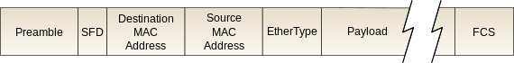
An Ethernet frame is preceded by a preamble and start frame delimiter (SFD), which are both part of the Ethernet packet at the physical layer. Each Ethernet frame starts with an Ethernet header, which contains destination and source MAC addresses as its first two fields. The middle section of the frame is payload data including any headers for other protocols (for example, Internet Protocol) carried in the frame. The frame ends with a frame check sequence (FCS), which is a 32-bit cyclic redundancy check used to detect any in-transit corruption of data.
Structure
A data packet on the wire and the frame as its payload consist of binary data. Ethernet transmits data with the most-significant octet (byte) first; within each octet, however, the least-significant bit is transmitted first.[lower-alpha 1]
The internal structure of an Ethernet frame is specified in IEEE 802.3.[1] The table below shows the complete Ethernet packet and the frame inside, as transmitted, for the payload size up to the MTU of 1500 octets.[lower-alpha 2] Some implementations of Gigabit Ethernet and other higher-speed variants of Ethernet support larger frames, known as jumbo frames.
| Layer | Preamble | Start of frame delimiter | MAC destination | MAC source | 802.1Q tag (optional) | Ethertype (Ethernet II) or length (IEEE 802.3) | Payload | Frame check sequence (32‑bit CRC) | Interpacket gap |
|---|---|---|---|---|---|---|---|---|---|
| 7 octets | 1 octet | 6 octets | 6 octets | (4 octets) | 2 octets | 46‑1500 octets | 4 octets | 12 octets | |
| Layer 2 Ethernet frame | ← 64–1522 octets → | ||||||||
| Layer 1 Ethernet packet & IPG | ← 72–1530 octets → | ← 12 octets → | |||||||
The optional 802.1Q tag consumes additional space in the frame. Field sizes for this option are shown in brackets in the table above. IEEE 802.1ad (Q-in-Q) allows for multiple tags in each frame. This option is not illustrated here.
Ethernet packet – physical layer
Preamble and start frame delimiter
An Ethernet packet starts with a seven-octet preamble and one-octet start frame delimiter (SFD).[lower-alpha 3]
The preamble consists of a 56-bit (seven-byte) pattern of alternating 1 and 0 bits, allowing devices on the network to easily synchronize their receiver clocks, providing bit-level synchronization. It is followed by the SFD to provide byte-level synchronization and to mark a new incoming frame. For Ethernet variants transmitting serial bits instead of larger symbols, the (uncoded) on-the-wire bit pattern for the preamble together with the SFD portion of the frame is 10101010 10101010 10101010 10101010 10101010 10101010 10101010 10101011;[3]:sections 4.2.5 and 3.2.2 The bits are transmitted in order, from left to right.[3]:sections 4.2.5
The SFD is the eight-bit (one-byte) value that marks the end of the preamble, which is the first field of an Ethernet packet, and indicates the beginning of the Ethernet frame. The SFD is designed to break the bit pattern of the preamble and signal the start of the actual frame.[3]:section 4.2.5 The SFD is immediately followed by the destination MAC address, which is the first field in an Ethernet frame. SFD is the binary sequence 10101011 (0xD5, decimal 213 in the Ethernet LSB first bit ordering).[3]:sections 3.2.2, 3.3 and 4.2.6
Physical layer transceiver circuitry (PHY for short) is required to connect the Ethernet MAC to the physical medium. The connection between a PHY and MAC is independent of the physical medium and uses a bus from the media independent interface family (MII, GMII, RGMII, SGMII, XGMII). Fast Ethernet transceiver chips utilize the MII bus, which is a four-bit (one nibble) wide bus, therefore the preamble is represented as 14 instances of 0x5, and the SFD is 0x5 0xD (as nibbles). Gigabit Ethernet transceiver chips use the GMII bus, which is an eight-bit wide interface, so the preamble sequence followed by the SFD would be 0x55 0x55 0x55 0x55 0x55 0x55 0x55 0xD5 (as bytes).
Frame – data link layer
Header
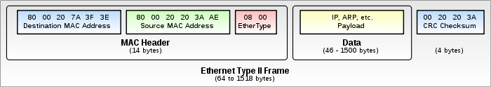
The header features destination and source MAC addresses (each six octets in length), the EtherType field and, optionally, an IEEE 802.1Q tag or IEEE 802.1ad tag.
The EtherType field is two octets long and it can be used for two different purposes. Values of 1500 and below mean that it is used to indicate the size of the payload in octets, while values of 1536 and above indicate that it is used as an EtherType, to indicate which protocol is encapsulated in the payload of the frame. When used as EtherType, the length of the frame is determined by the location of the interpacket gap and valid frame check sequence (FCS).
The IEEE 802.1Q tag or IEEE 802.1ad tag, if present, is a four-octet field that indicates virtual LAN (VLAN) membership and IEEE 802.1p priority. The first two octets of the tag are called the Tag Protocol IDentifier and double as the EtherType field indicating that the frame is either 802.1Q or 802.1ad tagged. 802.1Q uses a TPID of 0x8100. 802.1ad uses a TPID of 0x88a8.
Payload
The minimum payload is 42 octets when an 802.1Q tag is present and 46 octets when absent.[lower-alpha 4] When the actual payload is less, padding bytes are added accordingly.[lower-alpha 5] The maximum payload is 1500 octets. Non-standard jumbo frames allow for larger maximum payload size.
Frame check sequence
The frame check sequence (FCS) is a four-octet cyclic redundancy check (CRC) that allows detection of corrupted data within the entire frame as received on the receiver side. The FCS value is computed as a function of the protected MAC frame fields: source and destination address, length/type field, MAC client data and padding (that is, all fields except the FCS).[3]:section 3.2.9
Running the CRC algorithm over the received frame data including the CRC code will always result in a zero value for error-free received data, because the CRC is a remainder of the data divided by the polynomial. However, this technique can result in "false negatives", in which data with trailing zeroes will also result in the same zero remainder. To avoid this scenario, the FCS is complemented (reversed for each bit) by the sender before it is attached to the end of the payload data.[3]:section 3.2.9 This way, the algorithm result will always be a magic number or CRC32 residue of 0xC704DD7B when data has been received correctly. This allows for receiving a frame and validating the FCS without knowing where the FCS field actually starts.[5][6]
End of frame – physical layer
The end of a frame is usually indicated by the end-of-data-stream symbol at the physical layer or by loss of the carrier signal; an example is 10BASE-T, where the receiving station detects the end of a transmitted frame by loss of the carrier. Later physical layers use an explicit end of data or end of stream symbol or sequence to avoid ambiguity, especially where the carrier is continually sent between frames; an example is Gigabit Ethernet with its 8b/10b encoding scheme that uses special symbols which are transmitted before and after a frame is transmitted.[7][8]
Interpacket gap – physical layer
Interpacket gap is idle time between packets. After a packet has been sent, transmitters are required to transmit a minimum of 96 bits (12 octets) of idle line state before transmitting the next packet.
Types
| Frame type | Ethertype or length | Payload start two bytes |
|---|---|---|
| Ethernet II | ≥ 1536 | Any |
| Novell raw IEEE 802.3 | ≤ 1500 | 0xFFFF |
| IEEE 802.2 LLC | ≤ 1500 | Other |
| IEEE 802.2 SNAP | ≤ 1500 | 0xAAAA |
There are several types of Ethernet frames:
- Ethernet II frame, or Ethernet Version 2,[lower-alpha 6] or DIX frame is the most common type in use today, as it is often used directly by the Internet Protocol.
- Novell raw IEEE 802.3 non-standard variation frame
- IEEE 802.2 Logical Link Control (LLC) frame
- IEEE 802.2 Subnetwork Access Protocol (SNAP) frame
The different frame types have different formats and MTU values, but can coexist on the same physical medium. Differentiation between frame types is possible based on the table on the right.
In addition, all four Ethernet frame types may optionally contain an IEEE 802.1Q tag to identify what VLAN it belongs to and its priority (quality of service). This encapsulation is defined in the IEEE 802.3ac specification and increases the maximum frame by 4 octets.
The IEEE 802.1Q tag, if present, is placed between the Source Address and the EtherType or Length fields. The first two octets of the tag are the Tag Protocol Identifier (TPID) value of 0x8100. This is located in the same place as the EtherType/Length field in untagged frames, so an EtherType value of 0x8100 means the frame is tagged, and the true EtherType/Length is located after the Q-tag. The TPID is followed by two octets containing the Tag Control Information (TCI) (the IEEE 802.1p priority (quality of service) and VLAN id). The Q-tag is followed by the rest of the frame, using one of the types described above.
Ethernet II
Ethernet II framing (also known as DIX Ethernet, named after DEC, Intel and Xerox, the major participants in its design[9]), defines the two-octet EtherType field in an Ethernet frame, preceded by destination and source MAC addresses, that identifies an upper layer protocol encapsulated by the frame data. For example, an EtherType value of 0x0800 signals that the frame contains an IPv4 datagram. Likewise, an EtherType of 0x0806 indicates an ARP frame, 0x86DD indicates an IPv6 frame and 0x8100 indicates the presence of an IEEE 802.1Q tag (as described above).
As this industry-developed standard went through a formal IEEE standardization process, the EtherType field was changed to a (data) length field in the new 802.3 standard.[lower-alpha 7] Since the recipient still needs to know how to interpret the frame, the standard required an IEEE 802.2 header to follow the length and specify the type. Many years later, the 802.3x-1997 standard, and later versions of the 802.3 standard, formally approved of both types of framing. Ethernet II framing is the most common in Ethernet local area networks, due to its simplicity and lower overhead.
In order to allow some frames using Ethernet v2 framing and some using the original version of 802.3 framing to be used on the same Ethernet segment, EtherType values must be greater than or equal to 1536 (0x0600). That value was chosen because the maximum length of the payload field of an Ethernet 802.3 frame is 1500 octets (0x05DC). Thus if the field's value is greater than or equal to 1536, the frame must be an Ethernet v2 frame, with that field being a type field.[10] If it's less than or equal to 1500, it must be an IEEE 802.3 frame, with that field being a length field. Values between 1500 and 1536, exclusive, are undefined.[11] This convention allows software to determine whether a frame is an Ethernet II frame or an IEEE 802.3 frame, allowing the coexistence of both standards on the same physical medium.
Novell raw IEEE 802.3
Novell's "raw" 802.3 frame format was based on early IEEE 802.3 work. Novell used this as a starting point to create the first implementation of its own IPX Network Protocol over Ethernet. They did not use any LLC header but started the IPX packet directly after the length field. This does not conform to the IEEE 802.3 standard, but since IPX always has FF as the first two octets (while in IEEE 802.2 LLC that pattern is theoretically possible but extremely unlikely), in practice this usually coexists on the wire with other Ethernet implementations, with the notable exception of some early forms of DECnet which got confused by this.
Novell NetWare used this frame type by default until the mid-nineties, and since NetWare was then very widespread, while IP was not, at some point in time most of the world's Ethernet traffic ran over "raw" 802.3 carrying IPX. Since NetWare 4.10, NetWare defaults to IEEE 802.2 with LLC (NetWare Frame Type Ethernet_802.2) when using IPX.[12]
IEEE 802.2 LLC
Some protocols, those designed for the OSI stack, operate directly on top of IEEE 802.2 LLC encapsulation, which provides both connection-oriented and connectionless network services.
IEEE 802.2 LLC encapsulation is not in widespread use on common networks currently, with the exception of large corporate NetWare installations that have not yet migrated to NetWare over IP. In the past, many corporate networks used IEEE 802.2 to support transparent translating bridges between Ethernet and Token Ring or FDDI networks.
There exists an Internet standard for encapsulating IPv4 traffic in IEEE 802.2 LLC SAP/SNAP frames.[13] It is almost never implemented on Ethernet, although it is used on FDDI, Token Ring, IEEE 802.11 (with the exception of the 5.9 GHz band, where it uses EtherType)[14] and other IEEE 802 LANs. IPv6 can also be transmitted over Ethernet using IEEE 802.2 LLC SAP/SNAP, but, again, that's almost never used.
IEEE 802.2 SNAP
By examining the 802.2 LLC header, it is possible to determine whether it is followed by a SNAP header. The LLC header includes two eight-bit address fields, called service access points (SAPs) in OSI terminology; when both source and destination SAP are set to the value 0xAA, the LLC header is followed by a SNAP header. The SNAP header allows EtherType values to be used with all IEEE 802 protocols, as well as supporting private protocol ID spaces.
In IEEE 802.3x-1997, the IEEE Ethernet standard was changed to explicitly allow the use of the 16-bit field after the MAC addresses to be used as a length field or a type field.
Mac OS uses IEEE 802.2 LLC + SNAP encapsulation for the AppleTalk v2 protocol suite on Ethernet ("EtherTalk").
Maximum throughput
We may calculate the protocol overhead for Ethernet as a percentage (packet size including IPG)

We may calculate the protocol efficiency for Ethernet

Maximum efficiency is achieved with largest allowed payload size and is:

for untagged frames, since the packet size is maximum 1500 octet payload + 8 octet preamble + 14 octet header + 4 octet trailer + minimum interpacket gap corresponding to 12 octets = 1538 octets. The maximum efficiency is:

when 802.1Q VLAN tagging is used.
The throughput may be calculated from the efficiency
- ,

where the physical layer net bit rate (the wire bit rate) depends on the Ethernet physical layer standard, and may be 10 Mbit/s, 100 Mbit/s, 1 Gbit/s or 10 Gbit/s. Maximum throughput for 100BASE-TX Ethernet is consequently 97.53 Mbit/s without 802.1Q, and 97.28 Mbit/s with 802.1Q.
Channel utilization is a concept often confused with protocol efficiency. It considers only the use of the channel disregarding the nature of the data transmitted – either payload or overhead. At the physical layer, the link channel and equipment do not know the difference between data and control frames. We may calculate the channel utilization:

The total time considers the round trip time along the channel, the processing time in the hosts and the time transmitting data and acknowledgements. The time spent transmitting data includes data and acknowledgements.
Runt frames
A runt frame is an Ethernet frame that is less than the IEEE 802.3's minimum length of 64 octets. Runt frames are most commonly caused by collisions; other possible causes are a malfunctioning network card, buffer underrun, duplex mismatch or software issues.[15]
Notes
- ↑ The frame check sequence (FCS) uses a different bit ordering.[2]
- ↑ The bit patterns in the preamble and start of frame delimiter are written as bit strings, with the first bit transmitted on the left (not as octet values, which in Ethernet are transmitted least significant bit(s) first). This notation matches the one used in the IEEE 802.3 standard.
- ↑ Preamble and start frame delimiter are not displayed by packet sniffing software because these bits are stripped away at OSI layer 1 by the network interface controller (NIC) before being passed on to the OSI layer 2, which is where packet sniffers collect their data. There are layer-2 sniffers that can capture and display the preamble and start frame delimiter, but they are expensive and mainly used to detect problems related to physical connectivity.
- ↑ Minimum payload size is dictated by the 512-bit slot time used for collision detection in the Ethernet LAN architecture.
- ↑ Both 42 and 46 octet minimums are valid when 802.1Q is present.[4]
- ↑ A version 1 Ethernet frame was used for early Ethernet prototypes and featured 8-bit MAC addresses and was never commercially deployed.
- ↑ Original Ethernet frames define their length with the framing that surrounds it, rather than with an explicit length count.
References
- 1 2 "3.1.1 Packet format" (PDF). IEEE Standard for Ethernet, 802.3-2015 – section one. 2016. p. 108. Retrieved 2018-04-12.
- ↑ "802.3-2012 – IEEE Standard for Ethernet" (PDF). ieee.org. IEEE Standards Association. 2012-12-28. section 3.3 and annex 31A. Retrieved 2014-02-09.
Opcodes are transmitted high-order octet first. Within each octet, bits are transmitted least-significant bit first. [...] Each octet of the MAC frame, with the exception of the FCS, is transmitted least significant bit first.
- 1 2 3 4 5 6 7 "802.3-2012 – IEEE Standard for Ethernet" (PDF). ieee.org. IEEE Standards Association. 2012-12-28. Retrieved 2014-02-09.
- ↑ IEEE 802.1Q-2011, Annex G
- ↑ "Cyclic Redundancy Check" (PDF). hackersdelight.org. 28 July 2009. Archived from the original (PDF) on 3 May 2015. Retrieved 2 June 2015.
- ↑ Nanditha Jayarajan (2007-04-20). "Configurable LocalLink CRC Reference Design" (PDF). xilinx.com. p. 14. Retrieved 2014-06-30.
- ↑ Charles E. Spurgeon (February 2000). Ethernet: The Definitive Guide. O'Reilly. pp. 41, 47. Retrieved 2014-06-30.
- ↑ "40.1.3.1 Physical Coding Sublayer (PCS)" (PDF). IEEE Standard for Ethernet, 802.3-2012 – section three. 2012-12-28. p. 183. Retrieved 2014-07-06.
- ↑ Drew Heywood; Zubair Ahmad (2001). Drew Heywood's Windows 2000 Network Services. Sams. p. 53. ISBN 0-672-31741-9.
- ↑ LAN MAN Standards Committee of the IEEE Computer Society (20 March 1997). IEEE Std 802.3x-1997 and IEEE Std 802.3y-1997. The Institute of Electrical and Electronics Engineers, Inc. pp. 28–31.
- ↑ IEEE Std 802.3-2005, 3.2.6
- ↑ Don Provan (17 September 1993). "Ethernet Framing". Newsgroup: comp.sys.novell. Usenet: 1993Sep17.190654.13335@novell.com. (HTML-formatted version Archived 18 April 2015 at the Wayback Machine.) — a classic series of Usenet postings by Novell's Don Provan that have found their way into numerous FAQs and are widely considered the definitive answer to the Novell Frame Type usage.
- ↑ "RFC1042: A Standard for the Transmission of IP Datagrams over IEEE 802 Networks". Network Working Group of the IETF. February 1988.
- ↑ Computer Society, IEEE (2016). IEEE Std 802.11-2016: Part 11: Wireless LAN Medium Access Control IEEE (MAC) and Physical Layer (PHY) Specifications. New York, NY: IEEE. p. 249.
- ↑ "Troubleshooting Ethernet". Cisco Systems. Retrieved 2016-08-13.
Further reading
| Wikiversity has learning resources about Topic:Web Science/Part1: Foundations of the web/Internet Architecture/Ethernet |