IPv4
Internet Protocol version 4 (IPv4) is the fourth version of the Internet Protocol (IP). It is one of the core protocols of standards-based internetworking methods in the Internet, and was the first version deployed for production in the ARPANET in 1983. It still routes most Internet traffic today,[1] despite the ongoing deployment of a successor protocol, IPv6. IPv4 is described in IETF publication RFC 791 (September 1981), replacing an earlier definition (RFC 760, January 1980).
IPv4 is a connectionless protocol for use on packet-switched networks. It operates on a best effort delivery model, in that it does not guarantee delivery, nor does it assure proper sequencing or avoidance of duplicate delivery. These aspects, including data integrity, are addressed by an upper layer transport protocol, such as the Transmission Control Protocol (TCP).
| Internet protocol suite |
|---|
| Application layer |
| Transport layer |
| Internet layer |
| Link layer |
Addressing
IPv4 uses 32-bit addresses which limits the address space to 4294967296 (232) addresses.
IPv4 reserves special address blocks for private networks (~18 million addresses) and multicast addresses (~270 million addresses).
Address representations
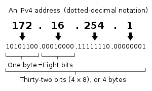
IPv4 addresses may be represented in any notation expressing a 32-bit integer value. They are most often written in the dot-decimal notation, which consists of four octets of the address expressed individually in decimal numbers and separated by periods.
For example, the quad-dotted IP address 192.0.2.235 represents the 32-bit decimal number 3221226219, which in hexadecimal format is 0xC00002EB. This may also be expressed in dotted hex format as 0xC0.0x00.0x02.0xEB, or with octal byte values as 0300.0000.0002.0353.
CIDR notation combines the address with its routing prefix in a compact format, in which the address is followed by a slash character (/) and the count of consecutive 1 bits in the routing prefix (subnet mask).
Allocation
In the original design of IPv4, an IP address was divided into two parts: the network identifier was the most significant octet of the address, and the host identifier was the rest of the address. The latter was also called the rest field. This structure permitted a maximum of 256 network identifiers, which was quickly found to be inadequate.
To overcome this limit, the most-significant address octet was redefined in 1981 to create network classes, in a system which later became known as classful networking. The revised system defined five classes. Classes A, B, and C had different bit lengths for network identification. The rest of the address was used as previously to identify a host within a network. Because of the different sizes of fields in different classes, each network class had a different capacity for addressing hosts. In addition to the three classes for addressing hosts, Class D was defined for multicast addressing and Class E was reserved for future applications.
Starting around 1985, methods were devised to subdivide IP networks. One method that has proved flexible is the use of the variable-length subnet mask (VLSM).[2][3] Based on the IETF standard RFC 1517 published in 1993, this system of classes was officially replaced with Classless Inter-Domain Routing (CIDR), which expressed the number of bits (from the most significant) as, for instance, /24, and the class-based scheme was dubbed classful, by contrast. CIDR was designed to permit repartitioning of any address space so that smaller or larger blocks of addresses could be allocated to users. The hierarchical structure created by CIDR is managed by the Internet Assigned Numbers Authority (IANA) and the regional Internet registries (RIRs). Each RIR maintains a publicly searchable WHOIS database that provides information about IP address assignments.
Special-use addresses
The Internet Engineering Task Force (IETF) and the Internet Assigned Numbers Authority (IANA) have restricted from general use various reserved IP addresses for special purposes. Some are used for maintenance of routing tables, for multicast traffic, operation under failure modes, or to provide addressing space for public, unrestricted uses on private networks.
Special address blocks Address block Address range Number of addresses Scope Description 0.0.0.0/8 0.0.0.0–0.255.255.255 16777216 (224) Software Current network[4] (only valid as source address). 10.0.0.0/8 10.0.0.0–10.255.255.255 16777216 Private network Used for local communications within a private network.[5] 100.64.0.0/10 100.64.0.0–100.127.255.255 4194304 Private network Shared address space[6] for communications between a service provider and its subscribers when using a carrier-grade NAT. 127.0.0.0/8 127.0.0.0–127.255.255.255 16777216 Host Used for loopback addresses to the local host.[4] 169.254.0.0/16 169.254.0.0–169.254.255.255 65536 Subnet Used for link-local addresses[7] between two hosts on a single link when no IP address is otherwise specified, such as would have normally been retrieved from a DHCP server. 172.16.0.0/12 172.16.0.0–172.31.255.255 1048576 Private network Used for local communications within a private network.[5] 192.0.0.0/24 192.0.0.0–192.0.0.255 256 Private network IETF Protocol Assignments.[4] 192.0.2.0/24 192.0.2.0–192.0.2.255 256 Documentation Assigned as TEST-NET-1, documentation and examples.[8] 192.88.99.0/24 192.88.99.0–192.88.99.255 256 Internet Reserved.[9] Formerly used for IPv6 to IPv4 relay[10] (included IPv6 address block 2002::/16). 192.168.0.0/16 192.168.0.0–192.168.255.255 65536 Private network Used for local communications within a private network.[5] 198.18.0.0/15 198.18.0.0–198.19.255.255 131072 Private network Used for benchmark testing of inter-network communications between two separate subnets.[11] 198.51.100.0/24 198.51.100.0–198.51.100.255 256 Documentation Assigned as TEST-NET-2, documentation and examples.[8] 203.0.113.0/24 203.0.113.0–203.0.113.255 256 Documentation Assigned as TEST-NET-3, documentation and examples.[8] 224.0.0.0/4 224.0.0.0–239.255.255.255 268435456 Internet In use for IP multicast.[12] (Former Class D network). 240.0.0.0/4 240.0.0.0–255.255.255.254 268435456 Internet Reserved for future use.[13] (Former Class E network). 255.255.255.255/32 255.255.255.255 1 Subnet Reserved for the "limited broadcast" destination address.[4][14]
Private networks
Of the approximately four billion addresses defined in IPv4, three ranges are reserved for use in private networks. Packets addresses in these ranges are not routable in the public Internet, because they are ignored by all public routers. Therefore, private hosts cannot directly communicate with public networks, but require network address translation at a routing gateway for this purpose.
Name CIDR block Address range Number of addresses Classful description 24-bit block 10.0.0.0/8 10.0.0.0 – 10.255.255.255 16777216 Single Class A. 20-bit block 172.16.0.0/12 172.16.0.0 – 172.31.255.255 1048576 Contiguous range of 16 Class B blocks. 16-bit block 192.168.0.0/16 192.168.0.0 – 192.168.255.255 65536 Contiguous range of 256 Class C blocks.
Since two private networks, e.g., two branch offices, cannot directly interoperate via the public Internet, the two networks must be bridged across the Internet via a virtual private network (VPN) or an IP tunnel, which encapsulate the packet in a protocol layer during transmission across the public network. Additionally, encapsulated packets may be encrypted for the transmission across public networks to secure the data.
Link-local addressing
RFC 3927 defines the special address block 169.254.0.0/16 for link-local addressing. These addresses are only valid on links (such as a local network segment or point-to-point connection) connected to a host. These addresses are not routable. Like private addresses, these addresses cannot be the source or destination of packets traversing the internet. These addresses are primarily used for address autoconfiguration (Zeroconf) when a host cannot obtain an IP address from a DHCP server or other internal configuration methods.
When the address block was reserved, no standards existed for address autoconfiguration. Microsoft created an implementation called Automatic Private IP Addressing (APIPA), which was deployed on millions of machines and became a de facto standard. Many years later, in May 2005, the IETF defined a formal standard in RFC 3927, entitled Dynamic Configuration of IPv4 Link-Local Addresses.
Loopback
The class A network 127.0.0.0 (classless network 127.0.0.0/8) is reserved for loopback. IP packets whose source addresses belong to this network should never appear outside a host. The modus operandi of this network expands upon that of a loopback interface:
- IP packets whose source and destination addresses belong to the network (or subnetwork) of the same loopback interface are returned to that interface;
- IP packets whose source and destination addresses belong to networks (or subnetworks) of different interfaces of the same host, one of them being a loopback interface, are forwarded regularly.
Addresses ending in 0 or 255
Networks with subnet masks of at least 24 bits, i.e. Class C networks in classful networking, and networks with CIDR suffixes /24 to /30 (255.255.255.0–255.255.255.252) may not have an address ending in 0 or 255.
Classful addressing prescribed only three possible subnet masks: Class A, 255.0.0.0 or /8; Class B, 255.255.0.0 or /16; and Class C, 255.255.255.0 or /24. For example, in the subnet 192.168.5.0/255.255.255.0 (192.168.5.0/24) the identifier 192.168.5.0 commonly is used to refer to the entire subnet. To avoid ambiguity in representation, the address ending in the octet 0 is reserved.
A broadcast address[1] is an address that allows information to be sent to all interfaces in a given subnet, rather than a specific machine. Generally, the broadcast address is found by obtaining the bit complement of the subnet mask and performing a bitwise OR operation with the network identifier. In other words, the broadcast address is the last address in the address range of the subnet. For example, the broadcast address for the network 192.168.5.0 is 192.168.5.255. For networks of size /24 or larger, the broadcast address always ends in 255.
| Binary form | Dot-decimal notation | |
|---|---|---|
| Network space | 11000000.10101000.00000101.00000000 |
192.168.5.0 |
| Broadcast address | 11000000.10101000.00000101.11111111 |
192.168.5.255 |
| In bold, is shown the host part of the IP; the other part is the network prefix. The host gets inverted (logical NOT), but the network prefix remains intact. | ||
However, this does not mean that every address ending in 0 or 255 cannot be used as a host address. For example, in the /16 subnet 192.168.0.0/255.255.0.0, which is equivalent to the address range 192.168.0.0–192.168.255.255, the broadcast address is 192.168.255.255. One can use the following addresses for hosts, even though they end with 255: 192.168.1.255, 192.168.2.255, etc. Also, 192.168.0.0 is the network identifier and must not be assigned to an interface.[15] The addresses 192.168.1.0, 192.168.2.0, etc., may be assigned, despite ending with 0.
In the past, conflict between network addresses and broadcast addresses arose because some software used non-standard broadcast addresses with zeros instead of ones.[16]
In networks smaller than /24, broadcast addresses do not necessarily end with 255. For example, a CIDR subnet 203.0.113.16/28 has the broadcast address 203.0.113.31.
| Binary form | Dot-decimal notation | |
|---|---|---|
| Network space | 11001011.00000000.01110001.00010000 |
203.0.113.16 |
| Broadcast address | 11001011.00000000.01110001.00011111 |
203.0.113.31 |
| In bold, is shown the host part of the IP; the other part is the network prefix. The host gets inverted (logical NOT), but the network prefix remains intact. | ||
Address resolution
Hosts on the Internet are usually known by names, e.g., www.example.com, not primarily by their IP address, which is used for routing and network interface identification. The use of domain names requires translating, called resolving, them to addresses and vice versa. This is analogous to looking up a phone number in a phone book using the recipient's name.
The translation between addresses and domain names is performed by the Domain Name System (DNS), a hierarchical, distributed naming system which allows for subdelegation of name spaces to other DNS servers.
Address space exhaustion
Since the 1980s, it was apparent that the pool of available IPv4 addresses was being depleted at a rate that was not initially anticipated in the original design of the network address system.[17] The main market forces which accelerated IPv4 address depletion included:
- Rapidly growing number of Internet users
- Always-on devices — ADSL modems, cable modems
- Mobile devices — laptop computers, PDAs, mobile phones.
The threat of exhaustion motivated the introduction of a number of remedial technologies, such as classful networks, Classless Inter-Domain Routing (CIDR) methods, network address translation (NAT) and strict usage-based allocation policies. To provide a long-term solution to the pending address exhaustion, IPv6 was created in the 1990s, which made many more addresses available by increasing the address size to 128 bits. IPv6 has been in commercial deployment since 2006.
The primary address pool of the Internet, maintained by IANA, was exhausted on 3 February 2011, when the last 5 blocks were allocated to the 5 RIRs.[18][19] APNIC was the first RIR to exhaust its regional pool on 15 April 2011, except for a small amount of address space reserved for the transition to IPv6, which will be allocated under a much more restricted policy.[20]
The accepted and standard long term solution is to use IPv6 which increased the address size to 128 bits, providing a vastly increased address space that also allows improved route aggregation across the Internet and offers large subnetwork allocations of a minimum of 264 host addresses to end-users. However IPv4-only hosts cannot directly communicate with IPv6-only hosts so IPv6 alone does not provide an immediate solution to the IPv4 exhaustion problem. Migration to IPv6 is in progress but completion is expected to take considerable time. [21]
Packet structure
An IP packet consists of a header section and a data section.
An IP packet has no data checksum or any other footer after the data section. Typically the link layer encapsulates IP packets in frames with a CRC footer that detects most errors, and typically the end-to-end TCP layer checksum detects most other errors.[22]
Header
The IPv4 packet header consists of 14 fields, of which 13 are required. The 14th field is optional and aptly named: options. The fields in the header are packed with the most significant byte first (big endian), and for the diagram and discussion, the most significant bits are considered to come first (MSB 0 bit numbering). The most significant bit is numbered 0, so the version field is actually found in the four most significant bits of the first byte, for example.
| Offsets | Octet | 0 | 1 | 2 | 3 | ||||||||||||||||||||||||||||
|---|---|---|---|---|---|---|---|---|---|---|---|---|---|---|---|---|---|---|---|---|---|---|---|---|---|---|---|---|---|---|---|---|---|
| Octet | Bit | 0 | 1 | 2 | 3 | 4 | 5 | 6 | 7 | 8 | 9 | 10 | 11 | 12 | 13 | 14 | 15 | 16 | 17 | 18 | 19 | 20 | 21 | 22 | 23 | 24 | 25 | 26 | 27 | 28 | 29 | 30 | 31 |
| 0 | 0 | Version | IHL | DSCP | ECN | Total Length | |||||||||||||||||||||||||||
| 4 | 32 | Identification | Flags | Fragment Offset | |||||||||||||||||||||||||||||
| 8 | 64 | Time To Live | Protocol | Header Checksum | |||||||||||||||||||||||||||||
| 12 | 96 | Source IP Address | |||||||||||||||||||||||||||||||
| 16 | 128 | Destination IP Address | |||||||||||||||||||||||||||||||
| 20 | 160 | Options (if IHL > 5) | |||||||||||||||||||||||||||||||
| 24 | 192 | ||||||||||||||||||||||||||||||||
| 28 | 224 | ||||||||||||||||||||||||||||||||
| 32 | 256 | ||||||||||||||||||||||||||||||||
- Version
- The first header field in an IP packet is the four-bit version field. For IPv4, this is always equal to 4.
- Internet Header Length (IHL)
- The Internet Header Length (IHL) field has 4 bits, which is the number of 32-bit words. Since an IPv4 header may contain a variable number of options, this field specifies the size of the header (this also coincides with the offset to the data). The minimum value for this field is 5,[23] which indicates a length of 5 × 32 bits = 160 bits = 20 bytes. As a 4-bit field, the maximum value is 15 words (15 × 32 bits, or 480 bits = 60 bytes).
- Differentiated Services Code Point (DSCP)
- Originally defined as the type of service (ToS), this field specifies differentiated services (DiffServ) per RFC 2474 (updated by RFC 3168 and RFC 3260). New technologies are emerging that require real-time data streaming and therefore make use of the DSCP field. An example is Voice over IP (VoIP), which is used for interactive voice services.
- Explicit Congestion Notification (ECN)
- This field is defined in RFC 3168 and allows end-to-end notification of network congestion without dropping packets. ECN is an optional feature that is only used when both endpoints support it and are willing to use it. It is only effective when supported by the underlying network.
- Total Length
- This 16-bit field defines the entire packet size in bytes, including header and data. The minimum size is 20 bytes (header without data) and the maximum is 65,535 bytes. All hosts are required to be able to reassemble datagrams of size up to 576 bytes, but most modern hosts handle much larger packets. Sometimes links impose further restrictions on the packet size, in which case datagrams must be fragmented. Fragmentation in IPv4 is handled in either the host or in routers.
- Identification
- This field is an identification field and is primarily used for uniquely identifying the group of fragments of a single IP datagram. Some experimental work has suggested using the ID field for other purposes, such as for adding packet-tracing information to help trace datagrams with spoofed source addresses,[24] but RFC 6864 now prohibits any such use.
- Flags
- A three-bit field follows and is used to control or identify fragments. They are (in order, from most significant to least significant):
- bit 0: Reserved; must be zero.[note 1]
- bit 1: Don't Fragment (DF)
- bit 2: More Fragments (MF)
If the DF flag is set, and fragmentation is required to route the packet, then the packet is dropped. This can be used when sending packets to a host that does not have resources to handle fragmentation. It can also be used for path MTU discovery, either automatically by the host IP software, or manually using diagnostic tools such as ping or traceroute.
For unfragmented packets, the MF flag is cleared. For fragmented packets, all fragments except the last have the MF flag set. The last fragment has a non-zero Fragment Offset field, differentiating it from an unfragmented packet. - Fragment Offset
- The fragment offset field is measured in units of eight-byte blocks. It is 13 bits long and specifies the offset of a particular fragment relative to the beginning of the original unfragmented IP datagram. The first fragment has an offset of zero. This allows a maximum offset of (213 – 1) × 8 = 65,528 bytes, which would exceed the maximum IP packet length of 65,535 bytes with the header length included (65,528 + 20 = 65,548 bytes).
- Time To Live (TTL)
- An eight-bit time to live field helps prevent datagrams from persisting (e.g. going in circles) on an internet. This field limits a datagram's lifetime. It is specified in seconds, but time intervals less than 1 second are rounded up to 1. In practice, the field has become a hop count—when the datagram arrives at a router, the router decrements the TTL field by one. When the TTL field hits zero, the router discards the packet and typically sends an ICMP Time Exceeded message to the sender. The program traceroute uses these ICMP Time Exceeded messages to print the routers used by packets to go from the source to the destination.
- Protocol
- This field defines the protocol used in the data portion of the IP datagram. The Internet Assigned Numbers Authority maintains a list of IP protocol numbers as directed by RFC 790.
- Header Checksum
- The 16-bit IPv4 header checksum field is used for error-checking of the header. When a packet arrives at a router, the router calculates the checksum of the header and compares it to the checksum field. If the values do not match, the router discards the packet. Errors in the data field must be handled by the encapsulated protocol. Both UDP and TCP have checksum fields. When a packet arrives at a router, the router decreases the TTL field. Consequently, the router must calculate a new checksum.
- Source address
- This field is the IPv4 address of the sender of the packet. Note that this address may be changed in transit by a network address translation device.
- Destination address
- This field is the IPv4 address of the receiver of the packet. As with the source address, this may be changed in transit by a network address translation device.
- Options
- The options field is not often used. Note that the value in the IHL field must include enough extra 32-bit words to hold all the options (plus any padding needed to ensure that the header contains an integer number of 32-bit words). The list of options may be terminated with an EOL (End of Options List, 0x00) option; this is only necessary if the end of the options would not otherwise coincide with the end of the header. The possible options that can be put in the header are as follows:
Field Size (bits) Description Copied 1 Set to 1 if the options need to be copied into all fragments of a fragmented packet. Option Class 2 A general options category. 0 is for "control" options, and 2 is for "debugging and measurement". 1 and 3 are reserved. Option Number 5 Specifies an option. Option Length 8 Indicates the size of the entire option (including this field). This field may not exist for simple options. Option Data Variable Option-specific data. This field may not exist for simple options. - Note: If the header length is greater than 5 (i.e., it is from 6 to 15) it means that the options field is present and must be considered.
- Note: Copied, Option Class, and Option Number are sometimes referred to as a single eight-bit field, the Option Type.
Packets containing some options may be considered as dangerous by some routers and be blocked.[25]
Data
The packet payload is not included in the checksum. Its contents are interpreted based on the value of the Protocol header field.
Some of the common payload protocols are:
| Protocol Number | Protocol Name | Abbreviation |
|---|---|---|
| 1 | Internet Control Message Protocol | ICMP |
| 2 | Internet Group Management Protocol | IGMP |
| 6 | Transmission Control Protocol | TCP |
| 17 | User Datagram Protocol | UDP |
| 41 | IPv6 encapsulation | ENCAP |
| 89 | Open Shortest Path First | OSPF |
| 132 | Stream Control Transmission Protocol | SCTP |
See List of IP protocol numbers for a complete list.
Fragmentation and reassembly
The Internet Protocol enables traffic between networks. The design accommodates networks of diverse physical nature; it is independent of the underlying transmission technology used in the Link Layer. Networks with different hardware usually vary not only in transmission speed, but also in the maximum transmission unit (MTU). When one network wants to transmit datagrams to a network with a smaller MTU, it may fragment its datagrams. In IPv4, this function was placed at the Internet Layer, and is performed in IPv4 routers, which thus require no implementation of any higher layers for the function of routing IP packets.
In contrast, IPv6, the next generation of the Internet Protocol, does not allow routers to perform fragmentation; hosts must determine the path MTU before sending datagrams.
Fragmentation
When a router receives a packet, it examines the destination address and determines the outgoing interface to use and that interface's MTU. If the packet size is bigger than the MTU, and the Do not Fragment (DF) bit in the packet's header is set to 0, then the router may fragment the packet.
The router divides the packet into fragments. The max size of each fragment is the MTU minus the IP header size (20 bytes minimum; 60 bytes maximum). The router puts each fragment into its own packet, each fragment packet having following changes:
- The total length field is the fragment size.
- The more fragments (MF) flag is set for all fragments except the last one, which is set to 0.
- The fragment offset field is set, based on the offset of the fragment in the original data payload. This is measured in units of eight-byte blocks.
- The header checksum field is recomputed.
For example, for an MTU of 1,500 bytes and a header size of 20 bytes, the fragment offsets would be multiples of . These multiples are 0, 185, 370, 555, 740, ...

It is possible that a packet is fragmented at one router, and that the fragments are further fragmented at another router. For example, a packet of 4,520 bytes, including the 20 bytes of the IP header (without options) is fragmented to two packets on a link with an MTU of 2,500 bytes:
| Fragment | Total bytes | Header bytes | Data bytes | "More fragments" flag | Fragment offset (8-byte blocks) |
|---|---|---|---|---|---|
| 1 | 2500 | 20 | 2480 | 1 | 0 |
| 2 | 2040 | 20 | 2020 | 0 | 310 |
The total data size is preserved: 2480 bytes + 2020 bytes = 4500 bytes. The offsets are and .


On a link with an MTU of 1,500 bytes, each fragment results in two fragments:
| Fragment | Total bytes | Header bytes | Data bytes | "More fragments" flag | Fragment offset (8-byte blocks) |
|---|---|---|---|---|---|
| 1 | 1500 | 20 | 1480 | 1 | 0 |
| 2 | 1020 | 20 | 1000 | 1 | 185 |
| 3 | 1500 | 20 | 1480 | 1 | 310 |
| 4 | 560 | 20 | 540 | 0 | 495 |
Again, the data size is preserved: 1480 + 1000 = 2480, and 1480 + 540 = 2020.
Also in this case, the More Fragments bit remains 1 for all the fragments that came with 1 in them and for the last fragment that arrives, it works as usual, that is the MF bit is set to 0 only in the last one. And of course, the Identification field continues to have the same value in all re-fragmented fragments. This way, even if fragments are re-fragmented, the receiver knows they have initially all started from the same packet.
The last offset and last data size are used to calculate the total data size: .

Reassembly
A receiver knows that a packet is a fragment if at least one of the following conditions is true:
- The "more fragments" flag is set. (This is true for all fragments except the last.)
- The "fragment offset" field is nonzero. (This is true for all fragments except the first.)
The receiver identifies matching fragments using the foreign and local address, the protocol ID, and the identification field. The receiver reassembles the data from fragments with the same ID using both the fragment offset and the more fragments flag. When the receiver receives the last fragment (which has the "more fragments" flag set to 0), it can calculate the length of the original data payload, by multiplying the last fragment's offset by eight, and adding the last fragment's data size. In the example above, this calculation was 495*8 + 540 = 4500 bytes.
When the receiver has all fragments, they can be correctly ordered by using the offsets, and reassembled to yield the original data segment.
Assistive protocols
The Internet Protocol is the protocol that defines and enables internetworking at the Internet Layer and thus forms the Internet. It uses a logical addressing system. IP addresses are not tied in any permanent manner to hardware identifications and, indeed, a network interface can have multiple IP addresses. Hosts and routers need additional mechanisms to identify the relationship between device interfaces and IP addresses, in order to properly deliver an IP packet to the destination host on a link. The Address Resolution Protocol (ARP) performs this IP-address-to-hardware-address translation for IPv4. (A hardware address is also called a MAC address.) In addition, the reverse correlation is often necessary. For example, when an IP host is booted or connected to a network it needs to determine its IP address, unless an address is preconfigured by an administrator. Protocols for such inverse correlations exist in the Internet Protocol Suite. Currently used methods are Dynamic Host Configuration Protocol (DHCP), Bootstrap Protocol (BOOTP) and, infrequently, reverse ARP.
See also
Notes
- ↑ As an April Fools' joke, proposed for use in RFC 3514 as the "Evil bit".
References
- 1 2 "BGP Analysis Reports". Retrieved 2013-01-09.
- ↑ "Planning Classless Routing: TCP/IP". Technet.microsoft.com. 2003-03-28. Retrieved 2012-01-20.
- ↑ "HP Networking: switches, routers, wired, wireless, HP TippingPoint Security" (PDF). 3com.com. Retrieved 2012-01-20.
- 1 2 3 4 M. Cotton; L. Vegoda; R. Bonica; B. Haberman (April 2013). Special-Purpose IP Address Registries. Internet Engineering Task Force. doi:10.17487/RFC6890. BCP 153. RFC 6890. https://tools.ietf.org/html/rfc6890. Updated by RFC 8190.
- 1 2 3 Y. Rekhter; B. Moskowitz; D. Karrenberg; G. J. de Groot; E. Lear (February 1996). Address Allocation for Private Internets. Network Working Group. doi:10.17487/RFC1918. BCP 5. RFC 1918. https://tools.ietf.org/html/rfc1918. Updated by RFC 6761.
- ↑ J. Weil; V. Kuarsingh; C. Donley; C. Liljenstolpe; M. Azinger (April 2012). IANA-Reserved IPv4 Prefix for Shared Address Space. Internet Engineering Task Force (IETF). doi:10.17487/RFC6598. ISSN 2070-1721. BCP 153. RFC 6598. https://tools.ietf.org/html/rfc6598.
- ↑ S. Cheshire; B. Aboba; E. Guttman (May 2005). Dynamic Configuration of IPv4 Link-Local Addresses. Network Working Group. doi:10.17487/RFC3927. RFC 3927. https://tools.ietf.org/html/rfc3927.
- 1 2 3 J. Arkko; M. Cotton; L. Vegoda (January 2010). IPv4 Address Blocks Reserved for Documentation. Internet Engineering Task Force. doi:10.17487/RFC5737. ISSN 2070-1721. RFC 5737. https://tools.ietf.org/html/rfc5737.
- ↑ O. Troan (May 2015). B. Carpenter. ed. Deprecating the Anycast Prefix for 6to4 Relay Routers. Internet Engineering Task Force. doi:10.17487/RFC7526. BCP 196. RFC 7526. https://tools.ietf.org/html/rfc7526.
- ↑ C. Huitema (June 2001). An Anycast Prefix for 6to4 Relay Routers. Network Working Group. doi:10.17487/RFC3068. RFC 3068. https://tools.ietf.org/html/rfc3068. Obsoleted by RFC 7526.
- ↑ S. Bradner; J. McQuaid (March 1999). Benchmarking Methodology for Network Interconnect Devices. Network Working Group. doi:10.17487/RFC2544. RFC 2544. https://tools.ietf.org/html/rfc2544. Updated by: RFC 6201 and RFC 6815.
- ↑ M. Cotton; L. Vegoda; D. Meyer (March 2010). IANA Guidelines for IPv4 Multicast Address Assignments. Internet Engineering Task Force. doi:10.17487/RFC5771. BCP 51. RFC 5771. https://tools.ietf.org/html/rfc5771.
- ↑ J. Reynolds, ed. (January 2002). Assigned Numbers: RFC 1700 is Replaced by an On-line Database. Network Working Group. doi:10.17487/RFC3232. RFC 3232. https://tools.ietf.org/html/rfc3232. Obsoletes RFC 1700.
- ↑ Jeffrey Mogul (October 1984). Broadcasting Internet Datagrams. Network Working Group. doi:10.17487/RFC0919. RFC 919. https://tools.ietf.org/html/rfc919.
- ↑ Robert Braden (October 1989). "Requirements for Internet Hosts – Communication Layers". IETF. p. 31. RFC 1122.
- ↑ Robert Braden (October 1989). "Requirements for Internet Hosts – Communication Layers". IETF. p. 66. RFC 1122.
- ↑ "World 'running out of Internet addresses'". Archived from the original on 2011-01-25. Retrieved 2011-01-23.
- ↑ Smith, Lucie; Lipner, Ian (3 February 2011). "Free Pool of IPv4 Address Space Depleted". Number Resource Organization. Retrieved 3 February 2011.
- ↑ ICANN,nanog mailing list. "Five /8s allocated to RIRs – no unallocated IPv4 unicast /8s remain".
- ↑ Asia-Pacific Network Information Centre (15 April 2011). "APNIC IPv4 Address Pool Reaches Final /8". Archived from the original on 17 August 2011. Retrieved 15 April 2011.
- ↑ 2016 IEEE International Conference on Emerging Technologies and Innovative Business Practices for the Transformation of Societies (EmergiTech) : date, 3-6 Aug. 2016. University of Technology, Mauritius,, Institute of Electrical and Electronics Engineers,. Piscataway, NJ. ISBN 9781509007066. OCLC 972636788.
- ↑ RFC 1726 section 6.2
- ↑ Information Sciences Institute, University of Southern California (September 1981). "RFC 791". Internet Engineering Task Force. Retrieved July 12, 2016.
- ↑ Savage, Stefan. "Practical network support for IP traceback". Retrieved 2010-09-06.
- ↑ "Cisco unofficial FAQ". Retrieved 2012-05-10.
External links
| Wikiversity has learning resources about IPv4 |
- https://www.iana.org — Internet Assigned Numbers Authority (IANA)
- http://www.networksorcery.com/enp/protocol/ip.htm — IP Header Breakdown, including specific options
- RFC 3344 — IPv4 Mobility
- IPv6 vs. carrier-grade NAT/squeezing more out of IPv4
- RIPE report on address consumption as of October 2003
- Official current state of IPv4 /8 allocations, as maintained by IANA
- Dynamically generated graphs of IPv4 address consumption with predictions of exhaustion dates—Geoff Huston
- IP addressing in China and the myth of address shortage
- Countdown of remaining IPv4 available addresses (estimated)