Fast Ethernet
In computer networking, Fast Ethernet is a collective term for a number of Ethernet standards that carry traffic at the nominal rate of 100 Mbit/s (the earlier Ethernet speed was 10 Mbit/s). Of the Fast Ethernet standards, 100BASE-TX is by far the most common.
Fast Ethernet was introduced in 1995 as the IEEE 802.3u standard[1] and remained the fastest version of Ethernet for three years before the introduction of Gigabit Ethernet.[2] The acronym GE/FE is sometimes used for devices supporting both standards.[3]
Nomenclature
The "100" in the media type designation refers to the transmission speed of 100 Mbit/s, while the "BASE" refers to baseband signalling. The letter following the dash ("T" or "F") refers to the physical medium that carries the signal (twisted pair or fiber, respectively), while the last character ("X", "4", etc.) refers to the line code method used. Fast Ethernet is sometimes referred to as 100BASE-X, where "X" is a placeholder for the FX and TX variants.[4]
General design
Fast Ethernet is an extension of the 10-megabit Ethernet standard. It runs on UTP data or optical fiber cable in a star wired bus topology, similar to 10BASE-T where all cables are attached to a hub. Fast Ethernet devices are generally backward compatible with existing 10BASE-T systems, enabling plug-and-play upgrades from 10BASE-T. The standard specifies the use of CSMA/CD for media access control. A full-duplex mode is also specified and in practice all modern networks use Ethernet switches and operate in full-duplex mode.
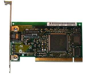
A Fast Ethernet adapter can be logically divided into a media access controller (MAC), which deals with the higher-level issues of medium availability, and a physical layer interface (PHY). The MAC is typically linked to the PHY by a four-bit 25 MHz synchronous parallel interface known as a media-independent interface (MII), or by a two-bit 50 MHz variant called reduced media independent interface (RMII). In rare cases the MII may be an external connection but is usually a connection between ICs in a network adapter or even two sections within a single IC. The specs are written based on the assumption that the interface between MAC and PHY will be a MII but they do not require it. Ethernet hubs may use the MII to connect to multiple PHYs for their different interfaces.
The MII fixes the theoretical maximum data bit rate for all versions of Fast Ethernet to 100 Mbit/s. The information rate actually observed on real networks is less than the theoretical maximum, due to the necessary header and trailer (addressing and error-detection bits) on every Ethernet frame, and the required interpacket gap between transmissions.
Copper
| Pin | Pair | Wire | Color |
|---|---|---|---|
| 1 | 2 | +/tip | |
| 2 | 2 | −/ring | |
| 3 | 3 | +/tip | |
| 4 | 1 | −/ring | |
| 5 | 1 | +/tip | |
| 6 | 3 | −/ring | |
| 7 | 4 | +/tip | |
| 8 | 4 | −/ring |
100BASE-T is any of several Fast Ethernet standards for twisted pair cables, including: 100BASE-TX (100 Mbit/s over two-pair Cat5 or better cable), 100BASE-T4 (100 Mbit/s over four-pair Cat3 or better cable, defunct), 100BASE-T2 (100 Mbit/s over two-pair Cat3 or better cable, also defunct). The segment length for a 100BASE-T cable is limited to 100 metres (328 ft) (the same limit as 10BASE-T and gigabit Ethernet). All are or were standards under IEEE 802.3 (approved 1995). Almost all 100BASE-T installations are 100BASE-TX.
100BASE-TX
100BASE-TX is the predominant form of Fast Ethernet, and runs over two wire-pairs inside a category 5 or above cable. Each network segment can have a maximum cabling distance of 100 metres (328 ft). One pair is used for each direction, providing full-duplex operation with 100 Mbit/s of throughput in each direction.
Like 10BASE-T, the active pairs in a standard connection are terminated on pins 1, 2, 3 and 6. Since a typical category 5 cable contains 4 pairs, it can support two 100BASE-TX links with a wiring adaptor.[5] Cabling is conventional wired to TIA/EIA-568-B's termination standards, T568A or T568B. This places the active pairs on the orange and green pairs (canonical second and third pairs).
The configuration of 100BASE-TX networks is very similar to 10BASE-T. When used to build a local area network, the devices on the network (computers, printers etc.) are typically connected to a hub or switch, creating a star network. Alternatively it is possible to connect two devices directly using a crossover cable.
With 100BASE-TX hardware, the raw bits, presented 4 bits wide clocked at 25 MHz at the MII, go through 4B5B binary encoding to generate a series of 0 and 1 symbols clocked at a 125 MHz symbol rate. The 4B5B encoding provides DC equalization and spectrum shaping. Just as in the 100BASE-FX case, the bits are then transferred to the physical medium attachment layer using NRZI encoding. However, 100BASE-TX introduces an additional, medium dependent sublayer, which employs MLT-3 as a final encoding of the data stream before transmission, resulting in a maximum fundamental frequency of 31.25 MHz. The procedure is borrowed from the ANSI X3.263 FDDI specifications, with minor changes.[6]
100BASE-T4
100BASE-T4 was an early implementation of Fast Ethernet. It requires four twisted copper pairs, but those pairs were only required to be category 3 rather than the category 5 required by TX. One pair is reserved for transmit, one for receive, and the remaining two will switch direction as negotiated. A very unusual 8B6T code is used to convert 8 data bits into 6 base-3 digits (the signal shaping is possible as there are nearly three times as many 6-digit base-3 numbers as there are 8-digit base-2 numbers). The two resulting 3-digit base-3 symbols are sent in parallel over 3 pairs using 3-level pulse-amplitude modulation (PAM-3). The fact that 3 pairs are used to transmit in each direction makes 100BASE-T4 inherently half-duplex. This standard can be implemented with CAT 3, 4, 5 UTP cables, or STP if needed against interference. Maximum distance is limited to 100 meters.
100BASE-T4 was not widely adopted but the technology developed for it is used in 1000BASE-T.[7]
100BASE-T2
| Symbol | Line signal level |
|---|---|
| 000 | 0 |
| 001 | +1 |
| 010 | −1 |
| 011 | −2 |
| 100(ESC) | +2 |
In 100BASE-T2, standardized in IEEE 802.3y, the data is transmitted over two copper pairs, 4 bits per symbol, but these pairs are only required to be category 3 rather than the category 5 required by TX. It uses these two pairs for simultaneously transmitting and receiving on both pairs[8] thus allowing full-duplex operation. First, a 4-bit symbol is expanded into two 3-bit symbols through a non-trivial scrambling procedure based on a linear feedback shift register; see the standard for details. This is needed to flatten the bandwidth and emission spectrum of the signal, as well as to match transmission line properties. The mapping of the original bits to the symbol codes is not constant in time and has a fairly large period (appearing as a pseudo-random sequence). The final mapping from symbols to PAM-5 line modulation levels obeys the table on the right. 100BASE-T2 was not widely adopted but the technology developed for it is used in 1000BASE-T.[7]
100BASE-T1
In 100BASE-T1, standardized in IEEE 802.3bw-2015 Clause 96, the data is transmitted over a single copper pair, 3 bits per symbol (PAM3). It supports only full-duplex, transmitting in both directions simultaneously. The twisted-pair cable is required to support 66 MHz, with a maximum length of 15 m. No specific connector is defined. The standard is intended for automotive applications or when Fast Ethernet is to be integrated into another application. It has been developed as BroadR-Reach before IEEE standardization.[9]
100BaseVG
Proposed and marketed by Hewlett Packard, 100BaseVG was an alternative design using category 3 cabling and a token concept instead of CSMA/CD. It was slated for standardization as IEEE 802.12 but it quickly vanished when switched 100BASE-TX became popular.
Fiber optics
| MMF FDDI 62.5/125 µm (1987) |
MMF OM1 62.5/125 µm (1989) |
MMF OM2 50/125 µm (1998) |
MMF OM3 50/125 µm (2003) |
MMF OM4 50/125 µm (2008) |
MMF OM5 50/125 µm (2016) |
SMF OS1 9/125 µm (1998) |
SMF OS2 9/125 µm (2000) |
|---|---|---|---|---|---|---|---|
| 160 MHz·km @850 nm |
200 MHz·km @850 nm |
500 MHz·km @850 nm |
1500 MHz·km @850 nm |
3500 MHz·km @850 nm |
3500 MHz·km @850 nm & 1850 MHz·km @950 nm |
1 dB/km @1300/ 1550 nm |
0.4 dB/km @1300/ 1550 nm |
| Name | Standard | Status | Media | OFC or RFC | Transceiver Module |
Reach in km |
# Media |
Lanes (⇅) |
Notes |
|---|---|---|---|---|---|---|---|---|---|
| Fast Ethernet - (Data rate: 100 Mbit/s - Line code: 4B5B × NRZ-I - Line rate: 125 MBd - Full-Duplex / Half-Duplex) | |||||||||
| 100BASE -FX |
802.3u-1995 (CL24/26) |
legacy | Fibre 1300 nm |
ST SC MT-RJ MIC (FDDI) |
N/A | FDDI: 2 (FDX) |
2 | 1 | [10] max. 412 m for half-duplex connections to ensure collision detection; specification largely derived from FDDI. |
| 100BASE -SX |
TIA-785 (2000) |
legacy | Fibre 850 nm |
ST SC LC |
N/A | OM1: 0.3 | 2 | 1 | optics sharable with 10BASE-FL, thus making it possible to have an auto-negotiation scheme and use 10/100 fiber adapters. |
| OM2: 0.3 | |||||||||
| 100BASE -LX10 |
802.3ah-2004 (CL58) |
phase-out | Fibre 1310 nm |
LC | SFP | OSx: 10 | 2 | 1 | full-duplex only |
| 100BASE -BX10 |
phase-out | Fibre TX: 1310 nm RX: 1550 nm |
OSx: 40 | 1 | full-duplex only; optical multiplexer used to split TX and RX signals into different wavelengths. | ||||
100BASE-FX is a version of Fast Ethernet over optical fiber. The 100BASE-FX Physical Medium Dependent (PMD) sublayer is defined by FDDI's PMD,[11] so 100BASE-FX is not compatible with 10BASE-FL, the 10 MBit/s version over optical fiber.
100BASE-SX is a version of Fast Ethernet over optical fiber standardized in TIA/EIA-785-1-2002. It is a lower cost alternative to using 100BASE-FX, because it uses short wavelength optics which are significantly less expensive than the long wavelength optics used in 100BASE-FX. 100BASE-SX uses the same wavelength as 10BASE-FL, the 10 Mbit/s version over optical fiber. Unlike 100BASE-FX, this allows 100BASE-SX to be backwards-compatible with 10BASE-FL. Because of the shorter wavelength used (850 nm) and the shorter distance it can support, 100BASE-SX uses less expensive optical components (LEDs instead of lasers) which makes it an attractive option for those upgrading from 10BASE-FL and those who do not require long distances.
See also
References
- ↑ IEEE 802.3u-1995
- ↑ H. Frazier (2002) [1998]. "The 802.3z Gigabit Ethernet Standard". IEEE Network. IEEE. 12 (3): 6–7. doi:10.1109/65.690946. Retrieved 6 June 2016.
- ↑ "OC3/STM1 GE/FE Module Combination - ERX 10.3.x Module Guide". Juniper Networks.
- ↑ "Cisco 100BASE-X Small Form-Factor Pluggable Modules for Fast Ethernet Applications Data Sheet". Cisco.
- ↑ "CAT5E Adapters" (PDF). Archived from the original (PDF) on 2014-07-07. Retrieved 2012-12-17.
- ↑ "The 100BASE-TX PMD (and MDI) is specified by incorporating the FDDI TP-PMD standard, ANSI X3.263: 1995 (TP-PMD), by reference, with the modifications noted below." (section 25.2 of IEEE802.3-2002).
- 1 2 3 Charles E. Spurgeon (2014). Ethernet: The Definitive Guide (2nd ed.). O'Reilly Media. ISBN 978-1-4493-6184-6.
- ↑ Robert Breyer and Sean Riley (1999). Switched, Fast, and Gigabit Ethernet. Macmillan Technical Publishing. p. 107.
- ↑ Junko Yoshida (2015-12-01). "Driven by IEEE Standards, Ethernet Hits the Road in 2016". EETimes. Retrieved 2016-10-06.
- ↑ "Introduction To Fast Ethernet" (PDF). Contemporary Control Systems, Inc. 2001-11-01. Retrieved 2018-08-25.
- ↑ IEEE 802.3 clause 26.2 Functional specifications
This article is based on material taken from the Free On-line Dictionary of Computing prior to 1 November 2008 and incorporated under the "relicensing" terms of the GFDL, version 1.3 or later.