Space Shuttle
The Space Shuttle was a partially reusable low Earth orbital spacecraft system that was operated from 1981 to 2011 by the National Aeronautics and Space Administration (NASA) as part of the Space Shuttle program. Its official program name was Space Transportation System (STS), taken from a 1969 plan for a system of reusable spacecraft of which it was the only item funded for development.[10] The first of four orbital test flights occurred in 1981, leading to operational flights beginning in 1982. Five complete Space Shuttle orbiter vehicles were built and flown on a total of 135 missions from 1981 to 2011, launched from the Kennedy Space Center (KSC) in Florida. Operational missions launched numerous satellites, interplanetary probes, and the Hubble Space Telescope (HST); conducted science experiments in orbit; and participated in construction and servicing of the International Space Station. The Shuttle fleet's total mission time was 1322 days, 19 hours, 21 minutes and 23 seconds.[11]
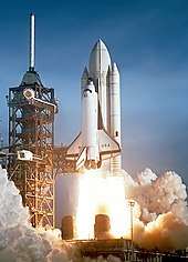
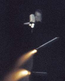
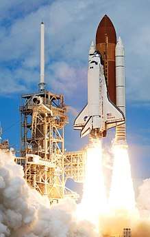 Discovery lifts off at the start of STS-120. | |
| Function | Crewed orbital launch and reentry |
|---|---|
| Manufacturer | United Space Alliance Thiokol/Alliant Techsystems (SRBs) Lockheed Martin/Martin Marietta (ET) Boeing/Rockwell (orbiter) |
| Country of origin | United States |
| Project cost | US$209 billion (2010)[1][2][3] |
| Cost per launch | US$450 million (2011)[4] to 1.5 billion (2011)[2][3][5][6] |
| Size | |
| Height | 56.1 m (184 ft 1 in) |
| Diameter | 8.7 m (28 ft 7 in) |
| Mass | 2,030,000 kg (4,470,000 lb) |
| Stages | 1.5 |
| Capacity | |
| Payload to LEO (204 km or 127 mi) | 27,500 kg (60,600 lb) |
| Payload to ISS (407 km or 253 mi) | 16,050 kg (35,380 lb) |
| Payload to polar orbit | 12,700 kg (28,000 lb) |
| Payload to GTO | 10,890 kg (24,010 lb) with Inertial Upper Stage[7] |
| Payload to GEO | 2,270 kg (5,000 lb) with Inertial Upper Stage[7] |
| Payload to Earth return | 14,400 kg (31,700 lb)[8] |
| Launch history | |
| Status | Retired |
| Launch sites | LC-39, Kennedy Space Center SLC-6, Vandenberg AFB (unused) |
| Total launches | 135 |
| Successes | 133[lower-alpha 1] |
| Failures | 2 Challenger (launch failure, 7 fatalities), Columbia (re-entry failure, 7 fatalities) |
| First flight | April 12, 1981 |
| Last flight | July 21, 2011 |
| Notable payloads | Tracking and data relay satellites Spacelab Hubble Space Telescope Galileo, Magellan, Ulysses Compton Gamma Ray Observatory Mir Docking Module Chandra X-ray Observatory ISS components |
| Boosters – Solid Rocket Boosters | |
| Engines | 2 solid |
| Thrust | 12,500 kN (2,800,000 lbf) each, sea level liftoff |
| Specific impulse | 242 seconds (2.37 km/s) |
| Burn time | 124 s |
| Fuel | Solid (ammonium perchlorate composite propellant) |
| First stage – Orbiter + external tank | |
| Engines | 3 RS-25 engines located on Orbiter |
| Thrust | 5,250 kN (1,180,000 lbf) total, sea level liftoff[9] |
| Specific impulse | 455 seconds (4.46 km/s) |
| Burn time | 480 s |
| Fuel | LH2 / LOX |
| Boosters | |
| No. boosters | 2 |
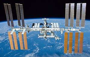
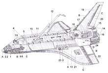
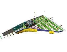
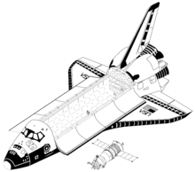
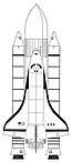
Shuttle components include the Orbiter Vehicle (OV) with three clustered Rocketdyne RS-25 main engines, a pair of recoverable solid rocket boosters (SRBs), and the expendable external tank (ET) containing liquid hydrogen and liquid oxygen. The Space Shuttle was launched vertically, like a conventional rocket, with the two SRBs operating in parallel with the OV's three main engines, which were fueled from the ET. The SRBs were jettisoned before the vehicle reached orbit, and the ET was jettisoned just before orbit insertion, which used the orbiter's two Orbital Maneuvering System (OMS) engines. At the conclusion of the mission, the orbiter fired its OMS to deorbit and reenter the atmosphere. The orbiter then glided as a spaceplane to a runway landing, usually to the Shuttle Landing Facility at KSC, Florida or Rogers Dry Lake in Edwards Air Force Base, California. After landing at Edwards, the orbiter was flown back to the KSC on the Shuttle Carrier Aircraft, a specially modified Boeing 747.
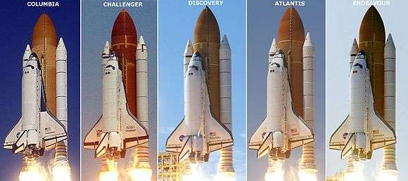
The first orbiter, Enterprise, was built in 1976, used in Approach and Landing Tests and has no orbital capability. Four fully operational orbiters were initially built: Columbia, Challenger, Discovery, and Atlantis. Of these, two were lost in mission accidents: Challenger in 1986 and Columbia in 2003, with a total of fourteen astronauts killed. A fifth operational (and sixth in total) orbiter, Endeavour, was built in 1991 to replace Challenger. The Space Shuttle was retired from service upon the conclusion of Atlantis's final flight on July 21, 2011. The U.S. has since relied on the Russian Soyuz spacecraft to transport astronauts to the International Space Station, pending the Commercial Crew Development and Space Launch System programs with flights to begin in the 2020s.
Design and development
Historical background

During the 1950s, the United States Air Force proposed using a reusable piloted glider to perform military operations such as reconnaissance, satellite attack, and employing air-to-ground weapons. In the late-1950s, the Air Force began developing the partially reusable X-20 Dyna-Soar. The Air Force collaborated with NASA on the Dyna-Soar, and began training six pilots in June 1961. The rising costs of development and the prioritization of Project Gemini led to the cancellation of the Dyna-Soar program in December 1963. In addition to the Dyna-Soar, the Air Force had conducted a study in 1957 to test the feasibility of reusable boosters. This became the basis for the aerospaceplane, a fully reusable spacecraft that was never developed beyond the initial design phase in 1962–1963.[12]:162–163
Beginning in the early 1950s, NASA and the Air Force collaborated on developing lifting bodies to test aircraft that primarily generated lift from their fuselages instead of wings, and tested the M2-F1, M2-F2, M2-F3, HL-10, X-24A, and the X-24B. The program tested aerodynamic characteristics that would later be applied to the Space Shuttle, including unpowered landing from a high altitude and speed.[13][14]:16–18
Design process
In September 1966, NASA and the Air Force released a joint study concluding that a new vehicle was required to satisfy their respective future demands, and that a partially reusable system would be the most cost-effective solution.[12]:164 The head of the NASA Office of Manned Space Flight, George Mueller, announced the plan for a reusable shuttle on August 10, 1968. NASA issued a request for proposal (RFP) for designs of the Integrated Launch and Re-entry Vehicle (ILRV), which would later become the Space Shuttle. Rather than award a contract based upon initial proposals, NASA announced a phased approach for the Space Shuttle contracting and development; Phase A was a request for studies completed by competing aerospace companies, Phase B was a competition between two contractors for a specific contract, Phase C involved designing the details of the spacecraft components, and Phase D was the production of the spacecraft.[15][14]:19–22
In December 1968, NASA created the Space Shuttle Task Group to determine the optimal design for a reusable spacecraft, and issued study contracts to General Dynamics, Lockheed, McDonnell Douglas, and North American Rockwell. In July 1969, the Space Shuttle Task Group issued a report that determined the Shuttle would support a space station, launch, service, and retrieve satellites, and support short-duration crewed missions. The report also created three classes of a future reusable shuttle: Class I would have a reusable orbiter mounted on expendable boosters, Class II would use multiple expendable rocket engines and a single propellant tank (stage-and-a-half), and Class III would have both a reusable orbiter and a reusable booster. In September 1969, the Space Task Group, under leadership of Vice President Spiro Agnew, issued a report calling for the development of a space shuttle to bring people and cargo to low Earth orbit (LEO), as well as a space tug for transfers between orbits and the Moon, and a reusable nuclear stage for deep space travel.[12]:163–166[10]
After the release of the Space Shuttle Task Group report, many aerospace engineers favored the Class III, fully reusable design because of perceived savings in hardware costs. Max Faget, a NASA engineer who had worked to design the Mercury capsule, patented a design for a two-stage fully recoverable system with a straight-winged orbiter mounted on a larger straight-winged booster.[16][17] The Air Force Flight Dynamics Laboratory argued that a straight-wing design would not be able to withstand the high thermal and aerodynamic stresses during reentry, and would not provide the required cross-range capability. Additionally, the Air Force required a larger payload capacity than Faget's design allowed. In January 1971, NASA and Air Force leadership decided that a reusable delta-wing orbiter mounted on an expendable propellant tank would be the optimal design for the Space Shuttle.[12]:166
After establishing the need for a reusable, heavy-lift spacecraft, NASA and the Air Force began determining the design requirements of their respective services. The Air Force expected to use the Space Shuttle to launch large satellites, and required it to be capable of lifting 29,000 kg (65,000 lb) to an eastward LEO or 18,000 kg (40,000 lb) into a polar orbit. The satellite designs also required that the Space Shuttle have a 4.6-by-18-meter (15 by 60 ft) payload bay. NASA evaluated the F-1 and J-2 engines from the Saturn rockets, and determined that they were insufficient for the requirements of the Space Shuttle; in July 1971, it issued a contract to Rocketdyne to begin development on the RS-25 engine.[12]:165–170
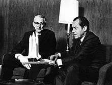
NASA reviewed 29 potential designs for the Space Shuttle, and determined that a design with two side boosters should be used, and the boosters should be reusable to reduce costs.[12]:167 NASA and the Air Force elected to use solid-propellant boosters because of the lower costs and the ease of refurbishing them for reuse after they landed in the ocean. In January 1972, President Richard Nixon approved the Shuttle, and NASA decided on its final design in March. That August, NASA awarded the contract to build the orbiter to North American Rockwell, the solid-rocket booster contract to Morton Thiokol, and the external tank contract to Martin Marietta.[12]:170–173
Development
On June 4, 1974, Rockwell began construction on the first orbiter, OV-101, which would later be named Enterprise. Enterprise was designed as a test vehicle, and did not include engines or heat shielding. Construction was completed on September 17, 1976, and Enterprise was moved to the Edwards Air Force Base to begin testing.[12]:173[18] Rockwell constructed the Main Propulsion Test Article (MPTA)-098, which was a structural truss mounted to the ET with three RS-25 engines attached. It was tested at the National Space Technology Laboratory (NSTL) to ensure that the engines could safely run through the launch profile.[19]:II-163 Rockwell conducted mechanical and thermal stress tests on Structural Test Article (STA)-099 to determine the effects of aerodynamic and thermal stresses during launch and reentry.[19]:I-415
The beginning of the development of the RS-25 Space Shuttle Main Engine was delayed for nine months while Pratt & Whitney challenged the contract that had been issued to Rocketdyne. The first engine was completed in March 1975, after issues with developing the first throttlable, reusable engine. During engine testing, the RS-25 experienced multiple nozzle failures, as well as broken turbine blades. Despite the problems during testing, NASA ordered the nine RS-25 engines needed for its three orbiters under construction in May 1978.[12]:174–175
NASA experienced significant delays in the development of the Space Shuttle's thermal protection system. Previous NASA spacecraft had used ablative heat shields, but those could not be reused. NASA chose to use ceramic tiles for thermal protection, as the shuttle could then be constructed of lightweight aluminum, and the tiles could be individually replaced as needed. Construction began on Columbia on March 27, 1975, and it was delivered to the KSC on March 25, 1979.[12]:175–177 At the time of its arrival at the KSC, Columbia still had 6,000 of its 30,000 tiles remaining to be installed. However, many of the tiles that had been originally installed had to be replaced, requiring two years of installation before Columbia could fly.[14]:46–48
On January 5, 1979, NASA commissioned a second orbiter. Later that month, Rockwell began converting STA-099 to OV-099, later named Challenger. On January 29, 1979, NASA ordered two additional orbiters, OV-103 and OV-104, which were named Discovery and Atlantis. Construction of OV-105, later named Endeavour, began in February 1982, but NASA decided to limit the Space Shuttle fleet to four orbiters in 1983. After the loss of Challenger, NASA resumed production of Endeavour in September 1987.[14]:52–53
Testing
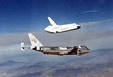
After it arrived at Edwards AFB, Enterprise underwent flight testing with the Shuttle Carrier Aircraft, a Boeing 747 that had been modified to carry the orbiter. In February 1977, Enterprise began the Approach and Landing Tests and underwent captive flights, where it remained attached to the Shuttle Carrier Aircraft for the duration of the flight. On August 12, 1977, Enterprise conducted its first glide test,[20] where it detached from the Shuttle Carrier Aircraft and landed at Edwards AFB.[12]:173–174 After four additional flights, Enterprise was moved to the Marshall Space Flight Center (MSFC) on March 13, 1978. Enterprise underwent shake tests in the Mated Vertical Ground Vibration Test, where it was attached to an external tank and solid rocket boosters, and underwent vibrations to simulate the stresses of launch. In April 1979, Enterprise was taken to the KSC, where it was attached to an external tank and solid rocket boosters, and moved to LC-39. Once installed at the launch pad, the Space Shuttle was used to verify the proper positioning of launch complex hardware. Enterprise was taken back to California in August 1979, and later served in the development of the SLC-6 at Vandenberg AFB in 1984.[14]:40–41
On November 26, 1980, Columbia was mated with its external tank and solid-rocket boosters, and was moved to LC-39 on December 29.[21] The first Space Shuttle mission, STS-1, would be the first time NASA performed a crewed first-flight of a spacecraft.[19]:III-24 On April 12, 1981, the Space Shuttle launched for the first time, and was piloted by John Young and Robert Crippen. During the two-day mission, Young and Crippen tested equipment on board the shuttle, and found several of the ceramic tiles had fallen off the top side of the Columbia.[22]:277-278 NASA coordinated with the Air Force to use satellites to image the underside of Columbia, and determined there was no damage.[22]:335-337 Columbia reentered the atmosphere and landed at Edwards AFB on April 14.[19]:III-24
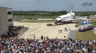
NASA conducted three additional test flights with Columbia in 1981 and 1982. On July 4, 1982, STS-4, flown by Ken Mattingly and Henry Hartsfield, landed on a concrete runway at Edwards AFB. President Ronald Reagan and his wife Nancy met the crew, and delivered a speech.[23] After STS-4, NASA declared the Space Shuttle operational.[12]:178–179
Description
The Space Shuttle was the first operational orbital spacecraft designed for reuse. Each Space Shuttle orbiter was designed for a projected lifespan of 100 launches or ten years of operational life, although this was later extended.[24] At launch, it consisted of the orbiter, which contained the crew and payload, the external tank (ET), and the two solid rocket boosters (SRBs).[25]:363
Responsibility for the Shuttle components was spread among multiple NASA field centers. The KSC was responsible for launch, landing and turnaround operations for equatorial orbits (the only orbit profile actually used in the program), the U.S. Air Force at the Vandenberg Air Force Base was responsible for launch, landing and turnaround operations for polar orbits (though this was never used), the Johnson Space Center (JSC) served as the central point for all Shuttle operations, the MSFC was responsible for the main engines, external tank, and solid rocket boosters, the John C. Stennis Space Center handled main engine testing, and the Goddard Space Flight Center managed the global tracking network.[26]
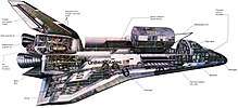
Orbiter
The orbiter had design elements and capabilities of both a rocket and an aircraft to allow it to launch vertically and then land as a glider.[25]:365 Its three-part fuselage provided support for the crew compartment, cargo bay, flight surfaces, and engines. The rear of the orbiter contained the Space Shuttle Main Engines (SSME), which provided thrust during launch, as well as the Orbital Maneuvering System (OMS), which allowed the orbiter to achieve, alter, and exit its orbit once in space. Its double-delta wings were 18-meter (60 ft) long, and were swept 81° at the inner leading edge and 45° at the outer leading edge. Each wing had an inboard and outboard elevon to provide flight control during reentry, along with a flap located between the wings, below the engines to control pitch. The orbiter's vertical stabilizer was swept backwards at 45°, and contained a rudder that could split to act as a speed brake.[25]:382–389 The vertical stabilizer also contained a two-part drag parachute system to slow the orbiter after landing. The orbiter used retractable landing gear with a nose landing gear and two main landing gear, each containing two tires. The main landing gear contained two brake assemblies each, and the nose landing gear contained an electro-hydraulic steering mechanism.[25]:408–411
Crew compartment
The crew compartment comprised three decks, and was the pressurized, habitable area on all Space Shuttle missions. The cockpit consisted of two seats for the commander and pilot, as well as an additional two to four seats for crew members. The mid-deck is located below the cockpit, and is where the galley and crew bunks were set up, as well as three or four crew member seats. The mid-deck contained the airlock, which could support two astronauts on an extravehicular activity (EVA), as well as access to pressurized research modules. An equipment bay was below the mid-deck, which stored environmental control and waste management systems.[14]:60–62[25]:365–369
On the first four Shuttle missions, astronauts wore modified U.S. Air Force high-altitude full-pressure suits, which included a full-pressure helmet during ascent and descent. From the fifth flight, STS-5, until the loss of Challenger, the crew wore one-piece light blue nomex flight suits and partial-pressure helmets. After the Challenger disaster, the crew members wore the Launch Entry Suit (LES), a partial-pressure version of the high-altitude pressure suits with a helmet. In 1994, the LES was replaced by the full-pressure Advanced Crew Escape Suit (ACES), which improved the safety of the astronauts in an emergency situation. Columbia originally had modified SR-71 zero-zero ejection seats installed for the ALT and first four missions, but these were disabled after STS-4 and removed after STS-9.[25]:370–371
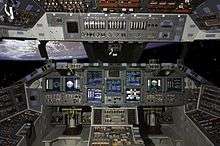
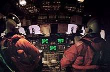
The flight deck was the top level of the crew compartment, and contained the flight controls for the orbiter. The commander sat in the front left seat, and the pilot sat in the front right seat, with two to four additional seats set up for additional crew members. The instrument panels contained over 2,100 displays and controls, and the commander and pilot were both equipped with a heads-up display (HUD) and a Rotational Hand Controller (RHC) to gimbal the engines during powered flight and fly the orbiter during unpowered flight. Both seats also had rudder controls, to allow rudder movement in flight and nose-wheel steering on the ground.[25]:369–372 The orbiter vehicles were originally installed with the Multifunction CRT Display System (MCDS) to display and control flight information. The MCDS displayed the flight information at the commander and pilot seats, as well as at the aft seating location, and also controlled the data on the HUD. In 1998, Atlantis was upgraded with the Multifunction Electronic Display System (MEDS), which was a glass cockpit upgrade to the flight instruments that replaced the eight MCDS display units with 11 multifunction colored digital screens. MEDS was flown for the first time in May 2000 on STS-98, and the other orbiter vehicles were upgraded to it. The aft section of the flight decked contained windows looking into the payload bay, as well as an RHC to control the Remote Manipulator System during cargo operations. Additionally, the aft flight deck had monitors for a closed-circuit television to view the cargo bay.[25]:372–376
The mid-deck was located underneath the flight deck. It contained the crew equipment storage, as well as the sleeping and hygiene stations for the crew. The mid-deck contained seats for three crewmembers (Columbia's mid-deck could seat four) during launch and landing procedures. The crew typically slept on the mid-deck, which also housed the galley, medical equipment, bathroom, and exercise equipment. The mid-deck contained modular lockers to store equipment that could be scaled depending on the needs of the crew, as well as permanently installed floor compartments. The mid-deck contained a port-side hatch that crew used for entry and exit while on Earth. Additionally, each orbiter was originally installed with an internal airlock in the mid-deck. The internal airlock was replaced with an external airlock in the payload bay on Discovery, Atlantis, and Endeavour to improve docking with Mir and the ISS, along with the Orbiter Docking System.[19]:II–26–33
Flight systems
The orbiter was equipped with an avionics system to provide information and control during atmospheric flight. Its avionics suite contained three microwave scanning beam landing systems, three gyroscopes, three TACANs, three accelerometers, two radar altimeters, two barometric altimeters, three attitude indicators, two Mach indicators, and two Mode C transponders. During reentry, the crew deployed two air data probes once they were travelling slower than Mach 5. The orbiter had three inertial measuring units (IMU) that it used for guidance and navigation during all phases of flight. The orbiter contains two star trackers to align the IMUs while in orbit. The star trackers are deployed while in orbit, and can automatically or manually align on a star. In 1991, NASA began upgrading the inertial measurement units with an inertial navigation system (INS), which provided more accurate location information. In 1993, NASA flew a GPS receiver for the first time aboard STS-51. In 1997, Honeywell began developing an integrated GPS/INS to replace the IMU, INS, and TACAN systems, which first flew on STS-118 in August 2007[25]:402–403
While in orbit, the crew primarily communicated using one of four S-band radios, which provided both voice and data communications. Two of the S band radios were phase modulation transceivers, and could transmit and receive information. The other two S band radios were frequency modulation transmitters, and were used to transmit data to NASA. As S band radios can operate only within their line of sight, NASA used the Tracking and Data Relay Satellite System and the Spacecraft Tracking and Data Acquisition Network ground stations to communicate with the orbiter throughout its orbit. Additionally, the orbiter deployed a high-bandwidth Ku-band radio out of the cargo bay, which could also utilized as a rendezvous radar. The orbiter was also equipped with two UHF radios for communications with air traffic control and astronauts conducting EVA.[25]:403–404
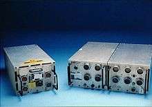
Although the orbiter could not be flown without a crew, its fly-by-wire control system was entirely reliant on its main computer, the Data Processing System (DPS). The DPS controlled the flight controls and thrusters on the orbiter vehicle, as well as the ET and SRBs during launch. The DPS consisted of five general purpose computers (GPC), two magnetic tape mass memory units (MMUs), and the associated sensors to monitors the Space Shuttle components.[25]:232–233 The original GPC used was the IBM AP-101B, which used a separate central processing unit (CPU) and inputer/output processor (IOP), and non-volatile solid-state memory. From 1991 to 1993, the orbiter vehicles were upgraded to the AP-101S, which improved the memory and processing capabilities, and reduced the volume and weight of the computers by combining the CPU and IOP into a single unit. Four of the GPCs were loaded with the Primary Avionics Software System (PASS), which was Space Shuttle-specific software that provided control through all phases of flight. During ascent, maneuvring, reentry, and landing, the four PASS GPCs functioned identically to produce quadruple redundancy, and would error check their results. In case of a software error that would cause erroneous reports from the four PASS GPCs, a fifth GPC ran the Backup Flight System, which used a different program and could control the Space Shuttle through ascent, orbit, and reentry, but could not support an entire mission. The five GPCs were separated in three separate bays within the mid-deck to provide redundancy in the event of a cooling fan failure. After achieving orbit, the crew would switch some of the GPCs functions from guidance, navigation, and control (GNC) to systems management (SM) and payload (PL) to support the operational mission.[25]:405–408 The Space Shuttle was not launched if its flight would run from December to January, as its flight software would have required the orbiter vehicle's computers to be reset at the year change. In 2007, NASA engineers devised a solution so Space Shuttle flights could cross the year-end boundary.[27]
Space Shuttle missions typically brought a portable general support computer (PGSC) that could integrate with the orbiter vehicle's computers and communication suite, as well as monitor scientific and payload data. Early missions brought the Grid Compass, one of the first laptop computers, as the PGSC, but later missions brought Apple and Intel laptops.[25]:408[28]
Payload bay

The payload bay comprised most of the orbiter vehicle's fuselage, and provided the cargo-carrying space for the Space Shuttle's payloads. It was 18-meter (60 ft) long and 4.6-meter (15 ft) wide, and could accommodate cylindrical payloads up to 15 feet (4.6 m) in diameter. Two payload bay doors hinged on either side of the bay, and provided a relatively airtight seal to protect payloads from heating during launch and reentry. Payloads were secured the in the payload bay to the attachment points on the longerons. The payload bay doors served an additional function as radiators for the orbiter vehicle's heat, and were opened upon reaching orbit for heat rejection.[14]:62–64
The orbiter could be used in conjunction with a variety of add-on components depending on the mission. This included orbital laboratories,[19]:II-304, 319 boosters for launching payloads farther into space,[19]:II-326 the Remote Manipulator System(RMS),[19]:II-40 and to extend the mission duration.[19]:II-86 To limit the fuel consumption while the orbiter was docked at the ISS, the Station-to-Shuttle Power Transfer System (SSPTS) was developed to convert and transfer station power to the orbiter.[19]:II-87-88 The SSPTS was first used on STS-118, and was installed on Discovery and Endeavour.[19]:III-366-368
Remote Manipulator System
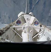
The RMS, also known as Canadarm, was a mechanical arm attached to the cargo bay. It could be used to grasp and manipulate payloads, as well as serve as a mobile platform for astronauts conducting an EVA. The RMS was built by the Canadian company Spar Aerospace, and was controlled by an astronaut inside the orbiter's flight deck using their windows and closed-circuit television. The RMS allowed for six degrees of freedom, and had six joints located at three points along the arm. The original RMS could deploy or retrieve payloads up to 29,000 kilograms (65,000 lb), which was later improved to 270,000 kilograms (586,000 lb).[25]:384–385
Spacelab
The Spacelab module was a European-funded pressurized laboratory that was carried within the payload bay and allowed for scientific research while in orbit. The Spacelab module contained two 2.7 m (9 ft) segments that were mounted in the aft end of the payload bay to maintain the center of gravity during flight. Astronauts entered the Spacelab module through a 2.7 m (8.72 ft) or 5.8 m (18.88 ft) tunnel that connected to the airlock. The Spacelab equipment was primarily stored in pallets, which provided storage for both experiments as well as computer and power equipment.[25]:434–435 Spacelab hardware was flown on 28 missions through 1999, and studied subjects including astronomy, microgravity, radar, and life sciences.Spacelab hardware also supported missions such as Hubble Space Telescope (HST) servicing and space station resupply. The Spacelab module was tested STS-2 and STS-3, and the first full mission was on STS-9.[29]
RS-25 engines
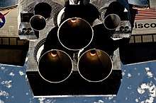
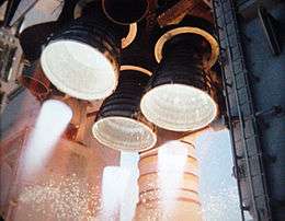
Three RS-25 engines, also known as the Space Shuttle Main Engines (SSME), were mounted on the orbiter's aft fuselage in a triangular pattern. The engine nozzles could gimbal ±10.5° in pitch, and ±8.5° in yaw during ascent to change the direction of their thrust to steer the Shuttle. The titanium alloy reusable engines were independent from the orbiter vehicle, and would be removed and replaced in between flights. The RS-25 is a staged-combustion cycle cryogenic engine that used liquid oxygen and hydrogen, and had a higher chamber pressure than any previous liquid rocket. The original main combustion chamber operated at a maximum pressure of 226.5 bars (3,285 psi). The engine nozzle is 287 centimeters (113 in) tall and has an interior diameter of 229 centimeters (90.3 in). The nozzle is cooled by 1,080 interior lines carrying liquid hydrogen, and is thermally protected by insulative and ablative material.[19]:II–177–183
The RS-25 engines had several improvements to enhance reliability and power. During the development program, Rocketdyne determined that the engine was capable of safe reliable operation at 104% of the originally specified thrust. To keep the engine thrust values consistent with previous documentation and software, NASA kept the original specified thrust as 100%, but had the RS-25 operate at higher thrust. RS-25 upgrade versions were denoted as Block I and Block II. 109% thrust level was achieved with the Block II engines in 2001, , which reduced the chamber pressue to 207.5 bars (3,010 psi), as it had a larger throat area. The normal maximum throttle was 104 percent, with 106% or 109% used for mission aborts.[14]:106–107
Orbital Maneuvering System
The Orbital Maneuvering System (OMS) consisted of two aft-mounted AJ10-190 engines and the associated fuel pods. The AJ10 engines used monomethylhydrazine (MMH) oxidized by dinitrogen tetroxide (N2O4). The pods carried a maximum of 2,140 kg (4,718 lb) of MMH and 3,526 kg (7,773 lb) of N2O4. The OMS engines were used after main engine cut-off (MECO) for orbital insertion. Throughout the flight, they were used for orbit changes, as well as the deorbit burn prior to reentry. Each OMS engine produced 27,080 N (6,087 lbf) of thrust, and the entire system could provide 305 m/s (1,000 ft/s) of velocity change.[19]:II–80
Thermal protection system
The orbiter was protected from heat during reentry by the thermal protection system (TPS), a thermal soaking protective layer around the orbiter. In contrast with previous US spacecraft, which had used ablative heat shields, the reusability of the orbiter required a multi-use heat shield.[14]:72–73 During reentry, the TPS experienced temperatures up to 1,600 °C (3,000 °F), but had to keep the orbiter vehicle's aluminum skin temperature below 180 °C (350 °F). The TPS primarily consisted of four types of tiles. The nose cone and leading edges of the wings experienced temperatures above 1,300 °C (2,300 °F), and were protected by reinforced carbon-carbon tiles (RCC). Thicker RCC tiles were developed and installed in 1998 to prevent damage from micrometeoroid and orbital debris, and were further improved after RCC damage caused of the Columbia disaster. Beginning with STS-114, the orbiter vehicles were equipped with the wing leading edge impact detection system to alert the crew to any potential damage.[19]:II–112–113 The entire underside of the orbiter vehicle, as well as the other hottest surfaces, were protected with high-temperature reusable surface insulation. Areas on the upper parts of the orbiter vehicle were coated in a white low-temperature reusable surface insulation, which provided protection for temperatures below 650 °C (1,200 °F). The payload bay doors and parts of the upper wing surfaces were coated in reusable felt surface insulation, as the temperature there remained below 370 °C (700 °F).[25]:395
External tank
The Space Shuttle external tank carried the propellant for the Space Shuttle Main Engines, and connected the orbiter vehicle with the solid rocket boosters. The external tank was 47 m (153.8 ft) tall and 8.4 m (27.6 ft) in diameter, and contained separate tanks for liquid oxygen (LOX) and liquid hydrogren (LH2). The LOX tank was housed in the nose of the external tank, and was 15 m (49.3 ft) tall. The LH2 comprised the bulk of the external tank, and was 29 m (96.7 ft) tall. The orbiter vehicle was attached to the external tank at two umbilical plates, which contained five propellant and two electrical umbilicals, and forward and aft structural attachments. The exterior of the external tank was covered in orange spray-on foam to allow it to survive the heat of ascent.[25]:421–422
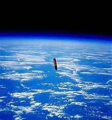
The external tank provided propellant to the Space Shuttle Main Engines from liftoff until main engine cutoff. The external tank separated from the orbiter vehicle 18 seconds after engine cutoff, and could be triggered automatically or manually. At the time of separation, the orbiter vehicle retracted its umbilical plates, and the umbilical cords were sealed to prevent excess propellant from venting into the orbiter vehicle. After the bolts attached at the structural attachments were sheared, the external tank separated from the orbiter vehicle. At the time of separation, gaseous oxygen was vented from the nose to cause the external tank to tumble, ensuring that it would break up upon reentry. The external tank was the only major component of the Space Shuttle system that was not reused, and it would travel along a ballistic trajectory into the Indian or Pacific Ocean.[25]:422
For the first two missions, STS-1 and STS-2, the external tank was covered in 270 kg (595 lb) of white Fire-Retardant Latex to provide further thermal insulation, but was determined to be unnecessary and removed, increasing the overall payload capacity..[25]:421 A light-weight tank (LWT) was first flown on STS-6, which reduced tank weight by 4,700 kg (10,300 lb). The LWT's weight was reduced by removing components from the LH2 tank and reducing the thickness of some skin panels.[25]:422 In 1998, a super light-weight external tank (SLWT) first flew on STS-91. The SLWT used the 2195 aluminum-lithium alloy, which was 40% stronger and 10% less dense than its predecessor, 2219 aluminum-lithium alloy. The SLWT weighed 3,400 kg (7,500 lb) less than the LWT, which allowed the Space Shuttle to deliver heavy elements to ISS's high inclination orbit.[25]:423-424
Solid Rocket Boosters
The Solid Rocket Boosters (SRB) provided 71.4% of the Space Shuttle's thrust during liftoff and ascent. They were the largest solid-propellant motors ever flown, and the only solid-propellant motors used on a crewed spacecraft.[30] Each SRB was 45 m (149.2 ft) tall and 3.7 m (12.2 ft) wide, weighed 68,000 kg (150,000 lb), and had a steel exterior approximately 13 mm (.5 in) thick. The SRB's subcomponents were the solid-propellant motor, nose cone, and rocket nozzle. The solid-propellant motor comprised the majority of the SRB's structure, and consisted of 11 steel sections. The nose cone housed the forward separation motors and the parachute systems that were used during recovery. The rocket nozzles could gimbal up to 8° to allow for in-flight adjustments.[25]:425–429
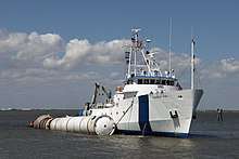
The rocket motors were each filled with a total 500,000 kg (1,106,640 lb) of solid rocket propellant, and joined together at the Vehicle Assembly Building (VAB) at the KSC.[25]:425–426 In addition to providing thrust during the first stage of launch, the SRBs provided structural support for the orbiter vehicle and ET, as they were the only system that was connected to the mobile launcher platform (MLP).[25]:427 At the time of launch, the SRBs were armed at T-5 minutes, and could only be electrically ignited once the RS-25 engines had ignited and were without issue.[25]:428 They each provided 12,500 kN (2,800,000 lbf) of thrust, which was later improved to 13,300 kN (3,000,000 lbf) beginning on STS-8.[25]:425 After expending their fuel, the SRBs were jettisoned approximately two minutes after launch at an altitude of approximately 46 km (150,000 ft). Following separation, they deployed drogue and main parachutes, landed in the ocean, and were recovered by the crews aboard the ships MV Freedom Star and MV Liberty Star.[25]:430 Once they were returned to Cape Canaveral, they were cleaned and disassembled. The rocket motor, igniter, and nozzle were then shipped to Thiokol to be refurbished and reused on subsequent flights.[14]:124
The SRBs underwent several redesigns throughout the program's lifetime. STS-6 and STS-7 used SRBs that were 2,300 kg (5,000 lb) lighter than the standard-weight cases due to walls that were 0.10 mm (.004 in) thinner, but were determined to be too thin. Subsequent flights until STS-26 used cases that were 0.076 mm (.003 in) thinner than the standard-weight cases, which saved 1,800 kg (4,000 lb). After the Challenger disaster as a result of a failed O-ring in cold temperature, the SRBs were redesigned to provide a constant seal regardless of the ambient temperature.[25]:425–426
Specifications
_and_Endeavour_(STS-400)_on_launch_pads.jpg)
Orbiter[25] (for Endeavour, OV-105)
- Length: 122.17 ft (37.237 m)
- Wingspan: 78.06 ft (23.79 m)
- Height: 56.58 ft (17.25 m)
- Empty weight: 172,000 lb (78,000 kg)[31]
- Gross liftoff weight (Orbiter only): 240,000 lb (110,000 kg)
- Maximum landing weight: 230,000 lb (100,000 kg)
- Payload to landing (return payload): 32,000 lb (14,400 kg)[8]
- Maximum payload: 55,250 lb (25,060 kg)
- Payload to LEO 204 kilometers (110 nmi) @ 28.5° inclination: 27,500 kilograms (60,600 lb)
- Payload to LEO (407 kilometers (220 nmi) @ 51.6° to ISS): 16,050 kilograms (35,380 lb)[32]
- Payload to GTO: 8,390 lb (3,806 kg)
- Payload to polar orbit: 28,000 lb (12,700 kg)
- Note launch payloads modified by external tank (ET) choice (ET, LWT, or SLWT)
- Payload bay dimensions (diameter by length): 15 by 59 ft (4.6 by 18 m)
- Operational altitude: 100 to 520 nmi (190 to 960 km; 120 to 600 mi)
- Speed: 7,743 m/s (27,870 km/h; 17,320 mph)
- Crossrange: 1,085 nmi (2,009 km; 1,249 mi)
- Main Stage (RS-25 with external tank)
- Engines: 3 Rocketdyne Block II RS-25s, each with a sea level thrust of 393,800 lbf (1,752 kN) at 104% power
- Thrust (at liftoff, sea level, 104% power, all 3 engines): 1,181,400 lbf (5,255 kN)
- Specific impulse: 455 seconds (4.46 km/s)
- Burn time: 480 s
- Propellant: liquid hydrogen/liquid oxygen
- Orbital Maneuvering System
- Engines: 2 AJ10 engines
- Thrust: 53.4 kN (12,000 lbf) combined total vacuum thrust
- Specific impulse: 316 seconds (3.10 km/s)
- Burn time: 150–250 s typical burn; 1250 s deorbit burn
- Propellant: MMH/N2O4
- Crew: varies
- The earliest Shuttle flights had the minimum crew of 2; later missions used a crew of 5. By the end of the program, typically 7 people would fly: (commander, pilot, several mission specialists, one of whom (MS-2) acted as the flight engineer starting with STS-9 in 1983). On two occasions, 8 astronauts have flown (STS-61-A, STS-71). In an emergency mission, 11 people could be accommodated (see STS-3xx).
External tank (for SLWT)
- Length: 46.9 m (153.8 ft)
- Diameter: 8.4 m (27.6 ft)
- Propellant volume: 2,025 m3 (534,900 U.S. gal)
- Empty weight: 26,535 kg (58,500 lb)
- Gross liftoff weight (for tank): 756,000 kg (1,670,000 lb)
Solid Rocket Boosters
- Length: 45.46 m (149 ft)[33]
- Diameter: 3.71 m (12.2 ft)[33]
- Empty weight (each): 68,000 kg (150,000 lb)[33]
- Gross liftoff weight (each): 571,000 kg (1,260,000 lb)[34]
- Thrust (at liftoff, sea level, each): 12,500 kN (2,800,000 lbf)
- Specific impulse: 242 seconds (2.37 km/s)
- Burn time: 124 s
System Stack
- Height: 56 m (180 ft)
- Gross liftoff weight: 2,000,000 kg (4,400,000 lb)
- Total liftoff thrust: 30,160 kN (6,780,000 lbf)
Mission profile
Launch preparation
The Space Shuttle was prepared for launch primarily in the VAB at the KSC. The SRBs were assembled and attached to the external tank on the MLP. The orbiter vehicle was prepared at the Orbiter Processing Facility and transferred to the VAB, where a crane was used to rotate it to the vertical orientation and mate it to the external tank. Once the entire stack was assembled, the MLP was carried for 5.6 kilometers (3.5 mi) to Launch Complex 39 by one of the crawler-transporters. After the Space Shuttle arrived at one of the two launchpads, it would connect to the Fixed and Rotation Service Structures, which provided servicing capabilities, payload insertion, and crew transportation. The crew was transported to the launch pad at T−2 hours 30 minutes, and the side hatch was closed 30 minutes later after the crew entered the orbiter vehicle.[14]:129–144[19]:III–8 LOX and LH2 were loaded into the external tank via umbilicals that attached to the orbiter vehicle, which began at T−5 hours 35 minutes. At T−3 hours 45 minutes, the LH2 fast-fill was complete, followed 15 minutes later by the LOX. Both tanks were slowly filled up until the launch as the oxygen and hydrogen evaporated.[19]:II–185
The launch commit criteria considered precipitation, temperatures, cloud cover, lightning forecast, wind, and humidity.[35] The Space Shuttle was not launched under conditions where it could have been struck by lightning, as its exhaust plume could have triggered lightning by providing a current path to ground after launch, which occurred on Apollo 12.[36]:239 The NASA Anvil Rule for a Shuttle launch stated that an anvil cloud could not appear within a distance of 10 nmi (19 km).[37] The Shuttle Launch Weather Officer monitored conditions until the final decision to scrub a launch was announced. Additionally, launch conditions required that the weather conditions were acceptable at one of the Transatlantic Abort Landing sites and the SRB recovery area.[35][38]
Launch
The mission crew and the Launch Control Center (LCC) personnel completed systems checks throughout the countdown. Two built-in holds at T−20 minutes and T−9 minutes provided scheduled breaks to address any issues and additional preparation.[19]:III–8 After the built-in hold at T−9 minutes, the countdown was automatically controlled by the Ground Launch Sequencer (GLS) at the LCC, which stopped the countdown if it sensed a critical problem with any of the Space Shuttle's onboard systems.[38] At T−3 minutes 45 seconds, the engines began conducting gimbal tests, which were concluded at T−2 minutes 15 seconds. The ground launch processing system handed off the control to the orbiter vehicle's GPCs at T−31 seconds. At T−16 seconds, the GPCs armed the SRBs, the sound suppression system (SPS) began to drench the MLP and SRB trenches with 1,100,000 L (300,000 U.S. gal) of water to protect the orbiter vehicle from damage by acoustical energy and rocket exhaust reflected from the flame trench and MLP during lift off.[39][40] At T−10 seconds, hydrogen igniters were activated under each engine bell to quell the stagnant gas inside the cones before ignition. Failure to burn these gases could trip the onboard sensors and create the possibility of an overpressure and explosion of the vehicle during the firing phase. The LH2 prevalves were opened at T−9.5 seconds in preparation for engine start.[19]:II–186
Beginning at T−6.6 seconds, the main engines were ignited sequentially at 120 millisecond intervals. All three RS-25 engines were required to reach 90% rated thrust by T−3 seconds, otherwise the GPCs would initiate an RSLS abort. If all three engines indicated nominal performance by T−3 seconds, they were commanded to gimbal to liftoff configuration and the command would be issued to arm the SRBs for ignition at T−0.[41] Between T−6.6 seconds and T−3 seconds, while the RS-25 engines were firing but the SRBs were still bolted to the pad, the offset thrust caused the Space Shuttle to pitch down 650 mm (25.5 in) measured at the tip of the external tank; the 3 second delay allowed the stack to return to nearly vertical before SRB ignition. At T−0 seconds, the eight frangible nuts holding the SRBs to the pad were detonated, the final umbilicals were disconnected, the SSMEs were commanded to 100% throttle, and the SRBs were ignited.[42][43] By T+0.23 seconds, the SRBs built up enough thrust for liftoff to commence, and reached maximum chamber pressure by T+0.6 seconds.[44][19]:II–186 At T−0, the JSC Mission Control Center assumed control of the flight from the LCC.[19]:III–9
At T+4 seconds, when the Space Shuttle reached an altitude of 22 meters (73 ft), the RS-25 engines were throttled up to 104.5%. At approximately T+7 seconds, the Space Shuttle rolled to a heads-down orientation at an altitude of 110 meters (350 ft), which reduced aerodynamic stress and provided an improved communication and navigation orientation. Approximately 20−30 seconds into ascent and an altitude of 2,700 meters (9,000 ft), the RS-25 engines were throttled down to 65−72% to reduce the maximum aerodynamic forces at Max Q.[19]:III–8-9 Additionally, the shape of the SRB propellant was designed to cause thrust to decrease at the time of Max Q.[25]:427 The GPCs could dynamically control the throttle of the RS-25 engines based upon the performance of the SRBs.[19]:II–187
At approximately T+123 seconds and an altitude of 46,000 meters (150,000 ft), pyrotechnic fasteners released the SRBs, which reached an apogee of 67,000 meters (220,000 ft) before parachuting into the Atlantic Ocean. The Space Shuttle continued its ascent using only the RS-25 engines. On earlier missions the Space Shuttle remained in the heads-down orientation to maintain communications with the tracking station in Bermuda, but later missions, beginning with STS-87, rolled to a heads up orientation at T+6 minutes for communication with the tracking and data relay satellite constellation. The RS-25 engines were throttled at T+7 minutes 30 seconds to limit vehicle acceleration to 3 g. At 6 seconds prior to main engine cutoff (MECO), which occurred at T+8 minutes 30 seconds, the RS-25 engines were throttled down to 67%. The GPCs controlled ET separation, and dumped the remaining LOX and LH2 to prevent outgassing while in orbit. The ET continued on a ballistic trajectory and broke up during reentry, with some small pieces landing in the Indian or Pacific Ocean.[19]:III–9–10
Early missions used two firings of the OMS to achieve orbit; the first firing raised the apogee while the second circularized the orbit. Missions after STS-38 used the RS-25 engines to achieve the optimal apogee, and used the OMS engines to circularize the orbit. The orbital altitude and inclination were mission dependent, and the Space Shuttle's orbits varied from 120 nmi (220 km) to 335 nmi (620 km).[19]:III–10
In orbit
The type of mission that the Space Shuttle was assigned to dictated the type of orbit that it entered. The initial design of the reusable Space Shuttle envisioned an increasingly cheap launch platform to deploy commercial and government satellites. Early missions routinely ferried satellites, which determined the type of orbit that the orbiter vehicle would enter. Following the Challenger disaster, many commercial payloads were moved to expendable commercial rockets, such as the Delta II.[19]:III–108, 123 While later missions still launched commercial payloads, Space Shuttle assignments were routinely directed towards scientific payloads, such as the Hubble Space Telescope,[19]:III–148 Spacelab,[25]:434–435 and the Galileo spacecraft.[19]:III–140 Beginning with STS-74, the orbiter vehicle conducted dockings with the Mir space station.[19]:III–224 In its final decade of operation, the Space Shuttle was used for the construction of the International Space Station.[19]:III–264 Most missions involved staying in orbit several days to two weeks, although longer missions were possible with the Extended Duration Orbiter pallet. The 17 day 15 hour STS-80 mission was the longest Space Shuttle mission duration.[19]:III–86, 238
Re-entry and landing

Approximately four hours prior to deorbit, the crew began preparing the orbiter vehicle for reentry by closing the payload doors, radiating excess heat, and retracting the Ku-band antenna. The orbiter vehicle maneuvered to an upside down, tail first orientation and began a 2-4 minute OMS burn approximately 20 minutes before it reenter the atmosphere. The orbiter vehicle reoriented itself to a nose-forward position with a 40° angle-of-attack, and the forward RCS jets were emptied of fuel and disabled prior to reentry. The orbiter vehicle's reentry was defined as starting at an altitude 400,000 ft (120 km), when it was traveling approximately Mach 25. The orbiter vehicle's reentry was controlled by the GPCs, which followed a preset angle-of-attack plan to prevent unsafe heating of the TPS. The GPCs also controlled the multiple aerobraking S-turns, using only the roll axis, to dissipate excess speed without changing the angle-of-attack.[19]:III–12[45]
The orbiter vehicle's aft RCS jets were disabled as it descended and its ailerons, elevators, and rudder became effective in the lower atmosphere. At an altitude of 150,000 ft (46 km), the orbiter vehicle opened its speed brake on the vertical stabilizer. At 8 minutes 44 seconds prior to landing, the crew deployed the air data probes, and began lowering the angle-of-attack to 36°. The orbiter's maximum glide ratio/lift-to-drag ratio varied considerably with speed, ranging from 1:1 at hypersonic speeds, 2:1 at supersonic speeds and reaching 4.5:1 at subsonic speeds during approach and landing. The orbiter vehicle flew to one of the two Heading Alignment Cones, located 48 kilometers (30 mi) away from each end of the runway's centerline, where it made its final turns to dissipate excess energy prior to its approach and landing. Once the orbiter vehicle was traveling subsonically, the crew took over manual control of the flight.[46][19]:III–12–13
The approach and landing phase began when the orbiter vehicle was at an altitude of 3,000 meters (10,000 ft) and traveling at 150 meters per second (300 kn). the orbiter vehicle followed either a -20° or -18° glideslope and descended at approximately 51 meters per second (167 ft/s). The speed brake was used to keep a continuous speed, and crew initiated a pre-flare maneuver to a -1.5° glideslope at an altitude of 610 meters (2,000 ft). The landing gear was deployed 10 seconds prior to touchdown, when the orbiter was at an altitude of 91 meters (300 ft) and traveling 150 meters per second (288 kn). A final flare maneuver reduced the orbiter vehicle's descent rate to 0.9 meters per second (3 ft/s), with touchdown occurring at 100–150 meters per second (195–295 kn), depending on the weight of the orbiter vehicle. After the landing gear touched down, the crew deployed a drag chute out of the vertical stabilizer, and began wheel braking when the orbiter vehicle was traveling slower than 72 meters per second (140 kn). After wheels stop, the crew deactivated the flight components and prepared to exit.[19]:III–13
Landing sites
The primary Space Shuttle landing site was the Shuttle Landing Facility at KSC. In the event of unfavorable landing conditions, the Shuttle could delay its landing or land at an alternate location. The primary alternate was Edwards AFB, which was used for 54 landings.[19]:III–18–20 STS-3 landed at the White Sands Space Harbor in New Mexico and required extensive post-processing after exposure to the gypsum-rich sand, some of which were found in Columbia debris after STS-107.[19]:III–28 Landings at alternate airfields required the Shuttle Carrier Aircraft to transport the orbiter back to Cape Canaveral.[19]:III–13
In addition to the pre-planned landing airfields, there were 85 agreed-upon emergency landing sites to be used in different abort scenarios, with 58 located in other countries. The landing locations were chosen based upon political relationships, favorable weather, a runway at least 7,500 feet (2,300 m) long, and TACAN or DME equipment. Additionally, as the orbiter vehicle only had UHF radios, international sites with only VHF radios would have been unable to communicate directly with the crew. Facilities on the east coast of the US were planned for East Coast Abort Landings, while several sites in Europe and Africa were planned in the event of a Transoceanic Abort Landing. The facilities were prepared with equipment and personnel in the event of an emergency shuttle landing, but were never used.[19]:III–19
Post-landing processing
After landing, the vehicle stayed on the runway for several hours for the orbiter to cool. Teams at the front and rear of the orbiter tested for presence of hydrogen, hydrazine, monomethylhydrazine, nitrogen tetroxide and ammonia (fuels and by-products of the reaction control system and the orbiter's three APUs). If hydrogen was detected, an emergency would be declared, the orbiter powered down and teams would evacuate the area. A convoy of 25 specially designed vehicles and 150 trained engineers and technicians approached the orbiter. Purge and vent lines were attached to remove toxic gases from fuel lines and the cargo bay about 45–60 minutes after landing. A flight surgeon boarded the orbiter for initial medical checks of the crew before disembarking. Once the crew left the orbiter, responsibility for the vehicle was handed from the JSC back to the KSC.[47] Once at the Shuttle Landing Facility, the orbiter was then towed 2 miles (3.2 km) along a tow-way and access roads normally used by tour buses and KSC employees to the Orbiter Processing Facility where it began a months-long preparation process for the next mission.[47]
Disasters
On January 28, 1986, STS-51-L disintegrated 73 seconds after launch due to the failure of the right SRB, killing all seven astronauts on board Challenger. The disaster was caused by low-temperature impairment of an O-ring, a mission-critical seal used between segments of the SRB casing. Failure of the O-ring allowed hot combustion gases to escape from between the booster sections and burn through the adjacent ET, leading to a sequence of events which caused the orbiter to disintegrate.[48] Repeated warnings from design engineers voicing concerns about the lack of evidence of the O-rings' safety when the temperature was below 53 °F (12 °C) had been ignored by NASA managers.[49]
On February 1, 2003, Columbia disintegrated during re-entry, killing all seven of the STS-107 crew, because of damage to the carbon-carbon leading edge of the wing caused during launch. Ground control engineers had made three separate requests for high-resolution images taken by the Department of Defense that would have provided an understanding of the extent of the damage, while NASA's chief TPS engineer requested that astronauts on board Columbia be allowed to leave the vehicle to inspect the damage. NASA managers intervened to stop the Department of Defense's assistance and refused the request for the spacewalk,[50] and thus the feasibility of scenarios for astronaut repair or rescue by Atlantis were not considered by NASA management at the time.[51]
Retirement
NASA retired the Space Shuttle in 2011, after 30 years of service. The Space Shuttle was originally conceived of and presented to the public as a vehicle which would, among other things, be used to build a United States space station in LEO in the early 1990s. The U.S. space station evolved into the International Space Station project, which suffered from long delays and design changes before it could be completed. As a result, the retirement of the Space Shuttle was delayed several times until 2011, serving at least 15 years longer than originally planned. Discovery was the first of NASA's three remaining operational Space Shuttles to be retired.[52]
The final Space Shuttle mission was originally scheduled for late 2010, but the program was later extended to July 2011 when Michael Suffredini of the ISS program said that one additional trip was needed in 2011 to deliver parts to the International Space Station.[53] STS-135 launched on July 8, 2011, and landed at the KSC on July 21, 2011, at 5:57 a.m. EDT (09:57 UTC).[54]
Orbiters on display
NASA announced it would transfer orbiters to education institutions or museums at the conclusion of the Space Shuttle program. Each museum or institution would be responsible for covering the US$28.8 million cost of preparing and transporting each vehicle for display. Twenty museums from across the country submitted proposals for receiving one of the retired orbiters.[55] On April 12, 2011, NASA announced selection of locations for the remaining Shuttle orbiters:[56][57]
- Atlantis is on display at the Kennedy Space Center Visitor Complex.[58]
- Discovery is on display at the Udvar-Hazy Center of the Smithsonian Institution's National Air and Space Museum in Chantilly, Virginia. Prior to its delivery in April 2012, it was flown atop a Shuttle Carrier Aircraft, escorted by a NASA T-38 Talon, over and around Washington, D.C., and landed at Washington Dulles International Airport.[59][60][61]
- Endeavour is on display at the California Science Center in Los Angeles, California. It arrived at Los Angeles International Airport on September 21, 2012 and was towed through the city on October 14, 2012.[62][63]
- Enterprise was on display at the National Air and Space Museum's Udvar-Hazy Center prior to the arrival of Discovery and was moved to New York City's Intrepid Sea-Air-Space Museum in 2012.[64][61][59]
- Independence, formerly known as Explorer, is a full-scale, high-fidelity replica of the Space Shuttle. It was built by Guard-Lee in Apopka, Florida, installed at the KSC Visitor Complex in 1993, and moved to Space Center Houston in 2012. It was built using schematics, blueprints and archival documents provided by NASA and by Space Shuttle contractors. While many of the features on the replica are simulated, some parts, including the landing gear's Michelin tires, have been used in the Space Shuttle program.[65] The model is on display, mounted on top of the original Shuttle Carrier Aircraft (NASA 905) outside of the Visitors' Center.[66]
- Pathfinder is a Space Shuttle test simulator made of steel and wood. It was constructed by NASA in 1977 as an unnamed test article, and was purchased in the early 1980s by the America-Japan Society, Inc. which had it refurbished, named it, and placed it on display in the Great Space Shuttle Exhibition in Tokyo. The mockup was later returned to the United States and placed on permanent display at the U.S. Space & Rocket Center in Huntsville, Alabama, in May 1988.[25]:215
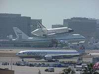 Endeavour at Los Angeles International Airport
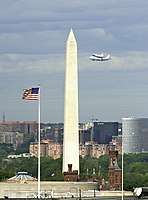 Discovery on Shuttle Carrier Aircraft prior to landing at Dulles International Airport
Distribution of hardware
One of the Crew Compartment Trainer (CCT) Flight and mid-deck training hardware is on display at the National Museum of the U.S. Air Force, while the other remains on display at the JSC. The Full Fuselage Trainer (FFT), which includes the payload bay and aft section but no wings, went to the Museum of Flight in Seattle, Washington. The Mission Simulation and Training Facility's Shuttle Mission Simulator Fixed Base Simulator went to the Adler Planetarium in Chicago, Illinois[67] but due to funding issues was later transferred to the Stafford Air & Space Museum in Weatherford, Oklahoma;[68] the Motion Base Simulator went to the Texas A&M Aerospace Engineering Department in College Station, Texas, where it remains in storage awaiting funding or other disposition;[69] and the Guidance and Navigation Simulator (GNS) went to the Wings of Dreams Aviation Museum in Starke, Florida.[70] One of the Single System Trainers (SSTs) used in Shuttle astronaut training went to the Virginia Air and Space Center in Hampton, Virginia, the other two remain on display at the JSC.[55] NASA also made TPS tiles available to schools and universities for less than US$25 each.[71] About 7,000 tiles were available on a first-come, first-served basis, limited to one per institution.[71]
In popular culture
The Space Shuttle, and fictitious variants, have been featured in numerous movies. The 1979 James Bond film Moonraker featured a Space Shuttle that was stolen while being transported by the SCA.[72] The 1986 film SpaceCamp portrayed Atlantis accidentally launching into space with a group of U.S. Space Camp participants as its crew.[73] The 2013 film Gravity features the fictional Space Shuttle Explorer during STS-157, whose crew are killed or left stranded after it is destroyed by a shower of high speed orbital debris.[74] The Space Shuttle has been featured as a Lego model, along with a large Lego Space Shuttle model that was constructed by visitors at the KSC.[75][76] The Space Shuttle also appears in a number of flight simulator and space flight simulator games such as Microsoft Space Simulator, Orbiter, and Space Shuttle Mission 2007.[77][78][79] The U.S. Postal Service has released several postage issues that depict the Space Shuttle. The first such stamps were issued in 1981, and are on display at the National Postal Museum.[80]
See also
- Buran – Soviet winged orbital vehicle
- Buran programme – Soviet research project on spaceplanes
- Shuttle-Derived Launch Vehicle
- Studied Space Shuttle variations and derivatives
Notes
- In this case, the number of successes is determined by the number of successful Space Shuttle missions.
- STS-1 and STS-2 were the only Space Shuttle missions that used a white fire-retardant coating on the external tank. Subsequent missions did not use the latex coating to reduce the mass, and the external tank appeared orange.[14]:48
- Endeavour served as the rescue orbiter vehicle on the final Hubble servicing mission, as the International Space Station would have been unreachable in the event of an emergency.
References
- Logsdon, John (July 6, 2011). "Was the Space Shuttle a Mistake?". MIT Technology Review. p. 2. Retrieved September 17, 2018.
- Pielke, Roger (2008). "The Rise and Fall of the Space Shuttle" (PDF). American Scientist. p. 32. Retrieved April 23, 2020.
- Bialik, Carl (July 9, 2011). "As Shuttle Sails Through Space, Costs Are Tough to Pin Down". The Wall Street Journal. Retrieved April 26, 2019.
- Bray, Nancy (August 4, 2017). "Space Shuttle and the International Space Station". NASA. Retrieved March 14, 2020.
- Wall, Mike (July 5, 2011). "NASA's Shuttle Program Cost $209 Billion—Was it Worth It?". Space.com. Retrieved April 26, 2019.
- Pielke Jr., Roger; Byerly, Radford (April 7, 2011). "Shuttle programme lifetime cost". Nature. 472 (7341): 38. Bibcode:2011Natur.472...38P. doi:10.1038/472038d. PMID 21475182.
- "Inertial Upper Stage". Retrieved July 21, 2012.
- Woodcock, Gordon R. (1986). Space stations and platforms. Orbit Book co. ISBN 9780894640018. Retrieved April 17, 2012.
The present limit on Shuttle landing payload is 14400 kg. (32000 lb). This value applies to payloads intended for landing.
- Kyle, Ed. "STS Data Sheet". spacelaunchreport.com. Retrieved May 4, 2018.
- Launius, Roger D. (1969). "Space Task Group Report, 1969". National Aeronautics and Space Administration. Retrieved March 22, 2020.
- Malik, Tarik (July 21, 2011). "NASA's Space Shuttle By the Numbers: 30 Years of a Spaceflight Icon". Space.com. Retrieved June 18, 2014.
- Williamson, Ray (1999). "Developing the Space Shuttle" (PDF). Exploring the Unknown: Selected Documents in the History of the U.S. Civil Space Program, Volume IV: Accessing Space. Washington, D.C.: National Aeronautics and Space Administration.
- Reed, R. Dale (January 1, 1997). "Wingless Flight: The Lifting Body Story" (PDF). NASA. Retrieved April 25, 2019.
- Baker, David (April 2011). NASA Space Shuttle: Owners' Workshop Manual. Somerset: Haynes Manual. ISBN 978-1-84425-866-6.
- Lindroos, Marcus (June 15, 2001). "Introduction to Future Launch Vehicle Plans [1963–2001]". Pmview.com. Retrieved April 25, 2019.
- Allen, Bob (August 7, 2017). "Maxime A. Faget". National Aeronautics and Space Administration. Retrieved April 24, 2019.
- United States of America 3,702,688, Maxime A. Faget, "Space Shuttle Vehicle and System", published November 14, 1972
- Howell, Elizabeth (October 9, 2012). "Enterprise: The Test Shuttle". Space.com. Retrieved April 24, 2019.
- Jenkins, Dennis R. (2016). Space Shuttle: Developing an Icon - 1972-2013. Specialty Press.
- "Shuttle's first glide a 'pushover'". Eugene Register-Guard. (Oregon). Associated Press. August 12, 1977. p. 1A.
- "Space Shuttle begins slow journey to launching pad". Eugene Register-Guard. (Oregon). Associated Press. December 29, 1980. p. 2A.
- White, Rowland (2016). Into the Black. New York: Touchstone. ISBN 978-1-5011-2362-7.
- "Shuttle test: 'Outstanding' was the word". Spokesman-Review. (Spokane, Washington). Associated Press. July 5, 1982. p. 1.
- Sivolella, David (2017). The Space Shuttle Program: Technologies and Accomplishments. Hemel Hempstead: Springer Praxis Books. doi:10.1007/978-3-319-54946-0. ISBN 978-3-319-54944-6.
- Jenkins, Dennis R. (2001). Space Shuttle: The History of the National Space Transportation System. Voyageur Press. ISBN 0-9633974-5-1.
- Dumoulin, Jim (August 31, 2000). "NASA Centers And Responsibilities". National Aeronautics and Space Administration. Retrieved March 22, 2020.
- Bergin, Chris (February 19, 2007). "NASA solves YERO problem for Shuttle". Archived from the original on April 18, 2008. Retrieved December 22, 2007.
- The Computer History Museum (2006). "Pioneering the Laptop:Engineering the GRiD Compass". The Computer History Museum. Archived from the original on December 4, 2007. Retrieved October 25, 2007.
- Dooling, Dave (March 15, 1999). "Spacelab joined diverse scientists and disciplines on 28 Shuttle missions". NASA. Retrieved April 23, 2020.
- Dunbar, Brian (March 5, 2006). "NASA—Solid Rocket Boosters". NASA. Archived from the original on April 6, 2013. Retrieved May 29, 2019.
- "John F. Kennedy Space Center—Space Shuttle Endeavour". Pao.ksc.nasa.gov. Archived from the original on May 21, 2011. Retrieved June 17, 2009.
- "Shuttle ISS". Encyclopedia Astronautica. Archived from the original on August 24, 2015.
- Jenkins, Dennis R. (2002). Space Shuttle: The History of the National Space Transportation System (Third ed.). Voyageur Press. ISBN 978-0-9633974-5-4.
- Space Shuttle Propulsion Systems, p. 153. NASA, June 26, 1990.
- Diller, George (May 20, 1999). "Space Shuttle weather launch commit criteria and KSC end of mission weather landing criteria". KSC Release No. 39-99. NASA Kennedy Space Center. Retrieved March 22, 2020.
- Chaikin, Andrew (2007). A Man on the Moon: The Voyages of the Apollo Astronauts. Penguin Group. ISBN 978-0-14-311235-8.
- Oblack, Rachelle (March 5, 2018). "The Anvil Rule: How NASA Keeps Its Shuttles Safe form Thunderstorms". Thoughtco.com. Retrieved September 17, 2018.
- "NASA's Launch Blog - Mission STS-121". National Aeronautics and Space Administration. July 1, 2006. Retrieved March 6, 2020.
- Ryba, Jeanne (November 23, 2007). "Sound Suppression System". National Aeronautics and Space Administration. Retrieved March 22, 2020.
- Grinter, Kay (August 28, 2000). "Sound Suppression Water System". National Aeronautics and Space Administration. Archived from the original on March 13, 2014. Retrieved April 9, 2020.
- Ryba, Jeanne (September 17, 2009). "Countdown 101". National Aeronautics and Space Administration. Retrieved March 22, 2020.
- Roy, Steve (November 2008). "Space Shuttle Solid Rocket Booster" (PDF). National Aeronautics and Space Administration. Retrieved March 22, 2020.
- Dumoulin, Jim (August 31, 2000). "Solid Rocket Boosters". National Aeronautics and Space Administration. Retrieved March 22, 2020.
- "Shuttle Crew Operations Manual" (PDF). nasa.gov. Retrieved May 4, 2018.
- NASA (1995). "Earth's Atmosphere". NASA. Archived from the original on October 13, 2007. Retrieved October 25, 2007.
- Chaffee, Norman (1985). "Space Shuttle Technical Conference" (PDF). NASA Conference Publication 2342. NASA. Retrieved March 14, 2020.
- "From Landing to Launch Orbiter Processing" (PDF). NASA Public Affairs Office. Archived from the original (PDF) on July 21, 2011. Retrieved June 30, 2011.
- "Report of the Presidential Commission on the Space Shuttle Challenger Accident, Chapter III: The Accident". NASA. June 6, 1986. Retrieved March 14, 2020.
- "Report of the Presidential Commission on the Space Shuttle Challenger Accident Chapter VI: An Accident Rooted in History". Presidential Commission on the Space Shuttle Challenger Accident. June 6, 1986. Retrieved March 16, 2020.
- "the Columbia Accident". Century of Flight. Retrieved May 28, 2019.
- "NASA Columbia Master Timeline". NASA. March 10, 2003. Retrieved May 28, 2019.
- "NASA—NASA's Shuttle and Rocket Launch Schedule". Nasa.gov. Retrieved July 17, 2009.
- Pike, John (May 13, 2010). "Space Shuttle may continue through next year—Roscosmos". Globalsecurity.org. Retrieved August 7, 2010.
- "Launch and Landing". NASA. Retrieved July 23, 2011.
- "Photo Gallery: How to display a retired space shuttle". collectSPACE. November 1, 2010. Retrieved July 11, 2011.
- Jason Townsend (April 12, 2011). "NASA Announces New Homes for Space Shuttle Orbiters After Retirement". NASA. Retrieved April 12, 2011.
- McGeehan, Patrick (April 12, 2011). "Space Shuttle to Land in Manhattan". The New York Times. Retrieved July 11, 2011.
- Pearlman, Robert (June 29, 2013). "Space Shuttle Atlantis Launches on Public Display in Florida". Space.com. Retrieved March 8, 2020.
- Vastag, Brian (April 18, 2012). "Space shuttle Discovery makes final flight over Washington D.C." The Washington Post. Retrieved March 8, 2020.
- Curie, Michael; Brown, Laura (April 9, 2012). "Space Shuttle Discovery to Fly Over Washington Metro Area April 17". National Aeronautics and Space Administration. Retrieved March 8, 2020.
- "Discovery's Arrival". National Air and Space Museum. April 19, 2012. Retrieved March 8, 2020.
- Lovett, Ian (October 12, 2012). "Space Shuttle Endeavour Rolls Through Los Angeles". The New York Times. Retrieved March 8, 2020.
- Taylor, Alan (October 13, 2012). "A Space Shuttle on the Streets of Los Angeles". The Atlantic. Retrieved March 8, 2020.
- Dunn, Marcia (January 15, 2010). "Recession Special: NASA Cuts Space Shuttle Price". ABC News. Archived from the original on January 18, 2010. Retrieved January 15, 2010.
- "Space shuttle replica sets sail for Houston". collectSPACE. May 24, 2012. Retrieved May 25, 2012.
- Moeller, Nathan (August 15, 2014). "Independence rises into history atop SCA at Space Center Houston". Spaceflight Insider. Archived from the original on September 19, 2014. Retrieved August 16, 2014.
- Mullen, W. "No shuttle for Adler, but museum will fly with simulator". Chicago Tribune. Retrieved March 16, 2019.
- Pearlman, Robert. "'Sooner State' shuttle: Stafford Museum to display NASA simulator in Oklahoma". collectSPACE. Retrieved March 16, 2019.
- Gilpin, Eva (September 8, 2014). "Funds shortage has NASA simulator collecting dust". The Battalion. Texas A&M University. Retrieved March 16, 2019.
- Winston, Hannah. "A piece of NASA history lands at Keystone Heights museum". gainesville.com. The Gainesville Sun. Retrieved March 16, 2019.
- "NASA offers space shuttle tiles to school and universities". Channel 13 News. December 1, 2010. Archived from the original on July 8, 2011. Retrieved July 11, 2011.
- "Moonraker". AFI Catalog of Feature Films. American Film Institute. 2019. Retrieved March 13, 2020.
- "Spacecamp". AFI Catalog of Feature Films. American Film Institute. 2019. Retrieved March 13, 2020.
- "Gravity". AFI Catalog of Feature Films. American Film Institute. 2019. Retrieved March 13, 2020.
- Cherie D. Abbey, Kevin Hillstrom, Biography today: profiles of people of interest to young readers, Volume 13, Issue 1 (2004), p. 55, Quote: "she went to the Kennedy Space Center in Florida, where she helped visitors build the world's largest Lego Space Shuttle"
- "Space Shuttle Explorer". Creator. Lego. 2020. Retrieved March 13, 2020.
- Buchanan, Lee (November 1994). "The Final Frontier". PC Gamer. Retrieved March 13, 2020.
- Schweiger, Martin (2010). "Orbiter Manual" (PDF). Retrieved March 13, 2020.
- "Space Shuttle Mission Simulation". Simsquared Ltd. 2007. Retrieved March 13, 2020.
- "18c Columbia Space Shuttle single". Space Achievement Issue. Arago. 2020. Retrieved March 13, 2020.
External links
| Wikimedia Commons has media related to Space Shuttle. |
- NSTS 1988 Reference manual
- How The Space Shuttle Works
- NASA Space Shuttle News Reference—1981
- Orbiter Vehicles
- The Space Shuttle Era: 1981–2011; interactive multimedia on the Space Shuttle orbiters
- NASA Human Spaceflight—Shuttle
- NASA Shuttle Gallery: Newer images, audio, and video of the Space Shuttle program
- High resolution spherical panoramas over, under, around and through Discovery, Atlantis and Endeavour
Space Shuttle program | ||
|---|---|---|
| ||
| Components |
|   |
| Orbiters |
| |
| Add-ons |
| |
| Sites |
| |
| Operations and training |
| |
| Testing |
| |
| Disasters |
| |
| Support |
| |
| Special |
| |
| Space suits |
| |
| Experiments |
| |
| Derivatives |
| |
| Replicas |
| |
| Related |
| |
Space Shuttle and Buran-class orbiters | |||||||
|---|---|---|---|---|---|---|---|
 |
|  | |||||
|||||||||||||||||||||||||||||||||||||||||||||||||||||||||||||||||||||||||||||||||||||||||||||||||||||||||||||||||||||||||||||||||||