Beat frequency oscillator
In a radio receiver, a beat frequency oscillator or BFO is a dedicated oscillator used to create an audio frequency signal from Morse code radiotelegraphy (CW) transmissions to make them audible. The signal from the BFO is mixed with the received signal to create a heterodyne or beat frequency which is heard as a tone in the speaker. BFOs are also used to demodulate single-sideband (SSB) signals, making them intelligible, by essentially restoring the carrier that was suppressed at the transmitter. BFOs are sometimes included in communications receivers designed for short wave listeners; they are almost always found in communication receivers for amateur radio, which often receive CW and SSB signals.[1]
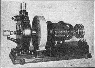
The beat frequency oscillator was invented in 1901 by Canadian engineer Reginald Fessenden. What he called the "heterodyne" receiver was the first application of the heterodyne principle.
Overview
In continuous wave (CW) radio transmission, also called radiotelegraphy or on-off keying and designated by the International Telecommunication Union as emission type A1A, information is transmitted by pulses of unmodulated radio carrier wave which spell out text messages in Morse code. The different length pulses of carrier, called "dots" and "dashes" or "dits" and "dahs", are produced by the operator switching the transmitter on and off rapidly using a switch called a telegraph key. This was the first type of radio transmission, and during the early 20th century was widely used for private person-to-person messages by amateurs and commercial telegram traffic. With the rise of other types of modulation its use has declined, and CW is now only used for personal hobbyist messages by radio amateurs and is otherwise obsolete.[2]
Since the pulses of carrier have no audio modulation, a CW signal received by an AM radio receiver simply sounds like silence.[3] In order to make the carrier pulses audible in the receiver, a beat frequency oscillator is used. The BFO is a radio frequency electronic oscillator that generates a constant sine wave at a frequency fBFO that is offset from the intermediate frequency fIF of the receiver. This signal is mixed with the IF before the receiver's second detector (demodulator). In the detector the two frequencies add and subtract, and a beat frequency (heterodyne) in the audio range results at the difference between them: faudio = |fIF - fBFO| which sounds like a tone in the receiver's speaker. During the pulses of carrier, the beat frequency is generated, while between the pulses there is no carrier so no tone is produced. Thus the BFO makes the "dots" and "dashes" of the Morse code signal audible, sounding like different length "beeps" in the speaker. A listener who knows Morse code can decode this signal to get the text message.
The first BFOs, used in early tuned radio frequency (TRF) receivers in the 1910s-1920s, beat with the carrier frequency of the station. Each time the radio was tuned to a different station frequency, the BFO frequency had to be changed also, so the BFO oscillator had to be tunable across the entire frequency band covered by the receiver.
Since in a superheterodyne receiver the different frequencies of the different stations are all translated to the same intermediate frequency (IF) by the mixer, modern BFOs which beat with the IF need only have a constant frequency. There may be a switch to turn off the BFO when it is not needed, when receiving other types of signals, such as AM or FM. There is also usually a knob on the front panel to adjust the frequency of the BFO, to change the tone over a small range to suit the operator's preference.
Example

A receiver is tuned to a Morse code signal, and the receiver's intermediate frequency (IF) is fIF = 45000 Hz. That means the dits and dahs have become pulses of a 45000 Hz signal, which is inaudible.
To make them audible, the frequency needs to be shifted into the audio range, for instance faudio = 1000 Hz. To achieve that, the desired BFO frequency is fBFO = 44000 or 46000 Hz.
When the signal at frequency fIF is mixed with the BFO frequency in the detector stage of the receiver, this creates two other frequencies or heterodynes: |fIF − fBFO|, and |fIF + fBFO|. The difference frequency, faudio = |fIF − fBFO| = 1000 Hz, is also known as the beat frequency.
The other, the sum frequency, (Fif + Fbfo) = 89000 or 91000 Hz, is unneeded. It can be removed by a lowpass filter, such as the radio's speaker, which cannot vibrate at such a high frequency.
fBFO = 44000 or 46000 Hz produces the desired 1000 Hz beat frequency and either could be used.
By varying the BFO frequency around 44000 (or 46000) Hz, the listener can vary the output audio frequency; this is useful to correct for small differences between the tuning of the transmitter and the receiver, particularly useful when tuning in single sideband (SSB) voice. The waveform produced by the BFO beats against the IF signal in the mixer stage of the receiver. Any drift of the local oscillator or the beat-frequency oscillator will affect the pitch of the received audio, so stable oscillators are used.[4]
For single sideband reception, the BFO frequency is adjusted above or below the receiver intermediate frequency, depending on which sideband is used.[1]
Other uses
Another form of beat-frequency oscillator is used as an adjustable audio frequency signal generator. The signal from a stable crystal-controlled oscillator is mixed with the signal from a tuneable oscillator; the difference in the audio range is amplified and sent as the output of the signal generator. By using crystal and adjustable frequencies higher than the audio frequency desired, a wide tuning range can be obtained for a small adjustment in the variable oscillator.[5] Although the beat-frequency oscillator can produce an output with low distortion, the two oscillators must be very stable to maintain a constant output frequency. [6]
References
- Larry Wolfgang, Charles Hutchinson (ed), The ARRL Handbook for Radio Amateurs Sixty Eighth Edition, ARRL, ISBN 978-0872591684-9, pages 12-29,12-30
- David Rutledge, The Electronics of Radio, Cambridge University Press, 1999 ISBN 0521646456 page 309
- Sometimes, when the carrier pulses are strong enough to block out the normal static atmospheric "hiss" in the receiver, CW signals could be heard without a BFO as "pulses" of silence. However this was not a reliable method of reception
- Paul Horowitz, Winfield Hill "The Art of Electronics 2nd Ed." Cambridge University Press 1989 ISBN 0-521-37095-7, page 898
- E. G. Lapham, An Improved Audio Frequency Generator RP367, Bureau of Standards Journal of Research Vol 7, United States National Bureau of Standards, 1932 page 691 ff
- Frank Spitzer, Barry Howarth, Principles of Modern Instrumentation, Holt, Rinehart and Winston, 1972, ISBN 0-03-080208-3, page 98
Further reading
- "Radiotelephone", NEETS, Module 17--Radio-Frequency Communication Principles. Integrated Publishing, Electrical Engineering Training Series.
- "Voice Modes", ARRL.