PMOS logic
P-type metal-oxide-semiconductor logic uses p-channel (+) metal-oxide-semiconductor field effect transistors (MOSFETs) to implement logic gates and other digital circuits. PMOS transistors operate by creating an inversion layer in an n-type transistor body. This inversion layer, called the p-channel, can conduct holes between p-type "source" and "drain" terminals.

The p-channel is created by applying voltage to the third terminal, called the gate. Like other MOSFETs, PMOS transistors have four modes of operation: cut-off (or subthreshold), triode, saturation (sometimes called active), and velocity saturation.
While PMOS logic is easy to design and manufacture (a MOSFET can be made to operate as a resistor, so the whole circuit can be made with PMOS FETs), it has several shortcomings as well. The worst problem is that there is a direct current (DC) through a PMOS logic gate when the PUN is active, that is, whenever the output is high, which leads to static power dissipation even when the circuit sits idle.
Also, PMOS circuits are slow to transition from high to low. When transitioning from low to high, the transistors provide low resistance, and the capacitive charge at the output accumulates very quickly (similar to charging a capacitor through a very low resistance). But the resistance between the output and the negative supply rail is much greater, so the high-to-low transition takes longer (similar to discharge of a capacitor through a high resistance). Using a resistor of lower value will speed up the process but also increases static power dissipation.
Additionally, the asymmetric input logic levels make PMOS circuits susceptible to noise.[1]
Most PMOS integrated circuits require a power supply of 17-24 volt DC.[2] The Intel 4004 PMOS microprocessor, however, uses PMOS logic with polysilicon rather than metal gates allowing a smaller voltage differential. For compatibility with TTL signals, the 4004 uses positive supply voltage VSS=+5V and negative supply voltage VDD = -10V.[3]
Though initially easier to manufacture,[4] PMOS logic was later supplanted by NMOS logic using n-channel field-effect transistors. NMOS is faster than PMOS. Modern integrated circuits are CMOS logic, which uses both p-channel and n-channel transistors.
Gates
The p-type MOSFETs are arranged in a so-called "pull-up network" (PUN) between the logic gate output and positive supply voltage, while a resistor is placed between the logic gate output and the negative supply voltage. The circuit is designed such that if the desired output is high, then the PUN will be active, creating a current path between the positive supply and the output.
PMOS gates have the same arrangement as NMOS gates if all the voltages are reversed.[4] Thus, for active-high logic, De Morgan's laws show that a PMOS NOR gate has the same structure as an NMOS NAND gate and vice versa.
 PMOS inverter with load resistor. |
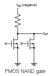 PMOS NAND gate with load resistor. |
 PMOS NOR gate with load resistor. |
History
After the invention of the MOSFET by Mohamed Atalla and Dawon Kahng at Bell Labs in 1959, they demonstrated MOSFET technology in 1960.[5] They fabricated both pMOS and nMOS devices with a 20 µm process. However, the nMOS devices were impractical, and only the pMOS type were practical working devices.[6] A more practical nMOS process was developed several years later.
The earliest microprocessors in the early 1970s were PMOS processors, which initially dominated the early microprocessor industry. By the late 1970s, NMOS microprocessors had overtaken PMOS processors.[7]
References
- "Microwave Engineering: Concepts and Fundamentals". 2014. p. 629. Retrieved 2016-04-10.
Also, the asymmetric input logic levels make PMOS circuits susceptible to noise.
- Fairchild (January 1983). "CMOS, the Ideal Logic Family" (PDF). p. 6. Archived from the original (PDF) on 2015-01-09. Retrieved 2015-07-03.
Most of the more popular P-MOS parts are specified with 17V to 24V power supplies while the maximum power supply voltage for CMOS is 15V.
- "Intel 4004 datasheet" (PDF) (published 2010-07-06). 1987. p. 7. Retrieved 2011-07-06.
- Microelectronic Device Data Handbook (PDF) (NPC 275-1 ed.). NASA / ARINC Research Corporation. August 1966. p. 2-51.
- "1960 - Metal Oxide Semiconductor (MOS) Transistor Demonstrated". The Silicon Engine. Computer History Museum.
- Lojek, Bo (2007). History of Semiconductor Engineering. Springer Science & Business Media. pp. 321-3. ISBN 9783540342588.
- Kuhn, Kelin (2018). "CMOS and Beyond CMOS: Scaling Challenges". High Mobility Materials for CMOS Applications. Woodhead Publishing. p. 1. ISBN 9780081020623.
Further reading
- Savard, John J. G. (2018) [2005]. "What Computers Are Made From". quadibloc. Archived from the original on 2018-07-02. Retrieved 2018-07-16.