J-pole antenna
The J-pole antenna, more properly known as the J antenna,[1] was first invented by Hans Beggerow in 1909 for use in Zeppelin airships.[2] Trailed behind the airship, it consisted of a single element, one half wavelength long radiator with a quarter wave parallel feedline tuning stub. This concept evolved to the J configuration by 1936[3] attaining the name J Antenna by 1943.[1] When the radiating half-wave section is mounted horizontally, at right-angles to the quarter-wave matching stub, the variation is typically called a "Zepp" antenna.[4]

Characteristics
The J-pole antenna is an end-fed omnidirectional half-wave antenna that is matched to the feedline by a quarter wave parallel transmission line stub[1] of Lecher system form.[2] Matching to the feed-line is achieved by sliding the connection of the feedline back and forth along the stub until an impedance match is obtained.[1] Being a half-wave antenna, it provides a small gain over a quarter-wave ground-plane antenna.[5]
Gain and radiation pattern
_vs._a_reference_dipole.svg.png)
Primarily a dipole, the J-pole antenna exhibits a mostly circular pattern in the H plane with an average free-space gain near 2.2 dBi (0.1 dBd).[6] Measurements and simulation confirm the quarter-wave stub modifies the circular H-plane pattern shape increasing the gain slightly on the side of the J stub element and reducing the gain slightly on the side opposite the J stub element.[6][7] At right angles to the J-stub, the gain is closer to the overall average: about 2.2 dBi (0.1 dBd).[6] The slight increase over a dipole's 2.15 dBi (0 dBd) gain represents the small contribution to the pattern made by the current imbalance on the matching section.[6] The pattern in the E plane reveals a slight elevation of the pattern in the direction of the J element while the pattern opposite the J element is mostly broadside.[7] The net effect of the perturbation caused by quarter-wave stub is an H-plane approximate gain from 1.5 to 2.6 dBi (-0.6 dBd to 0.5 dBd).[7]
Environment
Like all antennas, the J-pole is sensitive to electrically conductive objects in its induction fields[8] (aka reactive near-field region [9]) and should maintain sufficient separation to minimize these near field interactions as part of typical system installation considerations.[10] The quarter wave parallel transmission line stub has an external electromagnetic field with strength and size proportional to the spacing between the parallel conductors.[11] The parallel conductors must be kept free of moisture, snow, ice and should be kept away from other conductors including downspouts, metal window frames, flashing, etc. by a distance of two to three times the spacing between the parallel stub conductors.[4] The J-Pole is very sensitive to conductive support structures and will achieve best performance with no electrical bonding between antenna conductors and the mounting structure.[12][13]
Feed and mounting
Feed
The J-pole antenna and its variations may be fed with balanced line.[1] A coax feed line may be used if it includes a means to suppress feed-line RF currents.[12][15] The feed-point of the J-pole is somewhere between the closed low-impedance bottom and open high-impedance top of the J stub.[1][3] Between these two extremes a match to any impedance between the low to high impedance points is available.[1][3]
Mounting
The J-pole design functions well when fed with a balanced feed (via balun, transformer or choke) and no electrical connection exists between its conductors and surrounding supports.[12][13] Historical documentation of the J antenna suggests the lower end of the matching stub is at zero potential with respect to earth and can connect to a grounding wire or mast with no effect on the antenna's operation.[1] Later research confirms the tendency of the mast or grounding wire to draw current from the antenna potentially spoiling the antenna pattern.[16] A common approach extends the conductor below the bottom of the J-pole resulting in additional and undesirable RF currents flowing over every part of the mounting structure.[12] This modifies the far field antenna pattern[16] typically, but not always, raising the primary lobes above the horizon reducing antenna effectiveness for terrestrial service.[13] J-pole antennas with electrical connection to their supports often fare no better, and often much worse, than the simpler Monopole antenna.[12] A mast decoupling stub reduces mast currents.[16][17][18][19]
Variations

Slim Jim antenna
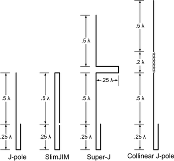
A variation of the J-pole is the Slim Jim antenna, also known as 2BCX Slim Jim,[20] that is related to the J-pole the way a folded dipole is related to a dipole.[21] The Slim Jim is one of many ways to form a J-Pole.[21] Introduced by Fred Judd (G2BCX) in 1978, the name was derived from its slim construction and the J type matching stub (J Integrated Matching).[20]
The Slim Jim variation of the J-pole antenna has characteristics and performance similar to a simple or folded Half-wave antenna and identical to the conventional J-pole construction.[21] Judd found the Slim Jim produces a lower takeoff angle and better electrical performance than a 5⁄8 wavelength ground plane antenna.[20] Slim Jim antennas made from ladder transmission line use the existing parallel conductor for the folded dipole element.[7] In the copper pipe variation, the Slim Jim uses more materials for no performance benefit.[7] Slim Jim antennas have no performance advantage over the conventional J-pole antenna.[7][21]
The approximate gain in the H-plane of the Slim Jim is from 1.5 to 2.6 dBi (-0.6 dBd to 0.5 dBd).[7]
Super-J antenna
The Super-J variation of the J-pole antenna adds another collinear half-wave radiator above the conventional J and connects the two with a phase stub to ensure both vertical half-wave sections radiate in current phase.[22] The phasing stub between the two half-wave sections is often of the Franklin style.[22][23][24]
The Super-J antenna compresses the vertical beamwidth and has more gain than the conventional J-pole design.[25] Both radiating sections have insufficient separation to realize the maximum benefits of collinear arrays, resulting in slightly less than the optimal 3 dB over a conventional J-pole or halfwave antenna.[25][26]
The approximate gain in the H-plane of the Super-J antenna is from 4.6 to 5.2 dBi (2.4 dBd to 3.1 dBd).[26]
Collinear J antenna
The collinear J antenna improves the Super-J by separating the two radiating half-wave sections to optimize gain using a phasing coil.[26] The resulting gain is closer to the optimum 3 dB over a conventional J-pole or halfwave antenna.[26]
The approximate gain in the H-plane of the Collinear J antenna is from 4.6 to 5.2 dBi (2.4 dBd to 3.1 dBd).[26]
E-plane gain patterns of the variations
The graph compares the E-plane gain of the above three variations to the conventional J antenna.
The conventional J antenna and SlimJIM variation are nearly identical in gain and pattern. The Super-J reveals the benefit of properly phasing and orienting a second radiator above the first. The Collinear J shows slightly higher performance over the Super-J.
Dual-band operation near 3rd harmonic
The basic J antenna resonates on the third harmonic of its lowest design frequency.[27] Operating a 3/2 wavelengths this way produces an antenna pattern unfavorable for terrestrial operation.[28]
To address the pattern change a variety of techniques exist to allegedly constrain a J antenna operating at or near the third harmonic so only one half-wave is active in the radiator above the stub. All involve the use of a high impedance choke at the first voltage loop.[28] These methods fall short of the goal as choking a high impedance point with a high impedance allows energy to pass the choke.[28][29]
References
- "Very-High-Frequency Antennas". Antennas and Antenna Systems (TM 11-314) (PDF). U.S. War Department. 30 November 1943. pp. 163–164. Retrieved 6 May 2016.
- Beggerow, Hans (1909). "Zeppelin Antenna" (PDF). Retrieved 28 January 2016.
- US patent 2124424, Laurance McConnell Leeds, "Antenna System", published 1938-07-19
- Hall, Gerald (1988). The ARRL Antenna Book (15th ed.). American Radio Relay League. p. 24.25. ISBN 0-87259-206-5.
- Huggins, John S. "1/4 Wave Monopole vs. 1/2 Wave J-Pole EZNEC Shootout". Retrieved 30 January 2012.
- Cebik, L.B. "Some J-Poles that I have known, Part 1: Why I finally got interested in J-Poles and some cautions in modeling them". Cebik.com. Archived from the original on April 22, 2014. Retrieved 1 October 2015.
- Huggins, John S. "Slim Jim vs. Traditional J-pole Antenna". Retrieved 28 August 2015.
- Griffith, B. Whitfield (1962). Radio-Electronic Transmission Fundamentals. New York, NY: McGraw Hill Book Company, Inc. pp. 322–323.
- Balani s, Constantine (1982). Antenna Theory. Harper & Row, Publishers, Inc. pp. 116–118. ISBN 0-06-040458-2.
- Collins, Brian (1984). "VHF and UHF Communication Antennas". In Johnson, Richard (ed.). Antenna Engineering Handbook (2nd ed.). New York, NY: McGraw-Hill. pp. 27.21–27.22. ISBN 0-07-032291-0.
- Griffith, B. Whitfield (1962). Radio-Electronic Transmission Fundamentals. New York, NY: McGraw Hill Book Company, Inc. pp. 243–244.
- Huggins, John S. "J-Pole Antenna – Should I ground it?". Retrieved 30 January 2012.
- Richardson, Dan (March 1998). "The J-Pole Revisited" (PDF). CQ Magazine: 34–41. Retrieved 30 January 2012.
- Fong, Edison (March 2007). "The DBJ-2: A Portable VHF-UHF Roll-Up J-pole Antenna for Public Service". QST. Newington, CT: ARRL, Inc.
- A folded-balun, sleeve balun, or common-mode choke will suppress feed-line RF currents. See: Straw, Dean (2007). "26 - Coupling the Line to the Antenna". The ARRL Antenna Book. Newington, CT: The ARRL, Inc. ISBN 0-87259-987-6.
- Huggins, John S. "Have your J-Pole and ground it too". Retrieved 4 March 2015.
- Huggins, John S. "Mast Mountable J-Pole Antenna". Retrieved 17 June 2015.
- Huggins, John. "Mast Mountable Antenna". USPTO via Google. US Government. Retrieved 22 July 2017.
- US patent D798847, "Antenna", issued 2017-10-03
- Judd, Fred (1978). "Slim Jim - 2 Metre Aerial". Practical Wireless - Out of Thin Air: 37–39. Retrieved 24 April 2014.
- Cebik, L. B. "What is a Slim Jim?". Cebik.com. Archived from the original on 24 April 2014. Retrieved 30 January 2012.
- Steve Cerwin (2007). "Mobile and Maritime Antennas - The Super-J Maritime Antenna". In Straw, Dean (ed.). ARRL Antenna Book (21st ed.). Newington, CT: The American Radio Relay League, Inc. pp. 16.23–16.26. ISBN 0-87259-987-6.
- Franklin, Charles (1924). "Franklin Antenna" (PDF). Retrieved 28 January 2016.
- Collins, Brian (1984). "VHF and UHF Communication Antennas - Base-Station Antennas". In Johnson, Richard; Henry Jasik (eds.). Antenna Engineering Handbook (2nd ed.). New York: McGraw-Hill. p. 27.14. ISBN 0-07-032291-0.
- Cebik, L.B. "Some J-Poles that I have known, Part 4: Some things we can and cannot do with a J-Pole". Cebik.com. Archived from the original on 22 April 2014. Retrieved 21 April 2014.
- Huggins, John S. "Improving the Super J-Pole Antenna". Retrieved 21 April 2014.
- Huggins, John. "Can a 2m J-Pole be used at 440?". Hamradio.me. Retrieved 12 June 2019.
- Huggins, John. "Antenna radiator decoupling stub flub?". Hamradio.me. Retrieved 12 June 2019.
- Huggins, John. "Where quarter-wave radiator decoupling stubs work ... and don't work". Hamradio.me. Retrieved 12 June 2019.