Phased array
In antenna theory, a phased array usually means an electronically scanned array, a computer-controlled array of antennas which creates a beam of radio waves that can be electronically steered to point in different directions without moving the antennas.[1][2][3][4][5][6][7][8] In an array antenna, the radio frequency current from the transmitter is fed to the individual antennas with the correct phase relationship so that the radio waves from the separate antennas add together to increase the radiation in a desired direction, while cancelling to suppress radiation in undesired directions. In a phased array, the power from the transmitter is fed to the antennas through devices called phase shifters, controlled by a computer system, which can alter the phase electronically, thus steering the beam of radio waves to a different direction. Since the array must consist of many small antennas (sometimes thousands) to achieve high gain, phased arrays are mainly practical at the high frequency end of the radio spectrum, in the UHF and microwave bands, in which the antenna elements are conveniently small.
Phased arrays were invented for use in military radar systems, to steer a beam of radio waves quickly across the sky to detect planes and missiles. These systems are now widely used and have spread to civilian applications. The phased array principle is also used in acoustics, and phased arrays of acoustic transducers are used in medical ultrasound imaging scanners (phased array ultrasonics), oil and gas prospecting (reflection seismology), and military sonar systems.
The term "phased array" is also used to a lesser extent for unsteered array antennas in which the phase of the feed power and thus the radiation pattern of the antenna array is fixed.[6][9] For example, AM broadcast radio antennas consisting of multiple mast radiators fed so as to create a specific radiation pattern are also called "phased arrays".
Types
Phased arrays take multiple forms. However, the four most common are the passive phased array (PESA), active electronically scanned array (AESA), hybrid beam forming phased array, and digital beam forming (DBF) array.[10]
A passive phased array or passive electronically scanned array (PESA) is a phased array in which the antenna elements are connected to a single transmitter and/or receiver, as shown in the animation at top. PESAs are the most common type of phased array. Generally speaking, a PESA uses one receiver/exciter for the entire array.
An active phased array or active electronically scanned array (AESA) is a phased array in which each antenna element has an analog transmitter/receiver (T/R) module[11] which creates the phase shifting required to electronically steer the antenna beam. Active arrays are a more advanced, second-generation phased-array technology which are used in military applications; unlike PESAs they can radiate several beams of radio waves at multiple frequencies in different directions simultaneously. However, the number of simultaneous beams is limited by practical reasons of electronic packaging of the beam former(s) to approximately three simultaneous beams for an AESA. Each beam former has a receiver/exciter connected to it.
A hybrid beam forming phased array can be thought of as a combination of an AESA and a digital beam forming phased array. It uses subarrays that are active phased arrays (for instance, a subarray may be 64, 128 or 256 elements and the number of elements depends upon system requirements). The subarrays are combined together to form the full array. Each subarray has its own digital receiver/exciter. This approach allows clusters of simultaneous beams to be created.
A digital beam forming (DBF) phased array has a digital receiver/exciter at each element in the array. The signal at each element is digitized by the receiver/exciter. This means that antenna beams can be formed digitally in a field programmable gate array (FPGA) or the array computer. This approach allows for multiple simultaneous antenna beams to be formed.
One possible physical implementation of a phased array is called a conformal antenna.[12] It is a phased array in which the individual antennas, instead of being arranged in a flat plane, are mounted on a curved surface. The phase shifters compensate for the different path lengths of the waves due to the antenna elements' varying position on the surface, allowing the array to radiate a plane wave. Conformal antennas are used in aircraft and missiles, to integrate the antenna into the curving surface of the aircraft to reduce aerodynamic drag.
History

Phased array transmission was originally shown in 1905 by Nobel laureate Karl Ferdinand Braun who demonstrated enhanced transmission of radio waves in one direction.[13][14] During World War II, Nobel laureate Luis Alvarez used phased array transmission in a rapidly steerable radar system for "ground-controlled approach", a system to aid in the landing of aircraft. At the same time, the GEMA in Germany built the Mammut 1.[15] It was later adapted for radio astronomy leading to Nobel Prizes for Physics for Antony Hewish and Martin Ryle after several large phased arrays were developed at the University of Cambridge. This design is also used for radar, and is generalized in interferometric radio antennas.
In 2004, Caltech researchers demonstrated the first integrated silicon-based phased array receiver at 24 GHz with 8 elements.[16] This was followed by their demonstration of a CMOS 24 GHz phased array transmitter in 2005[17] and a fully integrated 77 GHz phased array transceiver with integrated antennas in 2006[18][19] by the Caltech team. In 2007, DARPA researchers announced a 16 element phased array radar antenna which was also integrated with all the necessary circuits on a single silicon chip and operated at 30–50 GHz.[20]
The relative amplitudes of—and constructive and destructive interference effects among—the signals radiated by the individual antennas determine the effective radiation pattern of the array. A phased array may be used to point a fixed radiation pattern, or to scan rapidly in azimuth or elevation. Simultaneous electrical scanning in both azimuth and elevation was first demonstrated in a phased array antenna at Hughes Aircraft Company, California in 1957.[21]
Applications
Broadcasting
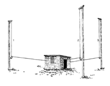
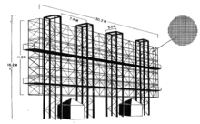
In broadcast engineering, phased arrays are used by many AM broadcast radio stations to enhance signal strength and therefore coverage in the city of license, while minimizing interference to other areas. Due to the differences between daytime and nighttime ionospheric propagation at mediumwave frequencies, it is common for AM broadcast stations to change between day (groundwave) and night (skywave) radiation patterns by switching the phase and power levels supplied to the individual antenna elements (mast radiators) daily at sunrise and sunset. For shortwave broadcasts many stations use arrays of horizontal dipoles. A common arrangement uses 16 dipoles in a 4×4 array. Usually this is in front of a wire grid reflector. The phasing is often switchable to allow Beam steering in azimuth and sometimes elevation.
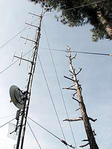
More modest phased array longwire antenna systems may be employed by private radio enthusiasts to receive longwave, mediumwave (AM) and shortwave radio broadcasts from great distances.
On VHF, phased arrays are used extensively for FM broadcasting. These greatly increase the antenna gain, magnifying the emitted RF energy toward the horizon, which in turn greatly increases a station's broadcast range. In these situations, the distance to each element from the transmitter is identical, or is one (or other integer) wavelength apart. Phasing the array such that the lower elements are slightly delayed (by making the distance to them longer) causes a downward beam tilt, which is very useful if the antenna is quite high on a radio tower.
Other phasing adjustments can increase the downward radiation in the far field without tilting the main lobe, creating null fill to compensate for extremely high mountaintop locations, or decrease it in the near field, to prevent excessive exposure to those workers or even nearby homeowners on the ground. The latter effect is also achieved by half-wave spacing – inserting additional elements halfway between existing elements with full-wave spacing. This phasing achieves roughly the same horizontal gain as the full-wave spacing; that is, a five-element full-wave-spaced array equals a nine- or ten-element half-wave-spaced array.
Radar
Phased array radar systems are also used by warships of many navies. Because of the rapidity with which the beam can be steered, phased array radars allow a warship to use one radar system for surface detection and tracking (finding ships), air detection and tracking (finding aircraft and missiles) and missile uplink capabilities. Before using these systems, each surface-to-air missile in flight required a dedicated fire-control radar, which meant that radar-guided weapons could only engage a small number of simultaneous targets. Phased array systems can be used to control missiles during the mid-course phase of the missile's flight. During the terminal portion of the flight, continuous-wave fire control directors provide the final guidance to the target. Because the antenna pattern is electronically steered, phased array systems can direct radar beams fast enough to maintain a fire control quality track on many targets simultaneously while also controlling several in-flight missiles.
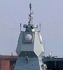
The AN/SPY-1 phased array radar, part of the Aegis Combat System deployed on modern U.S. cruisers and destroyers, "is able to perform search, track and missile guidance functions simultaneously with a capability of over 100 targets."[22] Likewise, the Thales Herakles phased array multi-function radar used in service with France and Singapore has a track capacity of 200 targets and is able to achieve automatic target detection, confirmation and track initiation in a single scan, while simultaneously providing mid-course guidance updates to the MBDA Aster missiles launched from the ship.[23] The German Navy and the Royal Dutch Navy have developed the Active Phased Array Radar System (APAR). The MIM-104 Patriot and other ground-based antiaircraft systems use phased array radar for similar benefits.
Phased arrays are used in naval sonar, in active (transmit and receive) and passive (receive only) and hull-mounted and towed array sonar.
Space probe communication
The MESSENGER spacecraft was a space probe mission to the planet Mercury (2011–2015[24]). This was the first deep-space mission to use a phased-array antenna for communications. The radiating elements are circularly-polarized, slotted waveguides. The antenna, which uses the X band, used 26 radiative elements and can gracefully degrade.[25]
Weather research usage

The National Severe Storms Laboratory has been using a SPY-1A phased array antenna, provided by the US Navy, for weather research at its Norman, Oklahoma facility since April 23, 2003. It is hoped that research will lead to a better understanding of thunderstorms and tornadoes, eventually leading to increased warning times and enhanced prediction of tornadoes. Current project participants include the National Severe Storms Laboratory and National Weather Service Radar Operations Center, Lockheed Martin, United States Navy, University of Oklahoma School of Meteorology, School of Electrical and Computer Engineering, and Atmospheric Radar Research Center, Oklahoma State Regents for Higher Education, the Federal Aviation Administration, and Basic Commerce and Industries. The project includes research and development, future technology transfer and potential deployment of the system throughout the United States. It is expected to take 10 to 15 years to complete and initial construction was approximately $25 million.[26] A team from Japan's RIKEN Advanced Institute for Computational Science (AICS) has begun experimental work on using phased-array radar with a new algorithm for instant weather forecasts.[27]
Optics
Within the visible or infrared spectrum of electromagnetic waves it is possible to construct optical phased arrays. They are used in wavelength multiplexers and filters for telecommunication purposes,[28] laser beam steering, and holography. Synthetic array heterodyne detection is an efficient method for multiplexing an entire phased array onto a single element photodetector. The dynamic beam forming in an optical phased array transmitter can be used to electronically raster or vector scan images without using lenses or mechanically moving parts in a lensless projector.[29] Optical phased array receivers have been demonstrated to be able to act as lensless cameras by selectively looking at different directions.[30][31]
Satellite broadband internet transceivers
Starlink is a low Earth orbit satellite constellation that is under construction as of 2020. It is designed to provide broadband internet connectivity to consumers; the user terminals of the system will use phased array antennas.[32]
Radio-frequency identification (RFID)
By 2014, phased array antennas were integrated into RFID systems to increase the area of coverage of a single system by 100% to 76,200 m2 (820,000 sq ft) while still using traditional passive UHF tags.[33]
Human-machine interfaces (HMI)
A phased array of acoustic transducers, denominated airborne ultrasound tactile display (AUTD), was developed in 2008 at the University of Tokyo's Shinoda Lab to induce tactile feedback.[34] This system was demonstrated to enable a user to interactively manipulate virtual holographic objects.[35]
Mathematical perspective and formulas
Mathematically a phased array is an example of N-slit diffraction, in which the radiation field at the receiving point is the result of the coherent addition of N point sources in a line. Since each individual antenna acts as a slit, emitting radio waves, their diffraction pattern can be calculated by adding the phase shift φ to the fringing term.
We will begin from the N-slit diffraction pattern derived on the diffraction formalism page, with slits of equal size and spacing .


Now, adding a φ term to the fringe effect in the second term yields:


Taking the square of the wave function gives us the intensity of the wave.

Now space the emitters a distance apart. This distance is chosen for simplicity of calculation but can be adjusted as any scalar fraction of the wavelength.


As sine achieves its maximum at , we set the numerator of the second term = 1.


Thus as N gets large, the term will be dominated by the term. As sine can oscillate between −1 and 1, we can see that setting will send the maximum energy on an angle given by


Additionally, we can see that if we wish to adjust the angle at which the maximum energy is emitted, we need only to adjust the phase shift φ between successive antennas. Indeed, the phase shift corresponds to the negative angle of maximum signal.
A similar calculation will show that the denominator is minimized by the same factor.
Different types of phased arrays
There are two main types of beamformers. These are time domain beamformers and frequency domain beamformers.
A graduated attenuation window is sometimes applied across the face of the array to improve side-lobe suppression performance, in addition to the phase shift.
Time domain beamformer works by introducing time delays. The basic operation is called "delay and sum". It delays the incoming signal from each array element by a certain amount of time, and then adds them together. A Butler matrix allows several beams to be formed simultaneously, or one beam to be scanned through an arc. The most common kind of time domain beam former is serpentine waveguide. Active phased array designs use individual delay lines that are switched on and off. Yttrium iron garnet phase shifters vary the phase delay using the strength of a magnetic field.
There are two different types of frequency domain beamformers.
The first type separates the different frequency components that are present in the received signal into multiple frequency bins (using either a Discrete Fourier transform (DFT) or a filterbank). When different delay and sum beamformers are applied to each frequency bin, the result is that the main lobe simultaneously points in multiple different directions at each of the different frequencies. This can be an advantage for communication links, and is used with the SPS-48 radar.
The other type of frequency domain beamformer makes use of Spatial Frequency. Discrete samples are taken from each of the individual array elements. The samples are processed using a DFT. The DFT introduces multiple different discrete phase shifts during processing. The outputs of the DFT are individual channels that correspond with evenly spaced beams formed simultaneously. A 1-dimensional DFT produces a fan of different beams. A 2-dimensional DFT produces beams with a pineapple configuration.
These techniques are used to create two kinds of phased array.
- Dynamic – an array of variable phase shifters are used to move the beam
- Fixed – the beam position is stationary with respect to the array face and the whole antenna is moved
There are two further sub-categories that modify the kind of dynamic array or fixed array.
- Active – amplifiers or processors are in each phase shifter element
- Passive – large central amplifier with attenuating phase shifters
Dynamic phased array
Each array element incorporates an adjustable phase shifter that are collectively used to move the beam with respect to the array face.
Dynamic phased array require no physical movement to aim the beam. The beam is moved electronically. This can produce antenna motion fast enough to use a small pencil-beam to simultaneously track multiple targets while searching for new targets using just one radar set (track while search).
As an example, an antenna with a 2 degree beam with a pulse rate of 1 kHz will require approximately 8 seconds to cover an entire hemisphere consisting of 8,000 pointing positions. This configuration provides 12 opportunities to detect a 1,000 m/s (2,200 mph; 3,600 km/h) vehicle over a range of 100 km (62 mi), which is suitable for military applications.
The position of mechanically steered antennas can be predicted, which can be used to create electronic countermeasures that interfere with radar operation. The flexibility resulting from phased array operation allows beams to be aimed at random locations, which eliminates this vulnerability. This is also desirable for military applications.
Fixed phased array
Fixed phased array antennas are typically used to create an antenna with a more desirable form factor than the conventional parabolic reflector or cassegrain reflector. Fixed phased arrays incorporate fixed phase shifters. For example, most commercial FM Radio and TV antenna towers use a collinear antenna array, which is a fixed phased array of dipole elements.
In radar applications, this kind of phased array is physically moved during the track and scan process. There are two configurations.
- Multiple frequencies with a delay-line
- Multiple adjacent beams
The SPS-48 radar uses multiple transmit frequencies with a serpentine delay line along the left side of the array to produce vertical fan of stacked beams. Each frequency experiences a different phase shift as it propagates down the serpentine delay line, which forms different beams. A filter bank is used to split apart the individual receive beams. The antenna is mechanically rotated.
Semi-active radar homing uses monopulse radar that relies on a fixed phased array to produce multiple adjacent beams that measure angle errors. This form factor is suitable for gimbal mounting in missile seekers.
Active phased array
Active electronically-scanned arrays (AESA) elements incorporate transmit amplification with phase shift in each antenna element (or group of elements). Each element also includes receive pre-amplification. The phase shifter setting is the same for transmit and receive.[36]
Active phased arrays do not require phase reset after the end of the transmit pulse, which is compatible with Doppler radar and pulse-Doppler radar.
Passive phased array
Passive phased arrays typically use large amplifiers that produce all of the microwave transmit signal for the antenna. Phase shifters typically consist of waveguide elements controlled by magnetic field, voltage gradient, or equivalent technology.[37][38]
The phase shift process used with passive phased arrays typically puts the receive beam and transmit beam into diagonally opposite quadrants. The sign of the phase shift must be inverted after the transmit pulse is finished and before the receive period begins to place the receive beam into the same location as the transmit beam. That requires a phase impulse that degrades sub-clutter visibility performance on Doppler radar and Pulse-Doppler radar. As an example, Yttrium iron garnet phase shifters must be changed after transmit pulse quench and before receiver processing starts to align transmit and receive beams. That impulse introduces FM noise that degrades clutter performance.
Passive phased array design is used in the AEGIS Combat System.[39] for direction-of-arrival estimation.
See also
- Active electronically scanned array
- Antenna array
- Aperture synthesis
- Beamforming
- Interferometric synthetic-aperture radar
- Inverse synthetic-aperture radar
- Multi-user MIMO
- Optical heterodyne detection
- Phased array ultrasonics
- Phased-array optics
- Radar MASINT
- Side-scan sonar
- Single-frequency network
- Smart antenna
- Synthetic-aperture radar
- Synthetic aperture sonar
- Synthetically thinned aperture radar
- Thinned-array curse
- Wave field synthesis
- History of smart antennas
- Reconfigurable antenna
References
- Milligan, Thomas A. (2005). Modern Antenna Design, 2nd Ed. John Wiley & Sons. ISBN 0471720607.
- Balanis, Constantine A. (2015). Antenna Theory: Analysis and Design, 4th Ed. John Wiley & Sons. pp. 302–303. ISBN 1119178983.
- Stutzman, Warren L.; Thiele, Gary A. (2012). Antenna Theory and Design. John Wiley & Sons. p. 315. ISBN 0470576642.
- Lida, Takashi (2000). Satellite Communications: System and Its Design Technology. IOS Press. ISBN 4274903796.
- Laplante, Phillip A. (1999). Comprehensive Dictionary of Electrical Engineering. Springer Science and Business Media. ISBN 3540648356.
- Visser, Hubregt J. (2006). Array and Phased Array Antenna Basics. John Wiley & Sons. pp. xi. ISBN 0470871180.
- Golio, Mike; Golio, Janet (2007). RF and Microwave Passive and Active Technologies. CRC Press. p. 10.1. ISBN 142000672X.
- Mazda, Xerxes; Mazda, F. F. (1999). The Focal Illustrated Dictionary of Telecommunications. Taylor & Francis. p. 476. ISBN 0240515447.
-

- Sturdivant, Quan, Chang (2018). Systems Engineering of Phased Arrays. Artech House. ISBN 978-1630814885.CS1 maint: multiple names: authors list (link)
- Sturdivant, Harris (2015). Transmit Receive Modules for Radar and Communication Systems. Norwood, MA: Artech House. ISBN 978-1608079797.
- Pandey, Anil (2019). Practical Microstrip and Printed Antenna Design. Bostan: Artech House. p. 443. ISBN 9781630816681.
- "Archived copy" (PDF). Archived (PDF) from the original on 2008-07-06. Retrieved 2009-04-22.CS1 maint: archived copy as title (link) Braun's Nobel Prize lecture. The phased array section is on pages 239–240.
- "Die Strassburger Versuche über gerichtete drahtlose Telegraphie" (The Strassburg experiments on directed wireless telegraphy), Elektrotechnische und Polytechnische Rundschau (Electrical technology and polytechnic review [a weekly]), (1 November 1905). This article is summarized (in German) in: Adolf Prasch, ed., Die Fortschritte auf dem Gebiete der Drahtlosen Telegraphie [Progress in the field of wireless telegraphy] (Stuttgart, Germany: Ferdinand Enke, 1906), vol. 4, pages 184–185.
- http://www.100jahreradar.de/index.html?/gdr_5_deutschefunkmesstechnikim2wk.html Archived 2007-09-29 at the Wayback Machine Mamut1 first early warning PESA Radar
- "A Fully Integrated 24GHz 8-Path Phased-Array Receiver in Silicon" (PDF). Archived (PDF) from the original on 2018-05-11.
- "A 24GHz Phased-Array Transmitter in 0.18μm CMOS" (PDF). Archived (PDF) from the original on 2018-05-11.
- "A 77GHz 4-Element Phased Array Receiver with On-Chip Dipole Antennas in Silicon" (PDF). Archived (PDF) from the original on 2018-05-11.
- "A 77GHz Phased-Array Transmitter with Local LO- Path Phase-Shifting in Silicon" (PDF). Archived (PDF) from the original on 2015-09-09.
- World’s Most Complex Silicon Phased Array Chip Developed at UC San Diego Archived 2007-12-25 at the Wayback Machine in UCSD News (reviewed 2 November 2007)
- See Joseph Spradley, "A Volumetric Electrically Scanned Two-Dimensional Microwave Antenna Array," IRE National Convention Record, Part I – Antennas and Propagation; Microwaves, New York: The Institute of Radio Engineers, 1958, 204–212.
- "AEGIS Weapon System MK-7". Jane's Information Group. 2001-04-25. Archived from the original on 1 July 2006. Retrieved 10 August 2006..
- Scott, Richard (April 2006). "Singapore Moves to Realise Its Formidable Ambitions". Jane's Navy International. 111 (4): 42–49.
- Corum, Jonathan (April 30, 2015). "Messenger's Collision Course With Mercury". New York Times. Archived from the original on 10 May 2015. Retrieved 10 May 2015.
- Wallis, Robert E.; Cheng, Sheng. "Phased-Array Antenna System for the MESSENGER Deep Space Mission" (PDF). Johns Hopkins University Applied Physics Laboratory. Archived from the original (PDF) on 18 May 2015. Retrieved 11 May 2015.
- National Oceanic and Atmospheric Administration. PAR Backgrounder Archived 2006-05-09 at the Wayback Machine. Accessed 6 April 2006.
- Otsuka, Shigenori; Tuerhong, Gulanbaier; Kikuchi, Ryota; Kitano, Yoshikazu; Taniguchi, Yusuke; Ruiz, Juan Jose; Satoh, Shinsuke; Ushio, Tomoo; Miyoshi, Takemasa (February 2016). "Precipitation Nowcasting with Three-Dimensional Space–Time Extrapolation of Dense and Frequent Phased-Array Weather Radar Observations". Weather and Forecasting. 31 (1): 329–340. Bibcode:2016WtFor..31..329O. doi:10.1175/WAF-D-15-0063.1.
- P. D. Trinh, S. Yegnanarayanan, F. Coppinger and B. Jalali Silicon-on-Insulator (SOI) Phased-Array Wavelength Multi/Demultiplexer with Extremely Low-Polarization Sensitivity Archived 2005-12-08 at the Wayback Machine, IEEE Photonics Technology Letters, Vol. 9, No. 7, July 1997
- "Electronic Two-Dimensional Beam Steering for Integrated Optical Phased Arrays" (PDF). Archived (PDF) from the original on 2017-08-09.
- "An 8x8 Heterodyne Lens-less OPA Camera" (PDF). Archived (PDF) from the original on 2017-07-13.
- "A One-Dimensional Heterodyne Lens-Free OPA Camera" (PDF). Archived (PDF) from the original on 2017-07-22.
- Elon Musk, Mike Suffradini (7 July 2015). ISSRDC 2015 – A Conversation with Elon Musk (2015.7.7) (video). Event occurs at 46:45–50:40. Retrieved 2015-12-30.
- "Mojix Star System" (PDF). Archived (PDF) from the original on 16 May 2011. Retrieved 24 October 2014.
- "Airborne Ultrasound Tactile Display". Archived from the original on 18 March 2009. SIGGRAPH 2008, Airborne Ultrasound Tactile Display
- "Archived copy". Archived from the original on 2009-08-31. Retrieved 2009-08-22.CS1 maint: archived copy as title (link) SIGGRAPH 2009, Touchable holography
- Active Electronically Steered Arrays – A Maturing Technology (ausairpower.net)
- "YIG-sphere-based phase shifter for X-band phased array applications". Scholarworks. Archived from the original on 2014-05-27.
- "Ferroelectric Phase Shifters". Microwaves 101. Archived from the original on 2012-09-13.
- "Total Ownership Cost Reduction Case Study: AEGIS Radar Phase Shifters" (PDF). Naval Postgraduate School. Archived (PDF) from the original on 2016-03-03.
External links
| Wikimedia Commons has media related to Phased arrays. |
- Radar Research and Development - Phased Array Radar—National Severe Storms Laboratory
- Shipboard Phased Array Radars
- NASA Report: MMICs For Multiple Scanning Beam Antennas for Space Applications
- Principle of Phased Array
- 'Phased Array' microphone system of Tony Faulkner
- Software tool to predict the radiation pattern of an antenna array