Near vertical incidence skywave
Near vertical incidence skywave, or NVIS, is a skywave radio-wave propagation path that provides usable signals in the distances range — usually 0–650 km (0–400 miles). It is used for military and paramilitary communications, broadcasting,[1] especially in the tropics, and by radio amateurs for nearby contacts circumventing line-of-sight barriers. The radio waves travel near-vertically upwards into the ionosphere, where they are refracted back down and can be received within a circular region up to 650 km (400 miles) from the transmitter.[2] If the frequency is too high (that is, above the critical frequency of the ionospheric F layer), refraction fails to occur and if it is too low, absorption in the ionospheric D layer may reduce the signal strength.
There is no fundamental difference between NVIS and conventional skywave propagation; the practical distinction arises solely from different desirable radiation patterns of the antennas (near vertical for NVIS, near horizontal for conventional long-range skywave propagation).
Frequencies and propagation
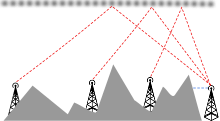
While the groundwave (blue) cannot propagate, the refracted skywaves (red) achieve HF coverage within the common first hop (~500km).
The most reliable frequencies for NVIS communications are between 1.8 MHz and 8 MHz. Above 8 MHz, the probability of success begins to decrease, dropping to near zero at 30 MHz. Usable frequencies are dictated by local ionospheric conditions, which have a strong systematic dependence on geographical location. Common bands used in amateur radio at mid-latitudes are 3.5 MHz at night and 7 MHz during daylight, with experimental use of 5 MHz (60 meters) frequencies. During winter nights at the bottom of the sunspot cycle, the 1.8 MHz band may be required. [3] Broadcasting uses the tropical broadcast bands between 2.3 and 5.06 MHz, and the international broadcast bands between 3.9 and 6.2 MHz. Military NVIS communications mostly take place on 2–4 MHz at night and on 5–7 MHz during daylight.
Optimum NVIS frequencies tend to be higher towards the tropics and lower towards the arctic regions. They are also higher during high sunspot activity years. The usable frequencies change from day to night, because sunlight causes the lowest layer of the ionosphere, called the D layer, to increase, causing attenuation of low frequencies during the day [4] while the maximum usable frequency (MUF) which is the critical frequency of the F layer rises with greater sunlight. Real time maps of the critical frequency are available. [5] Use of a frequency about 15% below the critical frequency should provide reliable NVIS service. This is sometimes referred to as the optimum working frequency or FOT.
NVIS is most useful in mountainous areas where line-of-sight propagation is ineffective, or when the communication distance is beyond the 50 mile (80 km) range of groundwave (or the terrain is so rugged and barren that groundwave is not effective), and less than the 300–1500 mile (500–2500 km) range of lower-angle sky-wave propagation. Another interesting aspect of NVIS communication is that direction finding of the sender is more difficult than for ground-wave communication (i.e. VHF or UHF). For broadcasters, NVIS allows coverage of an entire medium-sized country at much lower cost than with VHF (FM), and daytime coverage, similar to mediumwave (AM broadcast) nighttime coverage at lower cost and often with less interference.
Antennas
An NVIS antenna configuration is a horizontally polarized (parallel with the surface of the earth) radiating element that is from 1/20th wavelength (λ) to 1/4 wavelength above the ground. Optimum height is about 1/4 wavelength, and high angle radiation declines only slightly for heights up to about 3/8 wavelength. [6] That proximity to the ground forces the majority of the radiation to go straight up. Overall efficiency of the antenna can be increased by placing a ground wire slightly longer than the antenna parallel to and directly underneath the antenna. One source says that a single ground wire can provide antenna gain in the 3–6 dB range.[7] Another source indicates 2 dB for a single wire and nearly 4 dB for multiple ground wires.[8] Ground wires are more necessary when using lower dipoles over poor soils as without them considerable energy goes into heating the ground.
Depending on the specific requirements, various antennas (i.e. Sloper, T2FD, Dipole) can be used for NVIS communication, with horizontal dipoles or inverted V dipoles at about 0.2 wavelengths above ground giving the best results on transmit and at about 0.16 wavelengths on receive, according to military sources and an extensive study by Dutch researchers. [9] [10] Very low antennas are much inferior on transmit, less so on receive, where both noise and signal are attenuated.
Significant increases in communication will obviously be realized when both the transmitting station and the receiving station use NVIS configuration for their antennas. In particular for low profile operations NVIS antennas are a good option.[11]
For broadcasting, typical antennas consist of a dipole about 1/4 wavelength above ground, or arrays of such dipoles.[12] Up to 16 dipoles can be used, allowing strong signals with relatively low power by concentrating the signal in a smaller area. Limiting the coverage may be dictated by licensing, language or political considerations. Arrays of dipoles can be used to "slew" the pattern, so that the transmitter need not be in the center of the coverage footprint. Broadcast NVIS antennas usually use an extensive ground screen to increase gain and stabilize the pattern and feed impedance with changing ground moisture.
AS-2259 antenna

A military NVIS antenna is the AS-2259 Antenna,[13] which consists of two V-shaped dipoles: The four dipole wires also serve as guy rope for the antenna mast. An alternative configuration consists of a transmitting loop antenna which is configured for maximum signal transmission upwards.[14]
See also
References
- Broadcasting in Band 7 (HF) in the Tropical Zone, International Radio Consultative Committee, International Telecommunications Union, Geneva, 1969
- The Emergency Communications Antenna, By Stephen C. Finch, AIØW http://www.w8ne.com/Files/NVIS%20nvis_AI0W.pdf
- http://hamwaves.com/nvis/en/index.html
- "An analytical study of HF communications between provincial PREOC-s and the North Shore Emergency Management office at VE7NSR" (PDF).
- "World Ionospheric Map". Commonwealth of Australia Bureau of Meteorology.
- Brown, Jim. "Planning Antennas" (PDF). k9yc.com/publish.htm. Jim Brown, K9YC. Retrieved 30 April 2017.
- Hawker (2005), pp. 89
- http://www.w8ji.com/nvis_n_v_i_s_antenna.htm NVIS Antennas
- G. E. Barker, J. Taylor, and G. H. Hagn, “Summary of measurements and modeling of the radiation patterns of simple field antennas in open (level) terrain, mountains and forests,” U.S. Army Electronic Command, Aberdeen Proving Ground, MD, USA, Spec. Tech. Rep. 45, December 1971.
- "Archived copy" (PDF). Archived from the original (PDF) on 2017-04-11. Retrieved 2017-04-10.CS1 maint: archived copy as title (link)
- Space Challenged NVIS Antenna http://harriscountyares.org/training/KNW/KNW-119.pdf
- Broadcasting in Band 7, page 39
- AS-2259 Antenna Manual http://www.radiomanual.info/schemi/Surplus_Accessories/AS-2259_antenna_serv_user_TM11-5985-379-14P_1986.pdf
- Hawker (1999), pp. 33
- Antony Wedgwood, G0TJD; Goldstein, J. A. (April 2001). "Near Vertical Incidence Skywave". The Vintage and Military Amateur Radio Society Newsletter. 16: 7–11. Bibcode:1995nrl..reptS....W.
- Hawker, Pat (1999). Technical Topics Scrapbook 1990-1994. Potters bar,UK: Radio Society of Great Britain. pp. 33–34, 64–65. ISBN 978-1-872309-51-4.
- Hawker, Pat (2005). Technical Topics Scrapbook 2000-2004. Potters bar,UK: Radio Society of Great Britain. pp. 61, 89–90, 109–110, 126, 143, 154. ISBN 978-1-905086-05-4.
- Walden, M. (March 2008). "Extraordinary Wave NVIS Propagation at 5 MHz". RadCom. 84 (3): 57–62.