Heat pump and refrigeration cycle
Thermodynamic heat pump cycles or refrigeration cycles are the conceptual and mathematical models for heat pump, air conditioning and refrigeration systems. A heat pump is a mechanical system that allows for the transmission of heat from one location (the "source") at a lower temperature to another location (the "sink" or "heat sink") at a higher temperature.[1] Thus a heat pump may be thought of as a "heater" if the objective is to warm the heat sink (as when warming the inside of a home on a cold day), or a "refrigerator" or “cooler” if the objective is to cool the heat source (as in the normal operation of a freezer). In either case, the operating principles are close.[2] Heat is moved from a cold place to a warm place.
| Thermodynamics | ||||||||||||
|---|---|---|---|---|---|---|---|---|---|---|---|---|
 The classical Carnot heat engine | ||||||||||||
|
||||||||||||
| ||||||||||||


Thermodynamic cycles
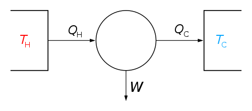
According to the second law of thermodynamics heat cannot spontaneously flow from a colder location to a hotter area; work is required to achieve this.[3] An air conditioner requires work to cool a living space, moving heat from the cooler interior (the heat source) to the warmer outdoors (the heat sink). Similarly, a refrigerator moves heat from inside the cold icebox (the heat source) to the warmer room-temperature air of the kitchen (the heat sink). The operating principle of ideal heat engine was described mathematically using Carnot cycle by Sadi Carnot in 1824. An ideal refrigeration or a heat pump system can be thought of as an ideal heat engine that is operating in a reverse Carnot cycle.[4]
Heat pump and refrigeration cycles can be classified as vapor compression, vapor absorption, gas cycle, or Stirling cycle types.
Vapor-compression cycle
The vapor-compression cycle is used in most household refrigerators as well as in light commercial, commercial, and industrial refrigeration systems. Figure 1 provides a schematic diagram of the components of a typical vapor-compression refrigeration system.

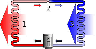
The thermodynamics of the cycle can be analysed on a diagram[5][6] as shown in Figure 2. In this cycle, a circulating working fluid commonly called refrigerant such as Freon enters the compressor as a low pressure and low temperature vapor. The vapor is compressed at constant entropy and exits the compressor superheated. The superheated vapor travels through the condenser which first cools and removes the superheat and then condenses the vapor into a liquid when releasing additional heat at constant pressure and temperature. The liquid refrigerant goes through the expansion valve (also called a throttle valve) where its pressure abruptly decreases, causing flash evaporation and auto-refrigeration of, typically,a small portion of the liquid.[7]

That results in a mixture of liquid and vapor at a lower temperature and pressure. The cold liquid-vapor mixture then travels through the evaporator coil or tubes and is completely vaporized by cooling the warm air (from the space being refrigerated) being blown by a fan across the evaporator coil or tubes. The resulting refrigerant vapor returns to the compressor inlet to complete the thermodynamic cycle.[8]
The above discussion is based on the ideal vapor-compression refrigeration cycle, and does not take into account real-world effects like frictional pressure drop in the system, slight thermodynamic irreversibility during the compression of the refrigerant vapor, or non-ideal gas behavior (if any).[4]
Vapor absorption cycle
In the early years of the twentieth century, the vapor absorption cycle using water-ammonia systems was popular and widely used but, after the development of the vapor compression cycle, it lost much of its importance because of its low coefficient of performance (about one fifth of that of the vapor compression cycle). Nowadays, the vapor absorption cycle is used only where heat is more readily available than electricity, such as industrial waste heat, solar thermal energy by solar collectors, or off-the-grid refrigeration in recreational vehicles.
The absorption cycle is similar to the compression cycle, except for the method of raising the pressure of the refrigerant vapor. In the absorption system, the compressor is replaced by an absorber and a generator. The absorber dissolves the refrigerant in a suitable liquid (dilute solution) and therefore the dilute solution becomes a strong solution. Then, a liquid pump would move the strong solution from the absorber to a generator where, on heat addition, the temperature and pressure increase. Then the refrigerant vapor is released from the strong solution, which turns into the dilute solution and is moved back to the absorber by the liquid pump. Some work is required by the liquid pump but, for a given quantity of refrigerant, it is much smaller than needed by the compressor in the vapor compression cycle. However, the generator requires a heat source, which would consume heating energy unless waste heat is used. In an absorption refrigerator, a suitable combination of refrigerant and absorbent is used. The most common combinations are ammonia (refrigerant) and water (absorbent), and water (refrigerant) and lithium bromide (absorbent).
Absorption refrigeration systems can be powered by fossil energies (i.e., coal, oil, natural gas, etc) or renewable energies (i.e., waste-heat recovery, biomass, solar energy).[9]
Gas cycle
When the working fluid is a gas that is compressed and expanded but does not change phase, the refrigeration cycle is called a gas cycle. Air is most often this working fluid. As there is no condensation and evaporation intended in a gas cycle, components corresponding to the condenser and evaporator in a vapor compression cycle are the hot and cold gas-to-gas heat exchangers.
For given extreme temperatures, a gas cycle may be less efficient than a vapor compression cycle because the gas cycle works on the reverse Brayton cycle instead of the reverse Rankine cycle. As such, the working fluid never receives or rejects heat at constant temperature. In the gas cycle, the refrigeration effect is equal to the product of the specific heat of the gas and the rise in temperature of the gas in the low temperature side. Therefore, for the same cooling load, gas refrigeration cycle machines require a larger mass flow rate, which in turn increases their size.
Because of their lower efficiency and larger bulk, air cycle coolers are not often applied in terrestrial refrigeration. The air cycle machine is very common, however, on gas turbine-powered jet airliners since compressed air is readily available from the engines' compressor sections. These jet aircraft's cooling and ventilation units also serve the purpose of heating and pressurizing the aircraft cabin.
Stirling engine
The Stirling cycle heat engine can be driven in reverse, using a mechanical energy input to drive heat transfer in a reversed direction (i.e. a heat pump, or refrigerator). There are several design configurations for such devices that can be built. Several such setups require rotary or sliding seals, which can introduce difficult tradeoffs between frictional losses and refrigerant leakage.
Reversed Carnot cycle
The Carnot cycle is a reversible cycle so the four processes that comprise it, two isothermal and two isentropic, can also be reversed. When a Carnot cycle runs reversely, it is called a reversed Carnot cycle. A refrigerator or heat pump that acts on the reversed Carnot cycle is called a Carnot refrigerator or Carnot heat pump respectively. In the first stage of this cycle, the refrigerant absorbs heat isothermally from a low-temperature source, TL, in the amount QL. Next, the refrigerant is isentropically compressed and its temperature rises to that of the high-temperature source, TH. Then at this high temperature, the refrigerant rejects heat isothermally in the amount QH. Also during this stage, the refrigerant changes from a saturated vapor to a saturated liquid in the condenser. Lastly, the refrigerant expands isentropically until its temperature falls to that of the low-temperature source, TL.[2]
Coefficient of performance
The efficiency of a refrigerator or heat pump is given by a parameter called the coefficient of performance (COP).
The equation is:

where
- is the useful heat supplied or removed by the considered system.
- is the work required by the considered system.


The Detailed COP of a refrigerator is given by the following equation:
- COPR = (Desired Output)/(Required Input) = (Cooling Effect)/(Work Input) = QL/Wnet,in
The COP of a heat pump (sometimes referred to as coefficient of amplification COA), given by the following equation, where QH = QL + Wnet,in:
- COPHP = (Desired Output)/(Required Input) = (Heating Effect)/(Work Input) = QH/Wnet,in = 1 + (QL/Wnet,in)
Both the COP of a refrigerator and a heat pump can be greater than one. Combining these two equations results in:
- COPHP = COPR + 1 for fixed values of QH and QL
This implies that COPHP will be greater than one because COPR will be a positive quantity. In a worst-case scenario, the heat pump will supply as much energy as it consumes, making it act as a resistance heater. However, in reality, as in home heating, some of QH is lost to the outside air through piping, insulation, etc., thus making the COPHP drop below unity when the outside air temperature is too low. Therefore, the system used to heat houses uses fuel.[2]
For Carnot refrigerators and heat pumps, COP can be expressed in terms of temperatures:
- COPR,Carnot = TL/(TH-TL) = 1/((TH/TL) - 1)
- COPHP,Carnot = TH/(TH-TL) = 1/(1 - (TL/TH))
References
- The Systems and Equipment volume of the ASHRAE Handbook, ASHRAE, Inc., Atlanta, GA, 2004
- Cengel, Yunus A. and Michael A. Boles (2008). Thermodynamics: An Engineering Approach (6th ed.). McGraw-Hill. ISBN 0-07-330537-5.
- Fundamentals of Engineering Thermodynamics, by Howell and Buckius, McGraw-Hill, New York.
- "Description 2017 ASHRAE Handbook—Fundamentals". www.ashrae.org. Retrieved 2020-06-13.
- The Ideal Vapor-Compression Cycle Archived 2007-02-26 at the Wayback Machine
- "Scroll down to "The Basic Vapor Compression Cycle and Components"". Archived from the original on 2006-06-30. Retrieved 2007-06-02.
- "Thermostatic Expansion Values: A Guide to Understanding TXVs". AC & Heating Connect. 2013-06-24. Retrieved 2020-06-15.
- Althouse, Andrew (2004). Modern Refrigeration and Air Conditioning. The Goodheart-Wilcox Company, Inc. p. 109. ISBN 1-59070-280-8.
- "Absorption Refrigeration - an overview | ScienceDirect Topics". www.sciencedirect.com. Retrieved 2020-06-09.
- Notes
- Turns, Stephen (2006). Thermodynamics: Concepts and Applications. Cambridge University Press. p. 756. ISBN 0-521-85042-8.
- Dincer, Ibrahim (2003). Refrigeration Systems and Applications. John Wiley and Sons. p. 598. ISBN 0-471-62351-2.
- Whitman, Bill (2008). Refrigeration and Air conditioning Technology. Delmar.