Electronic symbol
An electronic symbol is a pictogram used to represent various electrical and electronic devices or functions, such as wires, batteries, resistors, and transistors, in a schematic diagram of an electrical or electronic circuit. These symbols are largely standardized internationally today, but may vary from country to country, or engineering discipline, based on traditional conventions.

Standards for symbols
The graphic symbols used for electrical components in circuit diagrams are covered by national and international standards, in particular:
- IEC 60617 (also known as British Standard BS 3939).
- There is also IEC 61131-3 - for ladder-logic symbols.
- JIC JIC (Joint Industrial Council) symbols as approved and adopted by the NMTBA (National Machine Tool Builders Association). They have been extracted from the Appendix of the NMTBA Specification EGPl-1967
- ANSI Y32.2-1975 (also known as IEEE Std 315-1975 or CSA Z99-1975)
- IEEE Std 91/91a: graphic symbols for logic functions (used in digital electronics). It is referenced in ANSI Y32.2/IEEE Std 315.
- Australian Standard AS 1102. (Based on a slightly modified version of IEC 60617, Withdrawn without replacement with a recommendation to use IEC 60617)
The number of standards leads to confusion and errors.[1] Symbols usage is sometimes unique to engineering disciplines and national or local variations to international standards exist. For example, lighting and power symbols used as part of architectural drawings may be different from symbols for devices used in electronics.
Common electronic symbols
Symbols shown are typical examples, not a complete list.[2][3]
Traces
 IEC-style trace junction
 Trace crossing
Grounds
Optionally, the triangle in the following symbol may be filled in.

 Signal/Low noise ground (GND) symbol
 IEC-style chassis-ground symbol
Sources
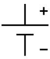 Battery, single cell
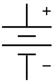 Battery, multi cell
 Solar cell, aka Photovoltaic cell.
 Voltage source
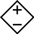 Controlled voltage source
 Current source
 Controlled current source
 AC voltage source
Resistors
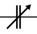
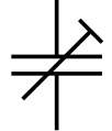
It is very common for potentiometer and rheostat symbols to be used for many types of variable resistors, including trimmers.
%2C_and_Potentiometer_symbols.svg.png) (a) resistor, (b) rheostat (variable resistor), and (c) potentiometer (All of them are ANSI style symbols)
(a) resistor, (b) rheostat (variable resistor), and (c) potentiometer (All of them are ANSI style symbols) (a) resistor, (b) rheostat (variable resistor), and (c) potentiometer (All of them are IEC style symbols)
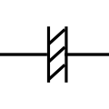
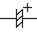
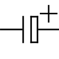
Capacitors


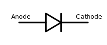
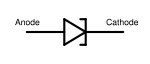
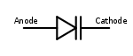
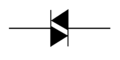
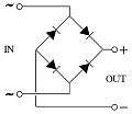
Diodes
Optionally, the triangle in these symbols may be filled in. There are multiple ways to draw a Bridge Rectifier symbol.

 Light-emitting diode (LED)

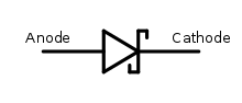
 Silicon-controlled rectifier (SCR)
Inductors

 Inductor with magnetic core (IEEE Std 315)
 Ferrite bead (IEEE Std 315)
Transformers

 Transformer with center tap on secondary winding (right side)
 Transformer with two secondary windings (right side)
 Current Transformer
 Zero-Sequence Current Transformer (ZSCT) (also known as a window-type current transformer)
 Bushing-Type Current Transformer
 Voltage Transformer
Transistors
Unipolar
Optionally, these symbols may include a circle.


 Metal-Oxide-Semiconductor Field-Effect Transistor
 Enhancement mode, N-channel MOSFET
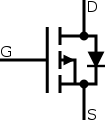 Enhancement mode, P-channel MOSFET
Bipolar
Optionally, these symbols may include a circle.
.svg.png) NPN bipolar junction transistor (BJT)
NPN bipolar junction transistor (BJT).svg.png) PNP bipolar junction transistor (BJT)
PNP bipolar junction transistor (BJT) NPN Darlington
 PNP Darlington
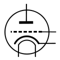
Vacuum tubes


Switches
 Switch, Single Pole/Single Throw (SPST)
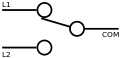 Switch, Single Pole/Double Throw (SPDT)
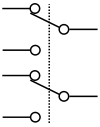 Switch, Double Pole/Double Throw (DPDT)
 Pushbutton, Momentary or Spring-Return, make (IEEE Std 315)
 Pushbutton, Momentary or Spring-Return, break (IEEE Std 315)
 Pushbutton, Momentary or Spring-Return, two circuit (IEEE Std 315)
Relays
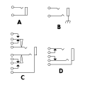
 American-style relays, SPST, SPDT, DPST, DPDT
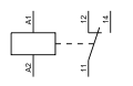 IEC relay symbol, SPDT
Lamps
 Indicating lamp (IEEE Std 315-1975)
 Incandescent lamp
 Incandescent light bulb (as an indicator)
 Light bulb
Current limiters

 Moulded Case Circuit Breaker (MCCB)
Electro-acoustic devices
 IEC-style microphone
 Microphone (IEEE Std 315)
 Loudspeaker (IEEE Std 315)
Antennas


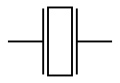
 Loop antenna (IEEE Std 315)
Connectors
ICs
 Operational amplifier (OpAmp) or Comparator
Miscellaneous devices

Historical electronic symbols
The shape of electronic symbols have changed over time. Some symbols were more prevalent in some countries. The following are historic electronic symbols that might be found in old electronic books and schematics.
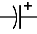
Capacitors (historical)
References
- Guidelines for Drawing Schematics
- Circuit Symbols for all Electronic Components. Talking Electronics, 2013. Retrieved 01 Apr 2015.
- Electrical Symbols & Electronic Symbols. RapidTables, 2012. Retrieved 17 April 2016.
Further reading
- Beginner's Guide to Reading Schematics; 4th Ed; Stan Gibilisco; McGraw-Hill, 224 pages; 2018; ISBN 978-1260031119.
- How to Read Electronic Circuit Diagrams; 2nd Ed; Brown, Lawrence, Whitson; Tab Books; 214 pages; 1988; ISBN 978-0830628803.
- How to Read Schematic Diagrams; 4th Ed; Donald Herrington; Sams Publishing; 160 pages; 1986; ISBN 978-0672224577. (2nd Ed in 1973)
External links
| Wikimedia Commons has media related to Electrical symbols. |
- IEEE Standard American National Standard Canadian Standard Graphic Symbols for Electrical and Electronics Diagrams (Including Reference Designation Letters)
- International standard IEC 60617 DB Graphical symbols for diagrams
- Electrical Schematic Symbols
- Collection of Open Source Electrical, Pneumatic, Hydraulic and Electronic Symbols
- Circuit Symbols of Electronic Components
- Electrical & Electronic Drawing Symbols
- Collection of Electrical and Electronic Symbols
- Circuit Schematic Symbols
- Collection of Electrical and Electronic Schematic Symbols