AND gate
The AND gate is a basic digital logic gate that implements logical conjunction - it behaves according to the truth table to the right. A HIGH output (1) results only if all the inputs to the AND gate are HIGH (1). If none or not all inputs to the AND gate are HIGH, a LOW output results. The function can be extended to any number of inputs.
| INPUT | OUTPUT | |
|---|---|---|
| A | B | A AND B |
| 0 | 0 | 0 |
| 0 | 1 | 0 |
| 1 | 0 | 0 |
| 1 | 1 | 1 |
Symbols
There are three symbols for AND gates: the American (ANSI or 'military') symbol and the IEC ('European' or 'rectangular') symbol, as well as the deprecated DIN symbol. Additional inputs can be added as needed. For more information see Logic Gate Symbols. It can also be denoted as symbol "^" or "&".
 |
 |
 |
| MIL/ANSI Symbol | IEC Symbol | DIN Symbol |
The AND gate with inputs A and B and output C implements the logical expression . This expression also may be denoted as C=A^B or C=A&B.

Implementations
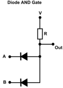 AND gate using diodes
 AND gate using transistors
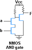 NMOS AND gate
An AND gate is usually designed using N-channel (pictured) or P-channel MOSFETs. The digital inputs a and b cause the output F to have the same result as the AND function.
Analytical representation
is the analytical representation of AND gate:


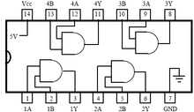
IC package
AND gates are available in IC packages. The 7408 IC is a well known QUAD 2-Input AND GATES and contains four independent gates each of which performs the logic AND function.
See also
| Wikimedia Commons has media related to AND gates. |
References
- Mano, M. Morris and Charles R. Kime. Logic and Computer Design Fundamentals, Third Edition. Prentice Hall, 2004. p. 73.
 | ||
| ||


