NOR logic
A NOR gate is a logic gate which gives a positive output only when both inputs are negative.

Like NAND gates, NOR gates are so-called "universal gates" that can be combined to form any other kind of logic gate. For example, the first embedded system, the Apollo Guidance Computer, was built exclusively from NOR gates, about 5,600 in total for the later versions. Today, integrated circuits are not constructed exclusively from a single type of gate. Instead, EDA tools are used to convert the description of a logical circuit to a netlist of complex gates (standard cells) or transistors (full custom approach).
NOR
A NOR gate is logically an inverted OR gate. By itself has the following truth table:
| |||||||||||||||||||||
|
Q = A NOR B
| |||||||||||||||||||||
Making other gates by using NOR gates
A NOR gate is a universal gate, meaning that any other gate can be represented as a combination of NOR gates.
NOT
This is made by joining the inputs of a NOR gate. As a NOR gate is equivalent to an OR gate leading to NOT gate, this automatically sees to the "OR" part of the NOR gate, eliminating it from consideration and leaving only the NOT part.
| Desired NOT Gate | NOR Construction | |||||||||
|---|---|---|---|---|---|---|---|---|---|---|
 |  | |||||||||
| Q = NOT( A ) | = A NOR A | |||||||||
| ||||||||||
OR
An OR gate is made by inverting the output of a NOR gate. Note that we already know that a NOT gate is equivalent to a NOR gate with its inputs joined.
| Desired OR Gate | NOR Construction | ||||||||||||||||||||
|---|---|---|---|---|---|---|---|---|---|---|---|---|---|---|---|---|---|---|---|---|---|
 |  | ||||||||||||||||||||
| Q = A OR B | = ( A NOR B ) NOR ( A NOR B ) | ||||||||||||||||||||
| |||||||||||||||||||||
AND
An AND gate gives a 1 output when both inputs are 1. Therefore, an AND gate is made by inverting the inputs of a NOR gate. Again, note that a NOT gate is equivalent to a NOR with its inputs joined.
| Desired AND Gate | NOR Construction | ||||||||||||||||||||
|---|---|---|---|---|---|---|---|---|---|---|---|---|---|---|---|---|---|---|---|---|---|
 |  | ||||||||||||||||||||
| Q = A AND B | = ( A NOR A ) NOR ( B NOR B ) | ||||||||||||||||||||
| |||||||||||||||||||||
NAND
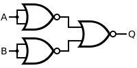
A NAND gate is made by inverting the output of an AND gate. the word NAND means that it is not and.as the name suggests that it will give 0 when both the inputs are 1.
| Desired NAND Gate | NOR Construction | ||||||||||||||||||||
|---|---|---|---|---|---|---|---|---|---|---|---|---|---|---|---|---|---|---|---|---|---|
 |  | ||||||||||||||||||||
| Q = A NAND B | = [ ( A NOR A ) NOR ( B NOR B ) ] NOR [ ( A NOR A ) NOR ( B NOR B ) ] | ||||||||||||||||||||
| |||||||||||||||||||||
XNOR
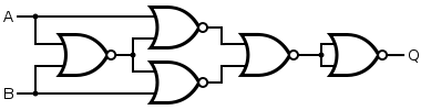
An XNOR gate is made by connecting four NOR gates as shown below. This construction entails a propagation delay three times that of a single NOR gate.
| Desired XNOR Gate | NOR Construction | ||||||||||||||||||||
|---|---|---|---|---|---|---|---|---|---|---|---|---|---|---|---|---|---|---|---|---|---|
 | 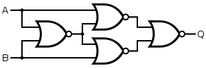 | ||||||||||||||||||||
| Q = A XNOR B | = [ A NOR ( A NOR B ) ] NOR [ B NOR ( A NOR B ) ] | ||||||||||||||||||||
| |||||||||||||||||||||
Alternatively, an XNOR gate is made by considering the conjunctive normal form , noting from de Morgan's Law that a NOR gate is an inverted-input AND gate. This construction uses five gates instead of four.

| Desired Gate | NOR Construction |
|---|---|
| 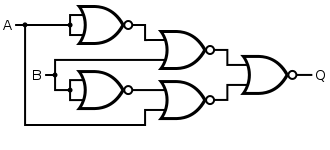 |
| Q = A XNOR B | = [ B NOR ( A NOR A ) ] NOR [ A NOR ( B NOR B ) ] |
XOR
An XOR gate is made by considering the conjunctive normal form , noting from de Morgan's Law that a NOR gate is an inverted-input AND gate. This construction entails a propagation delay three times that of a single NOR gate and uses five gates.

| Desired XOR Gate | NOR Construction | ||||||||||||||||||||
|---|---|---|---|---|---|---|---|---|---|---|---|---|---|---|---|---|---|---|---|---|---|
 | 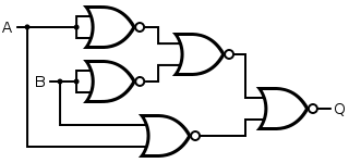 | ||||||||||||||||||||
| Q = A XOR B | = [ ( A NOR A ) NOR ( B NOR B ) ] NOR ( A NOR B ) | ||||||||||||||||||||
| |||||||||||||||||||||
Alternatively, the 4-gate version of the XNOR gate can be used with an inverter. This construction has a propagation delay four times (instead of three times) that of a single NOR gate.
| Desired Gate | NOR Construction |
|---|---|
|  |
| Q = A XOR B | = { [ A NOR ( A NOR B ) ] NOR [ B NOR ( A NOR B ) ] } NOR { [ A NOR ( A NOR B ) ] NOR [ B NOR ( A NOR B ) ] } |
See also
- NAND logic — Like NOR gates, NAND gates are also universal gates.
- Functional completeness