Turbofan

| Part of a series on |
| Aircraft propulsion |
|---|
|
Shaft engines: driving propellers, rotors, ducted fans or propfans |
| Reaction engines |
| Others |
.jpg)
.JPG)
The turbofan or fanjet is a type of airbreathing jet engine that is widely used in aircraft propulsion. The word "turbofan" is a portmanteau of "turbine" and "fan": the turbo portion refers to a gas turbine engine which achieves mechanical energy from combustion,[1] and the fan, a ducted fan that uses the mechanical energy from the gas turbine to accelerate air rearwards. Thus, whereas all the air taken in by a turbojet passes through the turbine (through the combustion chamber), in a turbofan some of that air bypasses the turbine. A turbofan thus can be thought of as a turbojet being used to drive a ducted fan, with both of these contributing to the thrust.
The ratio of the mass-flow of air bypassing the engine core divided by the mass-flow of air passing through the core is referred to as the bypass ratio. The engine produces thrust through a combination of these two portions working together; engines that use more jet thrust relative to fan thrust are known as low-bypass turbofans, conversely those that have considerably more fan thrust than jet thrust are known as high-bypass. Most commercial aviation jet engines in use today are of the high-bypass type,[2][3] and most modern military fighter engines are low-bypass.[4][5] Afterburners are not used on high-bypass turbofan engines but may be used on either low-bypass turbofan or turbojet engines.
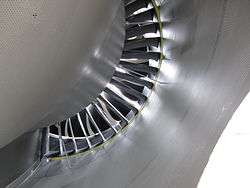
Modern turbofans have either a large single-stage fan or a smaller fan with several stages. An early configuration combined a low-pressure turbine and fan in a single rear-mounted unit.
Principles
Turbofans were invented to circumvent an awkward feature of turbojets, which was that they were inefficient for subsonic flight. To raise the efficiency of a turbojet, the obvious approach would be to increase the burner temperature, to give better Carnot efficiency and fit larger compressors and nozzles. However, while that does increase thrust somewhat, the exhaust jet leaves the engine with even higher velocity, which at subsonic flight speeds, takes most of the extra energy with it, wasting fuel.
Instead, a turbofan can be thought of as a turbojet being used to drive a ducted fan, with both of those contributing to the thrust. Whereas all the air taken in by a turbojet passes through the turbine (through the combustion chamber), in a turbofan some of that air bypasses the turbine.
Because the turbine has to additionally drive the fan, the turbine is larger and has larger pressure and temperature drops, and so the nozzles are smaller. This means that the exhaust velocity of the core is reduced. The fan also has lower exhaust velocity, giving much more thrust per unit energy (lower specific thrust). The overall effective exhaust velocity of the two exhaust jets can be made closer to a normal subsonic aircraft's flight speed. In effect, a turbofan emits a large amount of air more slowly, whereas a turbojet emits a smaller amount of air quickly, which is a far less efficient way to generate the same thrust.
The ratio of the mass-flow of air bypassing the engine core compared to the mass-flow of air passing through the core is referred to as the bypass ratio. The engine produces thrust through a combination of these two portions working together; engines that use more jet thrust relative to fan thrust are known as low-bypass turbofans, conversely those that have considerably more fan thrust than jet thrust are known as high-bypass. Most commercial aviation jet engines in use today are of the high-bypass type,[6][3] and most modern military fighter engines are low-bypass.[4][7] Afterburners are not used on high-bypass turbofan engines but may be used on either low-bypass turbofan or turbojet engines.
Bypass ratio
The bypass ratio (BPR) of a turbofan engine is the ratio between the mass flow rate of the bypass stream to the mass flow rate entering the core.[8] A 10:1 bypass ratio, for example, means that 10 kg of air passes through the bypass duct for every 1 kg of air passing through the core.
Turbofan engines are usually described in terms of BPR, which together with overall pressure ratio, turbine inlet temperature and fan pressure ratio are important design parameters. In addition bpr is quoted for turboprop and unducted fan installations because their high propulsive efficiency gives them the overall efficiency characteristics of very high bypass turbofans. This allows them to be shown together with turbofans on plots which show trends of reducing specific fuel consumption (SFC) with increasing BPS. BPR can also be quoted for lift fan installations where the fan airflow is remote from the engine and doesn't physically touch the engine core.
Bypass provides a lower fuel consumption for the same thrust.
If all the gas power from a gas turbine is converted to kinetic energy in a propelling nozzle, the aircraft is best suited to high supersonic speeds. If it is all transferred to a separate big mass of air with low kinetic energy, the aircraft is best suited to zero speed (hovering). For speeds in between, the gas power is shared between a separate airstream and the gas turbine's own nozzle flow in a proportion which gives the aircraft performance required. The trade off between mass flow and velocity is also seen with propellers and helicopter rotors by comparing disc loading and power loading.[9] For example, the same helicopter weight can be supported by a high power engine and small diameter rotor or, for less fuel, a lower power engine and bigger rotor with lower velocity through the rotor.
Bypass usually refers to transferring gas power from a gas turbine to a bypass stream of air to reduce fuel consumption and jet noise. Alternatively, there may be a requirement for an afterburning engine where the sole requirement for bypass is to provide cooling air. This sets the lower limit for bpr and these engines have been called "leaky" or continuous bleed turbojets[10] (General Electric YJ-101 bpr 0.25) and low bpr turbojets[11] (Pratt & Whitney PW1120). Low bpr (0.2) has also been used to provide surge margin as well as afterburner cooling for the Pratt & Whitney J58.[12]
Efficiency
Since the efficiency of propulsion is a function of the relative airspeed of the exhaust to the surrounding air, propellers are most efficient for low speed, pure jets for high speeds, and ducted fans in the middle. Turbofans are thus the most efficient engines in the range of speeds from about 500 to 1,000 km/h (310 to 620 mph), the speed at which most commercial aircraft operate.[13][14] Turbofans retain an efficiency edge over pure jets at low supersonic speeds up to roughly Mach 1.6 (1,960.1 km/h; 1,217.9 mph).
In a zero-bypass (turbojet) engine the high temperature and high pressure exhaust gas is accelerated by expansion through a propelling nozzle and produces all the thrust. The compressor absorbs all the mechanical power produced by the turbine. In a bypass design extra turbines drive a ducted fan that accelerates air rearward from the front of the engine. In a high-bypass design, the ducted fan and nozzle produce most of the thrust. Turbofans are closely related to turboprops in principle because both transfer some of the gas turbine's gas power, using extra machinery, to a bypass stream leaving less for the hot nozzle to convert to kinetic energy. Turbofans represent an intermediate stage between turbojets, which derive all their thrust from exhaust gases, and turbo-props which derive minimal thrust from exhaust gases (typically 10% or less).[15] Extracting shaft power and transferring it to a bypass stream introduces extra losses which are more than made up by the improved propulsive efficiency. The turboprop at its best flight speed gave significant fuel savings over a turbojet even though an extra turbine, a gearbox and a propeller were added to the turbojet's low-loss propelling nozzle.[16] The turbofan has additional losses from its extra turbines, fan, bypass duct and extra propelling nozzle compared to the turbojet's single nozzle.
Thrust
While a turbojet engine uses all of the engine's output to produce thrust in the form of a hot high-velocity exhaust gas jet, a turbofan's cool low-velocity bypass air yields between 30% and 70% of the total thrust produced by a turbofan system.[17]
The thrust (FN) generated by a turbofan depends on the effective exhaust velocity of the total exhaust, as with any jet engine, but because two exhaust jets are present the thrust equation can be expanded as:[18]

where:
| ṁ e | = the mass rate of hot combustion exhaust flow from the core engine |
| ṁo | = the mass rate of total air flow entering the turbofan = ṁc + ṁf |
| ṁc | = the mass rate of intake air that flows to the core engine |
| ṁf | = the mass rate of intake air that bypasses the core engine |
| vf | = the velocity of the air flow bypassed around the core engine |
| vhe | = the velocity of the hot exhaust gas from the core engine |
| vo | = the velocity of the total air intake = the true airspeed of the aircraft |
| BPR | = Bypass Ratio |
Nozzles
The cold duct and core duct's nozzle systems are relatively complex due to there being two exhaust flows.
In high bypass engines the fan is generally situated in a short duct near the front of the engine and typically has a convergent cold nozzle, with the tail of the duct forming a low pressure ratio nozzle that under normal conditions will choke creating supersonic flow patterns around the core.
The core nozzle is more conventional, but generates less of the thrust, and depending on design choices, such as noise considerations, may conceivably not choke.[19]
In low bypass engines the two flows may combine within the ducts, and share a common nozzle, which can be fitted with afterburner.
Noise
Most of the air flow through a high-bypass turbofan is lower velocity bypass flow: even when combined with the much higher velocity engine exhaust, the average exhaust velocity is considerably lower than in a pure turbojet. Turbojet engine noise is predominately jet noise from the high exhaust velocity, therefore turbofan engines are significantly quieter than a pure-jet of the same thrust, and jet noise is no longer the predominant source. Other noise sources are the fan, compressor and turbine.[20]
Modern commercial aircraft employ high-bypass-ratio (HBPR) engines with separate flow, non-mixing, short-duct exhaust systems. These propulsion systems are known to generate significantly high noise levels due to the high speed, high temperature, and high pressure of the exhaust jet, especially during high thrust conditions such as those required for takeoff. The primary source of jet noise is the turbulent mixing of shear layers in the engine’s exhaust. These shear layers contain instabilities that lead to highly turbulent vortices that generate the pressure fluctuations responsible for sound. In order to reduce the noise associated with jet flow, the aerospace industry has focused on developing technologies to disrupt shear layer turbulence and reduce the overall noise produced.
Turbofan engine noise propagates both upstream via the inlet and downstream via the primary nozzle and the by-pass duct. The main noise sources are the turbine and the compressor, the jet and the fan. The contribution of each noise source significantly evolved in the late 20th century:[21] in typical 1960s design the jet was the main source whereas in modern turbofans the fan is the main noise source.
The fan noise is a tonal noise and its signature depends on the fan rotational speed:
- at low speed, the fan noise is due to the interaction of the blades with the distorted flow injected in the engine; this happens for example during the approach;
- at high engine ratings, the fan tip is supersonic and this allows intense rotor-locked duct modes to propagate upstream; this noise is known as "buzz saw" and is typical at take-off.[22]
All modern turbofan engines are equipped with acoustic liners to damp the noise generated. These are installed in the nacelle, and they extend as much as possible to cover the largest area. The acoustic performance of the engine can be experimentally evaluated by means of ground tests[23] or in dedicated experimental test rigs.[24]
.jpg)
In the aerospace industry, chevrons are the saw tooth patterns on the trailing edges of some jet engine nozzles[25] that are used for noise reduction. Their principle of operation is that, as hot air from the engine core mixes with cooler air blowing through the engine fan, the shaped edges serve to smooth the mixing, which reduces noise-creating turbulence.[25] Chevrons were developed by Boeing with the help of NASA.[25][26] Some notable examples of such designs are Boeing 787 and Boeing 747-8 - on the Rolls-Royce Trent 1000 and General Electric GEnx engines.[27]
Common types
Low-bypass turbofan
A high-specific-thrust/low-bypass-ratio turbofan normally has a multi-stage fan, developing a relatively high pressure ratio and, thus, yielding a high (mixed or cold) exhaust velocity. The core airflow needs to be large enough to give sufficient core power to drive the fan. A smaller core flow/higher bypass ratio cycle can be achieved by raising the high-pressure (HP) turbine rotor inlet temperature.
To illustrate one aspect of how a turbofan differs from a turbojet, they may be compared, as in a re-engining assessment, at the same airflow (to keep a common intake for example) and the same net thrust (i.e. same specific thrust). A bypass flow can be added only if the turbine inlet temperature is not too high to compensate for the smaller core flow. Future improvements in turbine cooling/material technology can allow higher turbine inlet temperature, which is necessary because of increased cooling air temperature, resulting from an overall pressure ratio increase.
The resulting turbofan, with reasonable efficiencies and duct loss for the added components, would probably operate at a higher nozzle pressure ratio than the turbojet, but with a lower exhaust temperature to retain net thrust. Since the temperature rise across the whole engine (intake to nozzle) would be lower, the (dry power) fuel flow would also be reduced, resulting in a better specific fuel consumption (SFC).
Some low-bypass ratio military turbofans (e.g. F404) have variable inlet guide vanes to direct air onto the first fan rotor stage. This improves the fan surge margin (see compressor map).
Afterburning turbofan

Since the 1970s, most jet fighter engines have been low/medium bypass turbofans with a mixed exhaust, afterburner and variable area final nozzle. An afterburner is a combustor located downstream of the turbine blades and directly upstream of the nozzle, which burns fuel from afterburner-specific fuel injectors. When lit, prodigious amounts of fuel are burnt in the afterburner, raising the temperature of exhaust gases by a significant degree, resulting in a higher exhaust velocity/engine specific thrust. The variable geometry nozzle must open to a larger throat area to accommodate the extra volume flow when the afterburner is lit. Afterburning is often designed to give a significant thrust boost for take off, transonic acceleration and combat maneuvers, but is very fuel intensive. Consequently, afterburning can be used only for short portions of a mission.
Unlike the main combustor, where the downstream turbine blades must not be damaged by high temperatures, an afterburner can operate at the ideal maximum (stoichiometric) temperature (i.e., about 2100K/3780Ra/3320F/1826C). At a fixed total applied fuel:air ratio, the total fuel flow for a given fan airflow will be the same, regardless of the dry specific thrust of the engine. However, a high specific thrust turbofan will, by definition, have a higher nozzle pressure ratio, resulting in a higher afterburning net thrust and, therefore, a lower afterburning specific fuel consumption (SFC). However, high specific thrust engines have a high dry SFC. The situation is reversed for a medium specific thrust afterburning turbofan: i.e., poor afterburning SFC/good dry SFC. The former engine is suitable for a combat aircraft which must remain in afterburning combat for a fairly long period, but has to fight only fairly close to the airfield (e.g. cross border skirmishes) The latter engine is better for an aircraft that has to fly some distance, or loiter for a long time, before going into combat. However, the pilot can afford to stay in afterburning only for a short period, before aircraft fuel reserves become dangerously low.
The first production afterburning turbofan engine was the Pratt & Whitney TF30, which initially powered the F-111 Aardvark and F-14 Tomcat. Current low-bypass military turbofans include the Pratt & Whitney F119, the Eurojet EJ200, the General Electric F110, the Klimov RD-33, and the Saturn AL-31, all of which feature a mixed exhaust, afterburner and variable area propelling nozzle.
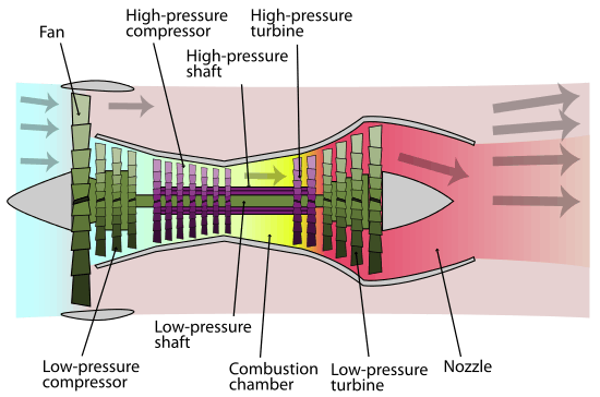
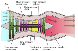
High-bypass turbofan
- Low-pressure spool
- High-pressure spool
- Stationary components
- Nacelle
- Fan
- Low-pressure compressor
- High-pressure compressor
- Combustion chamber
- High-pressure turbine
- Low-pressure turbine
- Core nozzle
- Fan nozzle
To boost fuel economy and reduce noise, almost all of today's jet airliners and most military transport aircraft (e.g., the C-17) are powered by low-specific-thrust/high-bypass-ratio turbofans. These engines evolved from the high-specific-thrust/low-bypass-ratio turbofans used in such aircraft in the 1960s. (Modern combat aircraft tend to use low-bypass ratio turbofans, and some military transport aircraft use turboprops.)
Low specific thrust is achieved by replacing the multi-stage fan with a single-stage unit. Unlike some military engines, modern civil turbofans lack stationary inlet guide vanes in front of the fan rotor. The fan is scaled to achieve the desired net thrust.
The core (or gas generator) of the engine must generate enough power to drive the fan at its design flow and pressure ratio. Improvements in turbine cooling/material technology allow a higher (HP) turbine rotor inlet temperature, which allows a smaller (and lighter) core and (potentially) improving the core thermal efficiency. Reducing the core mass flow tends to increase the load on the LP turbine, so this unit may require additional stages to reduce the average stage loading and to maintain LP turbine efficiency. Reducing core flow also increases bypass ratio. Bypass ratios greater than 5:1 are increasingly common; the Pratt & Whitney PW1000G, which entered commercial service in 2016, attains 12.5:1.
Further improvements in core thermal efficiency can be achieved by raising the overall pressure ratio of the core. Improved blade aerodynamics reduces the number of extra compressor stages required. With multiple compressors (i.e., LPC, IPC, and HPC) dramatic increases in overall pressure ratio have become possible. Variable geometry (i.e., stators) enable high-pressure-ratio compressors to work surge-free at all throttle settings.

The first (experimental) high-bypass turbofan engine was built and run on February 13, 1964 by AVCO-Lycoming.[28][29] Shortly after, the General Electric TF39 became the first production model, designed to power the Lockheed C-5 Galaxy military transport aircraft.[14] The civil General Electric CF6 engine used a derived design. Other high-bypass turbofans are the Pratt & Whitney JT9D, the three-shaft Rolls-Royce RB211 and the CFM International CFM56; also the smaller TF34. More recent large high-bypass turbofans include the Pratt & Whitney PW4000, the three-shaft Rolls-Royce Trent, the General Electric GE90/GEnx and the GP7000, produced jointly by GE and P&W.
The lower the specific thrust of a turbofan, the lower the mean jet outlet velocity, which in turn translates into a high thrust lapse rate ( i.e. decreasing thrust with increasing flight speed). See technical discussion below, item 2. Consequently, an engine sized to propel an aircraft at high subsonic flight speed (e.g., Mach 0.83) generates a relatively high thrust at low flight speed, thus enhancing runway performance. Low specific thrust engines tend to have a high bypass ratio, but this is also a function of the temperature of the turbine system.
The turbofans on twin engined airliners are further more powerful to cope with losing one engine during take-off, which reduces the aircraft's net thrust by half. Modern twin engined airliners normally climb very steeply immediately after take-off. If one engine is lost, the climb-out is much shallower, but sufficient to clear obstacles in the flightpath.
The Soviet Union's engine technology was less advanced than the West's and its first wide-body aircraft, the Ilyushin Il-86, was powered by low-bypass engines. The Yakovlev Yak-42, a medium-range, rear-engined aircraft seating up to 120 passengers introduced in 1980 was the first Soviet aircraft to use high-bypass engines.
Turbofan configurations
Turbofan engines come in a variety of engine configurations. For a given engine cycle (i.e., same airflow, bypass ratio, fan pressure ratio, overall pressure ratio and HP turbine rotor inlet temperature), the choice of turbofan configuration has little impact upon the design point performance (e.g., net thrust, SFC), as long as overall component performance is maintained. Off-design performance and stability is, however, affected by engine configuration.
As the design overall pressure ratio of an engine cycle increases, it becomes more difficult to operate at low rpm, without encountering an instability known as compressor surge. This occurs when some of the compressor aerofoils stall (like the wings of an aircraft) causing a violent change in the direction of the airflow. However, compressor stall can be avoided, at low rpm, by progressively:
- opening interstage/intercompressor blow-off valves (inefficient), and/or
- closing variable stators within the compressor
Most modern western civil turbofans employ a relatively high-pressure-ratio high-pressure (HP) compressor, with many rows of variable stators to control surge margin at low rpm. In the three-spool RB211/Trent the core compression system is split into two, with the IP compressor, which supercharges the HP compressor, being on a different coaxial shaft and driven by a separate (IP) turbine. As the HP compressor has a modest pressure ratio its speed can be reduced surge-free, without employing variable geometry. However, because a shallow IP compressor working line is inevitable, the IPC has one stage of variable geometry on all variants except the -535, which has none.[30]
Single-shaft turbofan
Although far from common, the single-shaft turbofan is probably the simplest configuration, comprising a fan and high-pressure compressor driven by a single turbine unit, all on the same shaft. The SNECMA M53, which powers Dassault Mirage 2000 fighter aircraft, is an example of a single-shaft turbofan. Despite the simplicity of the turbomachinery configuration, the M53 requires a variable area mixer to facilitate part-throttle operation.
Aft-fan turbofan
One of the earliest turbofans was a derivative of the General Electric J79 turbojet, known as the CJ805-23, which featured an integrated aft fan/low-pressure (LP) turbine unit located in the turbojet exhaust jetpipe. Hot gas from the turbojet turbine exhaust expanded through the LP turbine, the fan blades being a radial extension of the turbine blades. This aft-fan configuration was later exploited in the General Electric GE-36 UDF (propfan) demonstrator of the early 80s. One of the problems with the aft fan configuration is hot gas leakage from the LP turbine to the fan.
Basic two-spool
Many turbofans have the basic two-spool configuration where both the fan and LP turbine (i.e., LP spool) are mounted on a second (LP) shaft, running concentrically with the HP spool (i.e., HP compressor driven by HP turbine). The Low Pressure spool runs at a lower radial velocity. The High Pressure spool turns more quickly and its compressor further compresses part of the air for combustion. The BR710 is typical of this configuration. At the smaller thrust sizes, instead of all-axial blading, the HP compressor configuration may be axial-centrifugal (e.g., General Electric CFE738), double-centrifugal or even diagonal/centrifugal (e.g., Pratt & Whitney Canada PW600).
Boosted two-spool
Higher overall pressure ratios can be achieved by either raising the HP compressor pressure ratio or adding an intermediate-pressure (IP) compressor between the fan and HP compressor, to supercharge or boost the latter unit helping to raise the overall pressure ratio of the engine cycle to the very high levels employed today (i.e., greater than 40:1, typically). All of the large American turbofans (e.g., General Electric CF6, GE90 and GEnx plus Pratt & Whitney JT9D and PW4000) feature an IP compressor mounted on the LP shaft and driven, like the fan, by the LP turbine, the mechanical speed of which is dictated by the tip speed and diameter of the fan. The Rolls-Royce BR715 is a non-American example of this. The high bypass ratios (i.e., fan duct flow/core flow) used in modern civil turbofans tends to reduce the relative diameter of the attached IP compressor, causing its mean tip speed to decrease. Consequently, more IPC stages are required to develop the necessary IPC pressure rise.
Three-spool
Rolls-Royce chose a three-spool configuration for their large civil turbofans (i.e., the RB211 and Trent families), where the intermediate pressure (IP) compressor is mounted on a separate (IP) shaft, running concentrically with the LP and HP shafts, and is driven by a separate IP turbine. The first three-spool engine was the earlier Rolls-Royce RB.203 Trent of 1967.
Ivchenko Design Bureau chose the same configuration for their Lotarev D-36 engine, followed by Lotarev/Progress D-18T and Progress D-436.
The Turbo-Union RB199 military turbofan also has a three-spool configuration, as do the military Kuznetsov NK-25 and NK-321.
Geared fan
As bypass ratio increases, the mean radius ratio of the fan and low-pressure turbine (LPT) increases. Consequently, if the fan is to rotate at its optimum blade speed the LPT blading will spin slowly, so additional LPT stages will be required, to extract sufficient energy to drive the fan. Introducing a (planetary) reduction gearbox, with a suitable gear ratio, between the LP shaft and the fan enables both the fan and LP turbine to operate at their optimum speeds. Typical of this configuration are the long-established Honeywell TFE731, the Honeywell ALF 502/507, and the recent Pratt & Whitney PW1000G.
Military turbofans

Most of the configurations discussed above are used in civilian turbofans, while modern military turbofans (e.g., SNECMA M88) are usually basic two-spool.
High-pressure turbine
Most civil turbofans use a high-efficiency, 2-stage HP turbine to drive the HP compressor. The CFM56 uses an alternative approach: a single-stage, high-work unit. While this approach is probably less efficient, there are savings on cooling air, weight and cost.
In the RB211 and Trent 3-spool engine series, the HP compressor pressure ratio is modest so only a single HP stage is required. Rather than adding stage/s to the LP turbine to drive the higher pressure ratio IP (intermediate pressure) compressor, Rolls-Royce mounts it on a separate shaft and drives it with an IP turbine.
Because the HP compressor pressure ratio is modest, modern military turbofans tend to use a single-stage HP turbine.
Low-pressure turbine
Modern civil turbofans have multi-stage LP turbines (e.g., 3, 4, 5, 6, 7). The number of stages required depends on the engine cycle bypass ratio and how much supercharging (i.e., IP compression) is on the LP shaft, behind the fan. A geared fan may reduce the number of required LPT stages in some applications.[31] Because of the much lower bypass ratios employed, military turbofans require only one or two LP turbine stages.
Overall performance
Cycle improvements
Consider a mixed turbofan with a fixed bypass ratio and airflow. Increasing the overall pressure ratio of the compression system raises the combustor entry temperature. Therefore, at a fixed fuel flow there is an increase in (HP) turbine rotor inlet temperature. Although the higher temperature rise across the compression system implies a larger temperature drop over the turbine system, the mixed nozzle temperature is unaffected, because the same amount of heat is being added to the system. There is, however, a rise in nozzle pressure, because overall pressure ratio increases faster than the turbine expansion ratio, causing an increase in the hot mixer entry pressure. Consequently, net thrust increases, whilst specific fuel consumption (fuel flow/net thrust) decreases. A similar trend occurs with unmixed turbofans.
So turbofans can be made more fuel efficient by raising overall pressure ratio and turbine rotor inlet temperature in unison. However, better turbine materials and/or improved vane/blade cooling are required to cope with increases in both turbine rotor inlet temperature and compressor delivery temperature. Increasing the latter may require better compressor materials.
Overall pressure ratio can be increased by improving fan (or) LP compressor pressure ratio and/or HP compressor pressure ratio. If the latter is held constant, the increase in (HP) compressor delivery temperature (from raising overall pressure ratio) implies an increase in HP mechanical speed. However, stressing considerations might limit this parameter, implying, despite an increase in overall pressure ratio, a reduction in HP compressor pressure ratio.
According to simple theory, if the ratio of turbine rotor inlet temperature/(HP) compressor delivery temperature is maintained, the HP turbine throat area can be retained. However, this assumes that cycle improvements are obtained, while retaining the datum (HP) compressor exit flow function (non-dimensional flow). In practice, changes to the non-dimensional speed of the (HP) compressor and cooling bleed extraction would probably make this assumption invalid, making some adjustment to HP turbine throat area unavoidable. This means the HP turbine nozzle guide vanes would have to be different from the original. In all probability, the downstream LP turbine nozzle guide vanes would have to be changed anyway.
Thrust growth
Thrust growth is obtained by increasing core power. There are two basic routes available:
- hot route: increase HP turbine rotor inlet temperature
- cold route: increase core mass flow
Both routes require an increase in the combustor fuel flow and, therefore, the heat energy added to the core stream.
The hot route may require changes in turbine blade/vane materials and/or better blade/vane cooling. The cold route can be obtained by one of the following:
- adding T-stages to the LP/IP compression
- adding a zero-stage to the HP compression
- improving the compression process, without adding stages (e.g. higher fan hub pressure ratio)
all of which increase both overall pressure ratio and core airflow.
Alternatively, the core size can be increased, to raise core airflow, without changing overall pressure ratio. This route is expensive, since a new (upflowed) turbine system (and possibly a larger IP compressor) is also required.
Changes must also be made to the fan to absorb the extra core power. On a civil engine, jet noise considerations mean that any significant increase in take-off thrust must be accompanied by a corresponding increase in fan mass flow (to maintain a T/O specific thrust of about 30 lbf/lb/s).
Technical discussion
- Specific thrust (net thrust/intake airflow) is an important parameter for turbofans and jet engines in general. Imagine a fan (driven by an appropriately sized electric motor) operating within a pipe, which is connected to a propelling nozzle. It is fairly obvious, the higher the fan pressure ratio (fan discharge pressure/fan inlet pressure), the higher the jet velocity and the corresponding specific thrust. Now imagine we replace this set-up with an equivalent turbofan – same airflow and same fan pressure ratio. Obviously, the core of the turbofan must produce sufficient power to drive the fan via the low-pressure (LP) turbine. If we choose a low (HP) turbine inlet temperature for the gas generator, the core airflow needs to be relatively high to compensate. The corresponding bypass ratio is therefore relatively low. If we raise the turbine inlet temperature, the core airflow can be smaller, thus increasing bypass ratio. Raising turbine inlet temperature tends to increase thermal efficiency and, therefore, improve fuel efficiency.
- Naturally, as altitude increases, there is a decrease in air density and, therefore, the net thrust of an engine. There is also a flight speed effect, termed thrust lapse rate. Consider the approximate equation for net thrust again:
With a high specific thrust (e.g., fighter) engine, the jet velocity is relatively high, so intuitively one can see that increases in flight velocity have less of an impact upon net thrust than a medium specific thrust (e.g., trainer) engine, where the jet velocity is lower. The impact of thrust lapse rate upon a low specific thrust (e.g., civil) engine is even more severe. At high flight speeds, high-specific-thrust engines can pick up net thrust through the ram rise in the intake, but this effect tends to diminish at supersonic speeds because of shock wave losses. - Thrust growth on civil turbofans is usually obtained by increasing fan airflow, thus preventing the jet noise becoming too high. However, the larger fan airflow requires more power from the core. This can be achieved by raising the overall pressure ratio (combustor inlet pressure/intake delivery pressure) to induce more airflow into the core and by increasing turbine inlet temperature. Together, these parameters tend to increase core thermal efficiency and improve fuel efficiency.
- Some high-bypass-ratio civil turbofans use an extremely low area ratio (less than 1.01), convergent-divergent, nozzle on the bypass (or mixed exhaust) stream, to control the fan working line. The nozzle acts as if it has variable geometry. At low flight speeds the nozzle is unchoked (less than a Mach number of unity), so the exhaust gas speeds up as it approaches the throat and then slows down slightly as it reaches the divergent section. Consequently, the nozzle exit area controls the fan match and, being larger than the throat, pulls the fan working line slightly away from surge. At higher flight speeds, the ram rise in the intake increases nozzle pressure ratio to the point where the throat becomes choked (M=1.0). Under these circumstances, the throat area dictates the fan match and, being smaller than the exit, pushes the fan working line slightly towards surge. This is not a problem, since fan surge margin is much better at high flight speeds.
- The off-design behaviour of turbofans is illustrated under compressor map and turbine map.
- Because modern civil turbofans operate at low specific thrust, they require only a single fan stage to develop the required fan pressure ratio. The desired overall pressure ratio for the engine cycle is usually achieved by multiple axial stages on the core compression. Rolls-Royce tend to split the core compression into two with an intermediate pressure (IP) supercharging the HP compressor, both units being driven by turbines with a single stage, mounted on separate shafts. Consequently, the HP compressor need develop only a modest pressure ratio (e.g., ~4.5:1). US civil engines use much higher HP compressor pressure ratios (e.g., ~23:1 on the General Electric GE90) and tend to be driven by a two-stage HP turbine. Even so, there are usually a few IP axial stages mounted on the LP shaft, behind the fan, to further supercharge the core compression system. Civil engines have multi-stage LP turbines, the number of stages being determined by the bypass ratio, the amount of IP compression on the LP shaft and the LP turbine blade speed.
- Because military engines usually have to be able to fly very fast at sea level, the limit on HP compressor delivery temperature is reached at a fairly modest design overall pressure ratio, compared with that of a civil engine. Also the fan pressure ratio is relatively high, to achieve a medium to high specific thrust. Consequently, modern military turbofans usually have only 5 or 6 HP compressor stages and require only a single-stage HP turbine. Low-bypass-ratio military turbofans usually have one LP turbine stage, but higher bypass ratio engines need two stages. In theory, by adding IP compressor stages, a modern military turbofan HP compressor could be used in a civil turbofan derivative, but the core would tend to be too small for high thrust applications.

Early turbofans
_used_in_Boeing_707-420_at_Flugausstellung_Hermeskeil%2C_pic1.JPG)
Early turbojet engines were not very fuel-efficient as their overall pressure ratio and turbine inlet temperature were severely limited by the technology available at the time. The first turbofan to run was the German Daimler-Benz DB 670 (designated as the 109-007 by the RLM) with a first run date of 27 May 1943. Turbomachinery testing, using an electric motor, had started on 1 April 1943.[32] The engine was abandoned later while the war went on and problems could not be solved. The British wartime Metrovick F.2 axial flow jet was given a fan, as the Metrovick F.3 in 1943, to create the first British turbofan.[33]
Improved materials, and the introduction of twin compressors such as in the Bristol Olympus[34] and Pratt & Whitney JT3C engines, increased the overall pressure ratio and thus the thermodynamic efficiency of engines, but they also led to a poor propulsive efficiency, as pure turbojets have a high specific thrust/high velocity exhaust better suited to supersonic flight.
The original low-bypass turbofan engines were designed to improve propulsive efficiency by reducing the exhaust velocity to a value closer to that of the aircraft. The Rolls-Royce Conway, the world's first production turbofan, had a bypass ratio of 0.3, similar to the modern General Electric F404 fighter engine. Civilian turbofan engines of the 1960s, such as the Pratt & Whitney JT8D and the Rolls-Royce Spey had bypass ratios closer to 1, and were similar to their military equivalents.
The first General Electric turbofan was the aft-fan CJ805-23 based on the CJ805-3 turbojet. It was followed by the aft-fan General Electric CF700 engine with a 2.0 bypass ratio. This was derived from the General Electric J85/CJ610 turbojet (2,850 lbf or 12,650 N) to power the larger Rockwell Sabreliner 75/80 model aircraft, as well as the Dassault Falcon 20 with about a 50% increase in thrust (4,200 lbf or 18,700 N). The CF700 was the first small turbofan in the world to be certified by the Federal Aviation Administration (FAA). There were at one time over 400 CF700 aircraft in operation around the world, with an experience base of over 10 million service hours. The CF700 turbofan engine was also used to train Moon-bound astronauts in Project Apollo as the powerplant for the Lunar Landing Research Vehicle.
Recent developments
Aerodynamic modelling
Aerodynamics is a mix of subsonic, transonic and supersonic airflow on a single fan/gas compressor blade in a modern turbofan. The airflow past the blades has to be maintained within close angular limits to keep the air flowing against an increasing pressure. Otherwise the air will come back out of the intake.[35]
The Full Authority Digital Engine Control (FADEC) needs accurate data for controlling the engine. The critical turbine inlet temperature (TIT) is too harsh an environment, at 1,700 °C and 17 bars, for reliable sensors. During development of a new engine type a relation is established between a more easily measured temperature like Exhaust gas temperature and the TIT. The EGT is then used to make sure the engine doesn't run too hot.[35]
Blade technology
A 100 g turbine blade is subjected to 1,700 °C/3100 °F, at 17 bars/250 Psi and a centrifugal force of 40 kN/ 9,000 lbf, well above the point of plastic deformation and even above the melting point. Exotic alloys, sophisticated air cooling schemes and special mechanical design are needed to keep the physical stresses within the strength of the material. Rotating seals must withstand harsh conditions for 10 years, 20,000 missions and rotating at 10–20,000 rpm.[35]
The high-temperature performance of fan blades has increased through developments in the casting manufacturing process, the cooling design, thermal barrier coatings, and alloys. Cycle-wise, the HP turbine inlet temperature is less important than its rotor inlet temperature (RIT), after the temperature drop across its stator. Although modern engines have peak RITs of the order of 1,560 °C (2,840 °F), such temperatures are experienced only for a short time during take-off on civil engines.
Originally standard polycrystalline metals were used to make fan blades, but developments in material science have allowed blades to be constructed from aligned metallic crystals and more recently single crystals to operate at higher temperatures with less distortion. These alloys and Nickel-based superalloys are utilized in HP turbine blades in most modern jet engines.
HP turbine inlet is cooled below its melting point with air bled from the compressor, bypassing the combustor and entering the hollow blade or vane.[36] After picking up heat, the cooling air is dumped into the main gas stream and downstream stages are uncooled if the local temperatures are low enough.
Fan blades
Fan blades have been growing as jet engines have been getting bigger: each fan blade carries the equivalent of nine double-decker buses and swallows the volume of a squash court every second. Advances in computational fluid dynamics (CFD) modelling have permitted complex, 3D curved shapes with very wide chord, keeping the fan capabilities while minimizing the blade count to lower costs. Coincidentally, the bypass ratio grew to achieve higher propulsive efficiency and the fan diameter increased.[37]
Rolls-Royce pioneered the hollow, titanium wide-chord fan blade in the 1980s for aerodynamic efficiency and foreign object damage resistance in the RB211 then for the Trent. GE Aviation introduced carbon fiber composite fan blades on the GE90 in 1995, manufactured today with a carbon-fiber tape-layer process. GE partner Safran developed a 3D woven technology with Albany Composites for the CFM56 and CFM LEAP engines.[37]
Future progress
Engine cores are shrinking as they are operating at higher pressure ratios and becoming more efficient, and become smaller compared to the fan as bypass ratios increase. Blade tip clearances are harder to maintain at the exit of the high-pressure compressor where blades are 0.5 in (13 mm) high or less, backbone bending further affects clearance control as the core is proportionately longer and thinner and the fan to low-pressure turbine driveshaft is in constrained space within the core.[38]
For Pratt & Whitney VP technology and environment Alan Epstein "Over the history of commercial aviation, we have gone from 20% to 40% [cruise efficiency], and there is a consensus among the engine community that we can probably get to 60%".[39]
Geared turbofans and further fan pressure ratio reductions will continue to improve propulsive efficiency. The second phase of the FAA’s Continuous Lower Energy, Emissions and Noise (CLEEN) program is targeting for the late 2020s reductions of 33% fuel burn, 60% emissions and 32 dB EPNdb noise compared with the 2000s state-of-the-art. In summer 2017 at NASA Glenn Research Center in Cleveland, Ohio, Pratt has finished testing a very-low-pressure-ratio fan on a PW1000G, resembling an open rotor with less blades than the PW1000G's 20.[39]
The weight and size of the nacelle would be reduced by a short duct inlet, imposing higher aerodynamic turning loads on the blades and leaving less space for soundproofing, but a lower-pressure-ratio fan is slower. UTC Aerospace Systems Aerostructures will have a full-scale ground test in 2019 of its low-drag Integrated Propulsion System with a thrust reverser, improving fuel burn by 1% and with 2.5-3 EPNdB lower noise.[39]
Safran can probably deliver another 10–15% in fuel efficiency through the mid-2020s before reaching an asymptote, and next will have to introduce a breakthrough : to increase the bypass ratio to 35:1 instead of 11:1 for the CFM LEAP, it is demonstrating a counterrotating open rotor unducted fan (propfan) in Istres, France, under the European Clean Sky technology program. Modeling advances and high specific strength materials may help it succeed where previous attempts failed. When noise levels will be within current standards and similar to the Leap engine, 15% lower fuel burn will be available and for that Safran is testing its controls, vibration and operation, while airframe integration is still challenging.[39]
For GE Aviation, the energy density of jet fuel still maximises the Breguet range equation and higher pressure ratio cores, lower pressure ratio fans, low-loss inlets and lighter structures can further improve thermal, transfer and propulsive efficiency. Under the U.S. Air Force’s Adaptive Engine Transition Program, adaptive thermodynamic cycles will be used for the sixth-generation jet fighter, based on a modified Brayton cycle and Constant volume combustion. Additive manufacturing in the advanced turboprop will reduce weight by 5% and fuel burn by 20%.[39]
Rotating and static ceramic matrix composite (CMC) parts operates 500 °F (260 °C) hotter than metal and are one-third its weight. With $21.9 million from the Air Force Research Laboratory, GE is investing $200 million in a CMC facility in Huntsville, Alabama, in addition to its Asheville, North Carolina site, mass-producing silicon carbide matrix with silicon-carbide fibers in 2018. CMCs will be used ten times more by the mid-2020s : the CFM LEAP requires 18 CMC turbine shrouds per engine and the GE9X will use it in the combustor and for 42 HP turbine nozzles.[39]
Rolls-Royce Plc aim for a 60:1 pressure ratio core for the 2020s Ultrafan and began ground tests of its 100,000 hp (75,000 kW) gear for 100,000 lbf (440 kN) and 15:1 bypass ratios. Nearly stoichiometric turbine entry temperatures approaches the theoretical limit and its impact on emissions has to be balanced with environmental performance goals. Open rotors, lower pressure ratio fans and potentially distributed propulsion offers more room for better propulsive efficiency. Exotic cycles, heat exchangers and pressure gain/constant volume combustion can improve thermodynamic efficiency. Additive manufacturing could be an enabler for intercooler and recuperators. Closer airframe integration and hybrid or electric aircraft can be combined with gas turbines.[39]
Current Rolls-Royce engines have a 72–82% propulsive efficiency and 42–49% thermal efficiency for a 0.63–0.49 lb/lbf/h (64,000–50,000 g/kN/h) TSFC at Mach 0.8, and aim for theoretical limits of 95% for open rotor propulsive efficiency and 60% for thermal efficiency with stoichiometric turbine entry temperature and 80:1 overall pressure ratio for a 0.35 lb/lbf/h (36,000 g/kN/h) TSFC[40]
As teething troubles may not show up until several thousand hours, the latest turbofans technical problems disrupt airlines operations and manufacturers deliveries while production rates are rising sharply. Trent 1000 cracked blades grounded almost 50 Boeing 787s and reduced ETOPS to 2.3 hours down from 5.5, costing Rolls-Royce plc almost $950 million. PW1000G knife-edge seal fractures have caused Pratt & Whitney to fall way behind in deliveries, leaving about 100 engineless A320neos waiting for their powerplants. The CFM LEAP introduction was smoother but a ceramic composite HP Turbine coating is prematurely lost, necessitating a new design, causing 60 A320neo engine removal for modification, as deliveries are up to six weeks late.[41]
Manufacturers
The turbofan engine market is dominated by General Electric, Rolls-Royce plc and Pratt & Whitney, in order of market share. General Electric and SNECMA of France have a joint venture, CFM International. Pratt & Whitney also have a joint venture, International Aero Engines with Japanese Aero Engine Corporation and MTU Aero Engines of Germany, specializing in engines for the Airbus A320 family. Pratt & Whitney and General Electric have a joint venture, Engine Alliance selling a range of engines for aircraft such as the Airbus A380.
For airliners and cargo aircraft, the in-service fleet in 2016 is 60,000 engines and should grow to 103,000 in 2035 with 86,500 deliveries according to Flight Global. A majority will be medium-thrust engines for narrow-body aircraft with 54,000 deliveries, for a fleet growing from 28,500 to 61,000. High-thrust engines for wide-body aircraft, worth 40–45% of the market by value, will grow from 12,700 engines to over 21,000 with 18,500 deliveries. The regional jet engines below 20,000 lb (89 kN) fleet will grow from 7,500 to 9,000 and the fleet of turboprops for airliners will increase from 9,400 to 10,200. The manufacturers market share should be led by CFM with 44% followed by Pratt & Whitney with 29% and then Rolls-Royce and General Electric with 10% each.[42]
Gallery
 Soloviev D-30 which powers the Mikoyan MiG-31, Ilyushin Il-76, Ilyushin Il-62M, Xian H-6K, Xian Y-20
 PowerJet SaM146 which powers Sukhoi Superjet 100
 Rolls-Royce Trent 900 undergoing climatic testing
.jpg) Pratt & Whitney PW4000 which powered the first Boeing 777
Pratt & Whitney PW4000 which powered the first Boeing 777
 Engine Alliance GP7000 turbofan for the Airbus A380


_(524-34).jpg) Aviadvigatel PD-14 which will be used on the Irkut MC-21
Aviadvigatel PD-14 which will be used on the Irkut MC-21 Ivchenko-Progress D-436 sharing the three shaft principle with Rolls-Royce Trent
.jpg) NPO Saturn AL-55 which powers certain HAL HJT-36 Sitara
NPO Saturn AL-55 which powers certain HAL HJT-36 Sitara Eurojet EJ200 which powers the Eurofighter Typhoon
 Ishikawajima-Harima F3 which powers the Kawasaki T-4
Commercial turbofans in production
| Model | Start | Bypass | Length | Fan | Weight | Thrust | Major applications |
|---|---|---|---|---|---|---|---|
| GE GE90 | 1992 | 8.7–9.9 | 5.18m–5.40m | 3.12–3.25 m | 7.56–8.62t | 330–510 kN | B777 |
| P&W PW4000 | 1984 | 4.8–6.4 | 3.37–4.95m | 2.84 m | 4.18–7.48t | 222–436 kN | A300/A310, A330, B747, B767, B777, MD-11 |
| R-R Trent XWB | 2010 | 9.3 | 5.22 m | 3.00 m | 7.28 t | 330–430 kN | A350XWB |
| R-R Trent 800 | 1993 | 5.7–5.79 | 4.37m | 2.79m | 5.96–5.98t | 411–425 kN | B777 |
| EA GP7000 | 2004 | 8.7 | 4.75 m | 2.95 m | 6.09–6.71 t | 311–363 kN | A380 |
| R-R Trent 900 | 2004 | 8.7 | 4.55 m | 2.95 m | 6.18–6.25 t | 340–357 kN | A380 |
| R-R Trent 1000 | 2006 | 10.8–11 | 4.74 m | 2.85 m | 5.77 t | 265.3–360.4 kN | B787 |
| GE GEnx[44] | 2006 | 8.0–9.3 | 4.31-4.69 m | 2.66-2.82 m | 5.62-5.82 t | 296-339 kN | B747-8, B787 |
| R-R Trent 700 | 1990 | 4.9 | 3.91 m | 2.47 m | 4.79 t | 320 kN | A330 |
| GE CF6 | 1971 | 4.3–5.3 | 4.00–4.41 m | 2.20–2.79 m | 3.82–5.08 t | 222–298 kN | A300/A310, A330, B747, B767, MD-11, DC-10 |
| R-R Trent 500 | 1999 | 8.5 | 3.91 m | 2.47 m | 4.72 t | 252 kN | A340-500/600 |
| P&W PW1000G[45] | 2008 | 9.0–12.5 | 3.40 m | 1.42–2.06 m | 2.86 t | 67–160 kN | A320neo, A220, E-Jets E2 |
| CFM LEAP[46] | 2013 | 9.0–11.0 | 3.15–3.33m | 1.76–1.98m | 2.78–3.15t | 100–146 kN | A320neo, B737Max |
| CFM56 | 1974 | 5.0–6.6 | 2.36–2.52m | 1.52–1.84m | 1.95–2.64t | 97.9-151 kN | A320, A340-200/300, B737, KC-135, DC-8 |
| IAE V2500 | 1987 | 4.4–4.9 | 3.20m | 1.60m | 2.36–2.54t | 97.9-147 kN | A320, MD-90 |
| P&W PW6000 | 2000 | 4.90 | 2.73m | 1.44m | 2.36t | 100.2 kN | Airbus A318 |
| R-R BR700 | 1994 | 4.2–4.5 | 3.41–3.60m | 1.32–1.58m | 1.63–2.11t | 68.9–102.3 kN | B717, Global Express, Gulfstream V |
| GE Passport | 2013 | 5.6 | 3.37m | 1.30m | 2.07t | 78.9–84.2 kN | Global 7000/8000 |
| GE CF34 | 1982 | 5.3–6.3 | 2.62–3.26m | 1.25–1.32m | 0.74–1.12t | 41–82.3 kN | Challenger 600, CRJ, E-jets |
| P&WC PW800 | 2012 | 5.5 | 1.30m | 67.4–69.7 kN | Gulfstream G500/G600 | ||
| R-R Tay | 1984 | 3.1–3.2 | 2.41m | 1.12–1.14m | 1.42–1.53t | 61.6–68.5 kN | Gulfstream IV, Fokker 70/100 |
| Silvercrest | 2012 | 5.9 | 1.90m | 1.08m | 1.09t | 50.9 kN | Cit. Hemisphere, Falcon 5X |
| R-R AE 3007 | 1991 | 5.0 | 2.71m | 1.11m | 0.72t | 33,7 kN | ERJ, Citation X |
| P&WC PW300 | 1988 | 3.8–4.5 | 1.92–2.07 | 0.97m | 0.45–0.47t | 23.4–35.6 kN | Cit. Sovereign, G200, F. 7X, F. 2000 |
| HW HTF7000 | 1999 | 4.4 | 2.29m | 0.87m | 0.62t | 28.9 kN | Challenger 300, G280, Legacy 500 |
| HW TFE731 | 1970 | 2.66–3.9 | 1.52–2.08m | .072-0.78m | 0.34–0.45t | 15.6–22.2 kN | Learjet 70/75, G150, Falcon 900 |
| Williams FJ44 | 1985 | 3.3–4.1 | 1.36–2.09m | .53-0.57m | 0.21–0.24t | 6.7–15.6 kN | CitationJet, Cit. M2 |
| P&WC PW500 | 1993 | 3.90 | 1.52m | 0.70m | 0.28t | 13.3 kN | Citation Excel, Phenom 300 |
| GE-H HF120 | 2009 | 4.43 | 1.12m | 0.54 m | 0.18t | 7.4 kN | HondaJet |
| Williams FJ33 | 1998 | 0.98m | 0.53 m | 0.14 t | 6.7 kN | Cirrus SF50 | |
| P&WC PW600 | 2001 | 1.8–2.8 | 0.67m | 0.36m | 0.15t | 6.0 kN | Cit. Mustang, Eclipse 500, Phenom 100 |
| PS-90 | 1992 | 4.4 | 4.96m | 1.9m | 2.95t | 157–171 kN | Ilyushin Il-76, Ilyushin Il-96, Tupolev Tu-204 |
| PowerJet SaM146 | 2008 | 4-4.1 | 3.59m | 1.22m | 2.260t | 71.6–79.2 kN | Sukhoi Superjet 100 |
Extreme bypass jet engines
In the 1970s, Rolls-Royce/SNECMA tested a M45SD-02 turbofan fitted with variable pitch fan blades to improve handling at ultra low fan pressure ratios and to provide thrust reverse down to zero aircraft speed. The engine was aimed at ultra quiet STOL aircraft operating from city centre airports.
In a bid for increased efficiency with speed, a development of the turbofan and turboprop known as a propfan engine was created that had an unducted fan. The fan blades are situated outside of the duct, so that it appears like a turboprop with wide scimitar-like blades. Both General Electric and Pratt & Whitney/Allison demonstrated propfan engines in the 1980s. Excessive cabin noise and relatively cheap jet fuel prevented the engines being put into service. The Progress D-27 propfan, developed in the U.S.S.R., was the only propfan engine equipped on a production aircraft.
Terminology
- Afterburner
- extra combustor immediately upstream of final nozzle (also called reheat)
- Augmentor
- afterburner on low-bypass turbofan engines.
- Average stage loading
- constant × (delta temperature)/[(blade speed) × (blade speed) × (number of stages)]
- Bypass
- airstream that completely bypasses the core compression system, combustor and turbine system
- Bypass ratio
- bypass airflow /core compression inlet airflow
- Core
- turbomachinery handling the airstream that passes through the combustor.
- Core power
- residual shaft power from ideal turbine expansion to ambient pressure after deducting core compression power
- Core thermal efficiency
- core power/power equivalent of fuel flow
- Dry
- afterburner (if fitted) not lit
- EGT
- exhaust gas temperature
- EPR
- engine pressure ratio
- Fan
- turbofan LP compressor
- Fan pressure ratio
- fan outlet total pressure/intake delivery total pressure
- Flex temp
- use of artificially high apparent air temperature to reduce engine wear
- Gas generator
- engine core
- HP compressor
- high-pressure compressor (also HPC)
- HP turbine
- high-pressure turbine
- Intake ram drag
- penalty associated with jet engines picking up air from the atmosphere (conventional rocket motors do not have this drag term, because the oxidiser travels with the vehicle)
- IEPR
- integrated engine pressure ratio
- IP compressor
- intermediate pressure compressor (also IPC)
- IP turbine
- intermediate pressure turbine (also IPT)
- LP compressor
- low-pressure compressor (also LPC)
- LP turbine
- low-pressure turbine (also LPT)
- Net thrust
- nozzle total gross thrust – intake ram drag (excluding nacelle drag, etc., this is the basic thrust acting on the airframe)
- Overall pressure ratio
- combustor inlet total pressure/intake delivery total pressure
- Overall efficiency
- thermal efficiency * propulsive efficiency
- Propulsive efficiency
- propulsive power/rate of production of propulsive kinetic energy (maximum propulsive efficiency occurs when jet velocity equals flight velocity, which implies zero net thrust!)
- Specific fuel consumption (SFC)
- total fuel flow/net thrust (proportional to flight velocity/overall thermal efficiency)
- Spooling up
- accelerating, marked by a delay
- Static pressure
- pressure of the fluid which is associated not with its motion but with its state[47]
- Specific thrust
- net thrust/intake airflow
- Thermal efficiency
- rate of production of propulsive kinetic energy/fuel power
- Total fuel flow
- combustor (plus any afterburner) fuel flow rate (e.g., lb/s or g/s)
- Total pressure
- static pressure plus kinetic energy term
- Turbine rotor inlet temperature
- gas absolute mean temperature at principal (e.g., HP) turbine rotor entry
See also
References
- ↑ Marshall Brain. "How Gas Turbine Engines Work". howstuffworks.com. Retrieved 2010-11-24.
- ↑ Hall, Nancy (May 5, 2015). "Turbofan Engine". Glenn Research Center. NASA. Retrieved October 25, 2015.
Most modern airliners use turbofan engines because of their high thrust and good fuel efficiency.
- 1 2 Michael Hacker; David Burghardt; Linnea Fletcher; Anthony Gordon; William Peruzzi (March 18, 2009). Engineering and Technology. Cengage Learning. p. 319. ISBN 978-1-285-95643-5. Retrieved October 25, 2015.
All modern jet-powered commercial aircraft use high bypass turbofan engines [...]
- 1 2 Bharat Verma (January 1, 2013). Indian Defence Review: Apr–Jun 2012. Lancer Publishers. p. 18. ISBN 978-81-7062-259-8. Retrieved October 25, 2015.
Military power plants may be divided into some major categories – low bypass turbofans that generally power fighter jets [...]
- ↑ Frank Northen Magill, ed. (1993). Magill's Survey of Science: Applied science series, Volume 3. Salem Press. p. 1431. ISBN 9780893567088.
Most tactical military aircraft are powered by low-bypass turbofan engines.
- ↑ Hall, Nancy (May 5, 2015). "Turbofan Engine". Glenn Research Center. NASA. Retrieved October 25, 2015.
Most modern airliners use turbofan engines because of their high thrust and good fuel efficiency.
- ↑ Frank Northen Magill, ed. (1993). Magill's Survey of Science: Applied science series, Volume 3. Salem Press. p. 1431. ISBN 9780893567088.
Most tactical military aircraft are powered by low-bypass turbofan engines.
- ↑ https://www.britannica.com/technology/bypass-ratio
- ↑ https://www.flightglobal.com/pdfarchive/view/1964/1964%20-%202596.html
- ↑ Jane's All The World's Aircraft 1975-1976, edited by John W.R. Taylor, Jane's Yearbooks, Paulton House, 8 Sheperdess Walk, London N1 7LW, p.748
- ↑ http://proceedings.asmedigitalcollection.asme.org/proceeding.aspx?articleid=2275853
- ↑ http://roadrunnersinternationale.com/pw_tales.htm
- ↑ "Turbofan Engine". www.grc.nasa.gov. Retrieved 2010-11-24.
- 1 2 Neumann, Gerhard (2004) [1984], Herman the German: Just Lucky I Guess, Bloomington, IN, USA: Authorhouse, ISBN 1-4184-7925-X. First published by Morrow in 1984 as Herman the German: Enemy Alien U.S. Army Master Sergeant. Republished with a new title in 2004 by Authorhouse, with minor or no changes. , pp. 228–230.
- ↑ "The turbofan engine Archived 2015-04-18 at the Wayback Machine.", page 7. SRM University, Department of aerospace engineering
- ↑ Gas Turbine Theory Second Edition, Cohen, Rogers and Saravanamuttoo, Longmans Group Limited 1972, ISBN 0 582 44927 8, p.85
- ↑ Federal Aviation Administration (FAA) (2004). FAA-H-8083-3B Airplane Flying Handbook Handbook (PDF). Federal Aviation Administration. Archived from the original (PDF) on 2012-09-21.
- ↑ "Turbofan Thrust".
- ↑ https://dspace.lib.cranfield.ac.uk/bitstream/handle/1826/12476/Civil_turbofan_engine_exhaust_aerodynamics-2017.pdf
- ↑ "Softtly, softly towards the quiet jet" Michael J.T.Smith, New Scientist, 19 February 1970, Figure 5
- ↑ Kempton, A, "Acoustic liners for modern aero-engines", 15th CEAS-ASC Workshop and 1st Scientific Workshop of X-Noise EV, 2011.
- ↑ A. McAlpine "Research project: Buzz-saw noise and nonlinear acoustics"
- ↑ Schuster, B., Lieber, L., & Vavalle, A., Optimization of a seamless inlet liner using an empirically validated prediction method. In 16th AIAA/CEAS Aeroacoustics Conference, Stockholm, Sweden.
- ↑ Ferrante, P. G., Copiello, D., & Beutke, M.. Design and experimental verification of “true zero-splice” acoustic liners in the universal fan facility adaptation (UFFA) modular rig,”. In 17h AIAA/CEAS Aeroacoustics Conference, AIAA-2011-2728, Portland, OR.
- 1 2 3 Banke, Jim (2012-12-13). "NASA Helps Create a More Silent Night". NASA. Retrieved January 12, 2013.
- ↑ Zaman, K.B.M.Q.; Bridges, J. E.; Huff, D. L. (17–21 December 2010). "Evolution from 'Tabs' to 'Chevron Technology'–a Review" (PDF-1.34 Mb). Proceedings of the 13th Asian Congress of Fluid Mechanics 17–21 December 2010, Dhaka, Bangladesh. NASA Glenn Research Center. Cleveland, Ohio. Retrieved January 29, 2013.
- ↑ https://web.archive.org/web/20140325205124/http://www.afmc.org.cn/13thacfm/invited/201.pdf
- ↑ Decher, S., Rauch, D., “Potential of the High Bypass Turbofan,” American Society of Mechanical Engineers paper 64-GTP-15, presented at the Gas Turbine Conference and Products Show, Houston, Texas, March 1–5, 1964.
- ↑ US Patent 3,390,527, High Bypass Ratio Turbofan, July 2, 1968.
- ↑ RB211-535E4
- ↑ ""The geared turbofan technology – Opportunities, challenges and readiness status"" (PDF). Archived from the original on 2013-05-20. C. Riegler, C. Bichlmaier:, 1st CEAS European Air and Space Conference, 10–13 September 2007, Berlin, Germany
- ↑ "Turbojet History And Development 1930–1960 Volume 1", The Crowood Press Ltd. 2007, ISBN 978 1 86126 912 6, p.241
- ↑ "Metrovick F3 Cutaway – Pictures & Photos on FlightGlobal Airspace". Flightglobal.com. 2007-11-07. Retrieved 2013-04-29.
- ↑ "1954 | 0985 | Flight Archive". Flightglobal.com. 1954-04-09. Retrieved 2013-04-29.
- 1 2 3 Bjorn Fehrm (October 21, 2016). "Bjorn's Corner: The Engine challenge". Leeham News.
- ↑ Peter Spittle, Rolls-Royce plc (November 2003). "Gas turbine technology" (PDF). Physics Education.
- 1 2 Ben Hargreaves (Sep 28, 2017). "Understanding Complexities Of Bigger Fan Blades". Aviation Week Network.
- ↑ Guy Norris and Graham Warwick (Mar 26, 2015). "A Reversed, Tilted Future For Pratt's Geared Turbofan?". Aviation Week & Space Technology.
- 1 2 3 4 5 6 7 Guy Norris (Aug 8, 2017). "Turbofans Are Not Finished Yet". Aviation Week & Space Technology.
- ↑ Ulrich Wenger (March 20, 2014), Rolls-Royce technology for future aircraft engines (PDF), Rolls-Royce Deutschland
- ↑ Dominic Gates (June 15, 2018). "Troublesome advanced engines for Boeing, Airbus jets have disrupted airlines and shaken travelers". The Seattle Times.
- ↑ "Flight Fleet Forecast's engine outlook". Flight Global. 2 November 2016.
- ↑ Jane's All the World's Aircraft. 2005. pp. 850–853. ISSN 0075-3017.
- ↑ "GEnx". GE.
- ↑ "PW1000G". MTU.
- ↑ "The Leap Engine". CFM International.
- ↑ Clancy, L.J., Aerodynamics, page 21
External links
| Wikimedia Commons has media related to Turbofan engines. |
- Wikibooks: Jet propulsion
- Malcolm Gibson (Aug 2011). "The Chevron Nozzle: A Novel Approach to Reducing Jet Noise" (PDF). NASA Innovation in Aeronautics NASA/TM-2011-216987.
- "The Engine Yearbook". UBM Aviation. 2012.
- "Commercial engines 2017". Flight Global.
- Bjorn Fehrm (April 14, 2017). "Bjorn's Corner: Aircraft engines, sum up". Leeham Co. and previous series