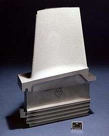
Turbine blade
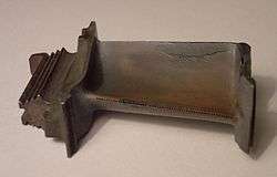
A turbine blade is the individual component which makes up the turbine section of a gas turbine or steam turbine. The blades are responsible for extracting energy from the high temperature, high pressure gas produced by the combustor. The turbine blades are often the limiting component of gas turbines.[1] To survive in this difficult environment, turbine blades often use exotic materials like superalloys and many different methods of cooling, such as internal air channels, boundary layer cooling, and thermal barrier coatings. Blade fatigue is a major source of failure in steam turbines and gas turbines. Fatigue is caused by the stress induced by vibration and resonance within the operating range of machinery. To protect blades from these high dynamic stresses, friction dampers are used.[2]
Blades of wind turbines and water turbines are designed to operate in different conditions, which typically involve lower rotational speeds and temperatures.
Introduction
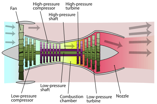
In a gas turbine engine, a single turbine section is made up of a disk or hub that holds many turbine blades. That turbine section is connected to a compressor section via a shaft (or "spool"), and that compressor section can either be axial or centrifugal. Air is compressed, raising the pressure and temperature, through the compressor stages of the engine. The temperature is then greatly increased by combustion of fuel inside the combustor, which sits between the compressor stages and the turbine stages. The high-temperature and high-pressure exhaust gases then pass through the turbine stages. The turbine stages extract energy from this flow, lowering the pressure and temperature of the air and transfer the kinetic energy to the compressor stages along the spool. This process is very similar to how an axial compressor works, only in reverse.[3]
The number of turbine stages varies in different types of engines, with high-bypass-ratio engines tending to have the most turbine stages. The number of turbine stages can have a great effect on how the turbine blades are designed for each stage. Many gas turbine engines are twin-spool designs, meaning that there is a high-pressure spool and a low-pressure spool. Other gas turbines use three spools, adding an intermediate-pressure spool between the high- and low-pressure spool. The high-pressure turbine is exposed to the hottest, highest-pressure air, and the low-pressure turbine is subjected to cooler, lower-pressure air. The difference in conditions leads to the design of high-pressure and low-pressure turbine blades that are significantly different in material and cooling choices even though the aerodynamic and thermodynamic principles are the same.[4] Under these severe operating conditions inside the gas and steam turbines, the blades face high temperature, high stresses, and potentially high vibrations. Steam turbine blades are critical components in power plants which convert the linear motion of high-temperature and high-pressure steam flowing down a pressure gradient into a rotary motion of the turbine shaft.[5]
Environment and failure modes
Turbine blades are subjected to very strenuous environments inside a gas turbine. They face high temperatures, high stresses, and a potential environment of high vibration. All three of these factors can lead to blade failures, potentially destroying the engine, therefore turbine blades are carefully designed to resist these conditions.[6]
Turbine blades are subjected to stress from centrifugal force (turbine stages can rotate at tens of thousands of revolutions per minute (RPM)) and fluid forces that can cause fracture, yielding, or creep[nb 1] failures. Additionally, the first stage (the stage directly following the combustor) of a modern turbine faces temperatures around 2,500 °F (1,370 °C),[7] up from temperatures around 1,500 °F (820 °C) in early gas turbines.[8] Modern military jet engines, like the Snecma M88, can see turbine temperatures of 2,900 °F (1,590 °C).[9] Those high temperatures weaken the blades and make them more susceptible to creep failures. The high temperatures can also make the blades susceptible to corrosion failures.[5] Finally, vibrations from the engine and the turbine itself (see blade pass frequency) can cause fatigue failures.[6]
Materials
A key limiting factor in early jet engines was the performance of the materials available for the hot section (combustor and turbine) of the engine. The need for better materials spurred much research in the field of alloys and manufacturing techniques, and that research resulted in a long list of new materials and methods that make modern gas turbines possible.[8] One of the earliest of these was Nimonic, used in the British Whittle engines.
The development of superalloys in the 1940s and new processing methods such as vacuum induction melting in the 1950s greatly increased the temperature capability of turbine blades. Further processing methods like hot isostatic pressing improved the alloys used for turbine blades and increased turbine blade performance.[8] Modern turbine blades often use nickel-based superalloys that incorporate chromium, cobalt, and rhenium.[6][10]
Aside from alloy improvements, a major breakthrough was the development of directional solidification (DS) and single crystal (SC) production methods. These methods help greatly increase strength against fatigue and creep by aligning grain boundaries in one direction (DS) or by eliminating grain boundaries altogether (SC).[8]
Another major improvement to turbine blade material technology was the development of thermal barrier coatings (TBC). Where DS and SC developments improved creep and fatigue resistance, TBCs improved corrosion and oxidation resistance, both of which became greater concerns as temperatures increased. The first TBCs, applied in the 1970s, were aluminide coatings. Improved ceramic coatings became available in the 1980s. These coatings increased turbine blade temperature capability by about 200 °F (90 °C).[8] The coatings also improve blade life, almost doubling the life of turbine blades in some cases.[11]
Most turbine blades are manufactured by investment casting (or lost-wax processing). This process involves making a precise negative die of the blade shape that is filled with wax to form the blade shape. If the blade is hollow (i.e., it has internal cooling passages), a ceramic core in the shape of the passage is inserted into the middle. The wax blade is coated with a heat-resistant material to make a shell, and then that shell is filled with the blade alloy. This step can be more complicated for DS or SC materials, but the process is similar. If there is a ceramic core in the middle of the blade, it is dissolved in a solution that leaves the blade hollow. The blades are coated with a TBC, and then any cooling holes are machined.[12]
Ceramic matrix composites (CMC), where fibers are embedded in a ceramic matrix, are being developed for use in turbine blades.[13] The main advantage of CMCs over conventional superalloys is their light weight and high temperature capability. SiC/SiC composites consisting of silicon matrix reinforced by silicon carbide fibers have been shown to withstand operating temperatures 200°-300 °F higher than nickel superalloys.[14] GE Aviation successfully demonstrated the use of such SiC/SiC composite blades for the low-pressure turbine of its F414 jet engine.[15][16]
List of turbine blade materials
Note: This list is not inclusive of all alloys used in turbine blades.[17][18]
- U-500 This material was used as a first stage (the most demanding stage) material in the 1960s, and is now used in later, less demanding, stages.[18]
- Rene 77[18]
- Rene N5[19]
- Rene N6[19]
- PWA1484[19]
- CMSX-4 [20]
- CMSX-10[19]
- Inconel
- IN-738 - GE used IN-738 as a first stage blade material from 1971 until 1984, when it was replaced by GTD-111. It is now used as a second stage material. It was specifically designed for land-based turbines rather than aircraft gas turbines.[18]
- GTD-111 Blades made from directionally solidified GTD-111 are being used in many GE Energy gas turbines in the first stage. Blades made from equiaxed GTD-111 are being used in later stages.[18]
- EPM-102 (MX4 (GE), PWA 1497 (P&W)) is a single crystal superalloy jointly developed by NASA, GE Aviation, and Pratt & Whitney for the High Speed Civil Transport (HSCT). While the HSCT program was cancelled, the alloy is still being considered for use by GE and P&W.[21]
- Nimonic 80a was used for the turbine blades on the Rolls-Royce Nene and de Havilland Ghost
- Nimonic 90 was used on the Bristol Proteus.
- Nimonic 105 was used on the Rolls-Royce Spey.
- Nimonic 263 was used in the combustion chambers of the Bristol Olympus used on the Concorde supersonic airliner.[22][23]
Cooling
At a constant pressure ratio, thermal efficiency increases as the maximum temperature increases. But, high temperatures can damage the turbine, as the blades are under large centrifugal stresses and materials are weaker at high temperature. So, turbine blade cooling is essential.[24]
Methods of cooling
.jpg)
Cooling of components can be achieved by air or liquid cooling. Liquid cooling seems to be more attractive because of high specific heat capacity and chances of evaporative cooling but there can be problem of leakage, corrosion, choking, etc. which works against this method.[24] On the other hand, air cooling allows the discharged air into main flow without any problem. Quantity of air required for this purpose is 1–3% of main flow and blade temperature can be reduced by 200–300 °C.[24] There are many techniques of cooling used in gas turbine blades; convection, film, transpiration cooling, cooling effusion, pin fin cooling etc. which fall under the categories of internal and external cooling. While all methods have their differences, they all work by using cooler air (often bled from the compressor) to remove heat from the turbine blades.[25]
Internal cooling
Convection cooling
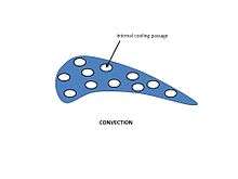
It works by passing cooling air through passages internal to the blade. Heat is transferred by conduction through the blade, and then by convection into the air flowing inside of the blade. A large internal surface area is desirable for this method, so the cooling paths tend to be serpentine and full of small fins. The internal passages in the blade may be circular or elliptical in shape. Cooling is achieved by passing the air through these passages from hub towards the blade tip. This cooling air comes from an air compressor. In case of gas turbine the fluid outside is relatively hot which passes through the cooling passage and mixes with the main stream at the blade tip.[25][26]
Impingement cooling
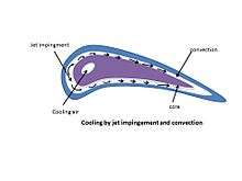
A variation of convection cooling, impingement cooling, works by hitting the inner surface of the blade with high velocity air. This allows more heat to be transferred by convection than regular convection cooling does. Impingement cooling is used in the regions of greatest heat loads. In case of turbine blades, the leading edge has maximum temperature and thus heat load. Impingement cooling is also used in mid chord of the vane. Blades are hollow with a core.[27] There are internal cooling passages. Cooling air enters from the leading edge region and turns towards the trailing edge.[26]
External cooling
Film cooling

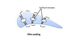
Film cooling (also called thin film cooling), a widely used type, allows for higher heat transfer rates than either convection and impingement cooling.[28] This technique consists of pumping the cooling air out of the blade through multiple small holes in the structure. A thin layer (the film) of cooling air is then created on the external surface of the blade, reducing the heat transfer from main flow, whose temperature (1300–1800 kelvins) can exceed the melting point of the blade material (1300–1400 kelvins).[29][30] The air holes can be in many different blade locations, but they are most often along the leading edge.[25] A United States Air Force program in the early 1970s funded the development of a turbine blade that was both film and convection cooled, and that method has become common in modern turbine blades.[8] Injecting the cooler bleed into the flow reduces turbine isentropic efficiency; the compression of the cooling air (which does not contribute power to the engine) incurs an energetic penalty; and the cooling circuit adds considerable complexity to the engine.[31] All of these factors have to be compensated by the increase in overall performance (power and efficiency) allowed by the increase in turbine temperature.[32]
Cooling effusion

The blade surface is made of porous material which means having a large number of small orifices on the surface. Cooling air is forced through these porous holes which forms a film or cooler boundary layer. Besides this uniform cooling is caused by effusion of the coolant over the entire blade surface.[24]
Pin fin cooling
In the narrow trailing edge film cooling is used to enhance heat transfer from the blade. There is an array of pin fins on the blade surface. Heat transfer takes place from this array and through the side walls. As the coolant flows across the fins with high velocity, the flow separates and wakes are formed. Many factors contribute towards heat transfer rate among which the type of pin fin and the spacing between fins are the most significant.[27]
Transpiration cooling
This is similar to film cooling in that it creates a thin film of cooling air on the blade, but it is different in that air is "leaked" through a porous shell rather than injected through holes. This type of cooling is effective at high temperatures as it uniformly covers the entire blade with cool air.[26][33] Transpiration-cooled blades generally consist of a rigid strut with a porous shell. Air flows through internal channels of the strut and then passes through the porous shell to cool the blade.[34] As with film cooling, increased cooling air decreases turbine efficiency, therefore that decrease has to be balanced with improved temperature performance.[32]
See also
Notes
- ↑ Creep is the tendency of a solid material to slowly move or deform permanently under the influence of stresses. It occurs as a result of long term exposure to high levels of stress that are below the yield strength of the material. Creep is more severe in materials that are subjected to heat for long periods, and near the melting point. Creep always increases with temperature. From Creep (deformation).
References
| Wikimedia Commons has media related to Turbine blades and vanes. |
- ↑ Boyce, p. 368.
- ↑ Bhagi LK, Rastogi V, Gupta P (2017). "Study of corrosive fatigue and life enhancement of low pressure steam turbine blade using friction dampers". Journal of Mechanical Science and Technology. 31: 17–27. doi:10.1007/s12206-016-1203-5.
- ↑ Flack, p. 406
- ↑ Flack, p. 407
- 1 2 Bhagi LK, Rastogi V, Gupta P (2013).Fractographic investigations of the failure of L-1 low pressure steam turbine blade. Case Studies in Engineering Failure Analysis, 1(2), pp.72-78
- 1 2 3 Flack, p. 429.
- ↑ Flack, p. 410
- 1 2 3 4 5 6 Koff, Bernard L. (2003). "Gas Turbine Technology Overview - A Designer's Perspective". AIAA/ICAS International Air and Space Symposium and Exposition: The Next 100 Years. 14–17 July 2003, Dayton, Ohio. AIAA 2003-2722.
- ↑ Dexclaux, Jacques and Serre, Jacque (2003). "M88-2 E4: Advanced New Generation Engine for Rafale Multirole Fighter". AIAA/ICAS International Air and Space Symposium and Exposition: The Next 100 Years. 14–17 July 2003, Dayton, Ohio. AIAA 2003-2610
- ↑ Magyar, Michael J. "Mineral Yearbook: Rhenium" (PDF). United States Geological Survey.
- ↑ Boyce, p. 449
- ↑ Flack, p. 430-3
- ↑ Takeshi, Takashi, Kuniyuki, Ken-ichi, Masato. "Development of CMC Turbine Parts for Aero Engines" (PDF).
- ↑ Halbig, Jaskowiak, Kiser, Zhu (June 2013). "Evaluation of Ceramic Matrix Composite Technology for Aircraft Turbine Engine Applications" (PDF). 51st AIAA Aerospace Sciences Meeting including the New Horizons Forum and Aerospace Exposition. doi:10.2514/6.2013-539.
- ↑ "Ceramic Matrix Composites Allow GE Jet Engines to Fly Longer - GE Reports". GE Reports. Retrieved 2015-11-02.
- ↑ "GE Successfully Tests World's First Rotating Ceramic Matrix Composite Material for Next-Gen Combat Engine | Press Release | GE Aviation". www.geaviation.com. Retrieved 2015-11-02.
- ↑ Boyce, p. 440-2
- 1 2 3 4 5 Schilke, P. W. (2004). Advanced Gas Turbine Materials and Coatings. GE Energy. August 2004. Retrieved: 25 May 2011.
- 1 2 3 4 MacKay, Rebecca A., et al. (2007). Low-Density, Creep-Resistant Superalloys Developed for Turbine Blades. NASA Glenn's Research & Technology. Updated: 7 November 2007. Retrieved: 16 June 2010.
- ↑ P. Caron, Y. Ohta, Y.G. Nakagawa, T. Khan (1988): Superalloys 1988 (edited by S. Reichmann et al.), p. 215. The Metallurgical Society of AIME, Warrendale, PA.
- ↑ S. Walston, A. Cetel, R. MacKay, K. O’Hara, D. Duhl, and R. Dreshfield (2004). Joint Development of a Fourth Generation Single Crystal Superalloy Archived 15 October 2006 at the Wayback Machine.. NASA TM—2004-213062. December 2004. Retrieved: 16 June 2010.
- ↑ "Metal Tidbits: Nimonic." steelforge.com. Retrieved: 5 March 2011.
- ↑ "Products." Archived 8 December 2012 at Archive.is Special Metals. Retrieved: 5 March 2011.
- 1 2 3 4 Yahya, S M (2011). Turbines Compressors and Fans. New delhi: Tata McGraw-Hill Education, 2010. pp. 430–433. ISBN 9780070707023.
- 1 2 3 Flack, p.428.
- 1 2 3 Boyce, p. 370.
- 1 2 Lesley M. Wright, Je-Chin Han. "Enhanced Internal Coolingof Turbine Blades and Vanes". 4.2.2.2 Enhanced Internal Coolingof Turbine Blades and Vanes. Retrieved 27 May 2013.
- ↑ Volume 1. Performance Flight Testing Phase. Chapter 7. Aero Propulsion page 7.122. Edwards Air Force Base, Air Force Test Center, February 1991. Size: 8MB. mirror of ADA320315.pdf
- ↑ What is Film Cooling?
- ↑ Martinez, Isidoro. "Aircraft propulsion. Thermal and mechanical limitations in jet engines" page 19. Technical University of Madrid, School of Aeronautical Engineering, 2015. Retrieved: April 2015.
- ↑ Rolls-Royce plc (2005). The Jet Engine (6 ed.). Rolls-Royce plc. ISBN 0902121235.
- 1 2 Boyce, p. 379-80
- ↑ Flack, p. 428-9
- ↑ Boyce, p. 375
- Bibliography
- YAHYA, SM (2011). "Chapter 10: High temperature(cooled) turbine stages". turbines, compressor and fans (4th ed.). New delhi: Tata McGraw Hill Education private limited. ISBN 978-0-07-070702-3.
- Flack, Ronald D. (2005). "Chapter 8: Axial Flow Turbines". Fundamentals of Jet Propulsion with Applications. Cambridge Aerospace Series. New York, NY: Cambridge University Press. ISBN 978-0-521-81983-1.
- Boyce, Meherwan P. (2006). "Chapter 9: Axial Flow Turbines and Chapter 11: Materials". Gas Turbine Engineering Handbook (3rd ed.). Oxford: Elsevier. ISBN 978-0-7506-7846-9.