NAND logic
Because the NAND function has functional completeness all logic systems can be converted into NAND gates – the mathematical proof for this was published by Henry M. Sheffer in 1913 in the Transactions of the American Mathematical Society (Sheffer 1913). This is also true for NOR gates. In principle, any combinatorial logic function can be realized with enough NAND gates.
NAND
A NAND gate is an inverted AND gate. It has the following truth table:
 | |||||||||||||||||||||
|
Q = A NAND B
| |||||||||||||||||||||
Making other gates by using NAND gates
A NAND gate is a universal gate, meaning that any other gate can be represented as a combination of NAND gates.
NOT
A NOT gate is made by joining the inputs of a NAND gate together. Since a NAND gate is equivalent to an AND gate followed by a NOT gate, joining the inputs of a NAND gate leaves only the NOT gate.
| Desired NOT Gate | NAND Construction | |||||||||
|---|---|---|---|---|---|---|---|---|---|---|
 |  | |||||||||
| Q = NOT( A ) | = A NAND A | |||||||||
| ||||||||||
AND
An AND gate is made by inverting the output of a NAND gate as shown below.
| Desired AND Gate | NAND Construction | ||||||||||||||||||||
|---|---|---|---|---|---|---|---|---|---|---|---|---|---|---|---|---|---|---|---|---|---|
 | 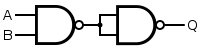 | ||||||||||||||||||||
| Q = A AND B | = ( A NAND B ) NAND ( A NAND B ) | ||||||||||||||||||||
| |||||||||||||||||||||
OR
If the truth table for a NAND gate is examined or by applying De Morgan's Laws, it can be seen that if any of the inputs are 0, then the output will be 1. To be an OR gate, however, the output must be 1 if any input is 1. Therefore, if the inputs are inverted, any high input will trigger a high output.
| Desired OR Gate | NAND Construction | ||||||||||||||||||||
|---|---|---|---|---|---|---|---|---|---|---|---|---|---|---|---|---|---|---|---|---|---|
 | 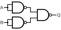 | ||||||||||||||||||||
| Q = A OR B | = ( A NAND A ) NAND ( B NAND B ) | ||||||||||||||||||||
| |||||||||||||||||||||
NOR
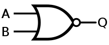
A NOR gate is an OR gate with an inverted output. Output is high when neither input A nor input B is high.
| Desired NOR Gate | NAND Construction | ||||||||||||||||||||
|---|---|---|---|---|---|---|---|---|---|---|---|---|---|---|---|---|---|---|---|---|---|
 |  | ||||||||||||||||||||
| Q = A NOR B | = [ ( A NAND A ) NAND ( B NAND B ) ] NAND [ ( A NAND A ) NAND ( B NAND B ) ] | ||||||||||||||||||||
| |||||||||||||||||||||
XOR
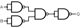
An XOR gate is made by connecting four NAND gates as shown below. This construction entails a propagation delay three times that of a single NAND gate.
| Desired XOR Gate | NAND Construction | ||||||||||||||||||||
|---|---|---|---|---|---|---|---|---|---|---|---|---|---|---|---|---|---|---|---|---|---|
 | 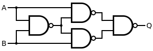 | ||||||||||||||||||||
| Q = A XOR B | = [ A NAND ( A NAND B ) ] NAND [ B NAND ( A NAND B ) ] | ||||||||||||||||||||
| |||||||||||||||||||||
Alternatively, the B-input of the XNOR gate with the 3-gate propagation delay can be inverted. This construction uses five gates instead of four.
| Desired Gate | NAND Construction |
|---|---|
|  |
| Q = A XOR B | = [ B NAND ( A NAND A ) ] NAND [ A NAND ( B NAND B ) ] |
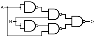
XNOR
An XNOR gate is made by connecting the output of 3 NAND gates (connected as an OR gate) and the output of a NAND gate to the respective inputs of a NAND gate. This construction entails a propagation delay three times that of a single NAND gate and uses five gates.
| Desired XNOR Gate | NAND Construction | ||||||||||||||||||||
|---|---|---|---|---|---|---|---|---|---|---|---|---|---|---|---|---|---|---|---|---|---|
 |  | ||||||||||||||||||||
| Q = A XNOR B | = [ ( A NAND A ) NAND ( B NAND B ) ] NAND ( A NAND B ) | ||||||||||||||||||||
| |||||||||||||||||||||
Alternatively, the 4-gate version of the XOR gate can be used with an inverter. This construction has a propagation delay four times (instead of three times) that of a single NAND gate.
| Desired Gate | NAND Construction |
|---|---|
| 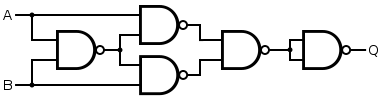 |
| Q = A XNOR B | = { [ A NAND ( A NAND B ) ] NAND [ B NAND ( A NAND B ) ] } NAND { [ A NAND ( A NAND B ) ] NAND [ B NAND ( A NAND B ) ] } |
MUX
A multiplexer or a MUX gate is a three-input gate that uses one of the inputs, called the selector bit, to select one of the other two inputs, called data bits, and outputs only the selected data bit.[1]
| Desired MUX Gate | NAND Construction | |||||||||||||||||||||||||||||||||||||||||||||
|---|---|---|---|---|---|---|---|---|---|---|---|---|---|---|---|---|---|---|---|---|---|---|---|---|---|---|---|---|---|---|---|---|---|---|---|---|---|---|---|---|---|---|---|---|---|---|
| Q = [ A AND NOT( S ) ] OR ( B AND S ) | = [ A NAND ( S NAND S ) ] NAND ( B NAND S ) | |||||||||||||||||||||||||||||||||||||||||||||
| ||||||||||||||||||||||||||||||||||||||||||||||
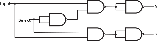
DEMUX
A demultiplexer performs the opposite function of a multiplexer: It takes a single input and channels it to one of two possible outputs according to a selector bit that specifies which output to choose.[1]
| Desired DEMUX Gate | NAND Construction | |||||||||||||||||||||||||
|---|---|---|---|---|---|---|---|---|---|---|---|---|---|---|---|---|---|---|---|---|---|---|---|---|---|---|
|
| ||||||||||||||||||||||||||
| ||||||||||||||||||||||||||
See also
- NOR logic. Like NAND gates, NOR gates are also universal gates.
- Functional Completeness
External links
- TTL NAND and AND gates - All About Circuits
- Steps to Derive XOR from NAND gate.
- NAND Gate, Demonstrate an interactive simulation of the NAND Gate circuit created with Teahlab's simulator.
References
- 1 2 Nisan, N. & Schocken, S., 2005. In: From NAND to Tetris: Building a Modern Computer from First Principles. s.l.:The MIT Press, p. 20. Available at: http://www.nand2tetris.org/chapters/chapter%2001.pdf
- Lancaster, Don (1974). TTL Cookbook (1st ed.). Indianapolis, IN: Howard W Sams. pp. 126–135. ISBN 0-672-21035-5.
- Sheffer, H. M. (1913), "A set of five independent postulates for Boolean algebras, with application to logical constants", Transactions of the American Mathematical Society, 14: 481–488, doi:10.2307/1988701, JSTOR 1988701