USB (Physical)
This article provides information about the physical aspects of Universal Serial Bus, USB: connectors, cabling, and power. The initial versions of the USB standard specified connectors that were easy to use and that would have acceptable life spans; revisions of the standard added smaller connectors useful for compact portable devices. Higher-speed development of the USB standard gave rise to another family of connectors to permit additional data paths. All versions of USB specify cable properties; version 3.X cables include additional data paths. The USB standard included power supply to peripheral devices; modern versions of the standard extend the power delivery limits for battery charging and devices requiring up to 100 watts. USB has been selected as the standard charging format for many mobile phones, reducing the proliferation of proprietary chargers.
Connectors
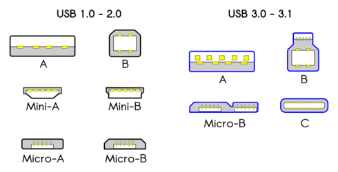
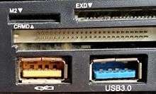
The three sizes of USB connectors are the default or standard format intended for desktop or portable equipment, the mini intended for mobile equipment , and the thinner micro size, for low-profile mobile equipment such as mobile phones and tablets. There are five speeds for USB data transfer: Low Speed, Full Speed, High Speed (from version 2.0 of the specification), SuperSpeed (from version 3.0), and SuperSpeed+ (from version 3.1). The modes have differing hardware and cabling requirements. USB devices have some choice of implemented modes, and USB version is not a reliable statement of implemented modes. Modes are identified by their names and icons, and the specifications suggests that plugs and receptacles be colour-coded (SuperSpeed is identified by blue).
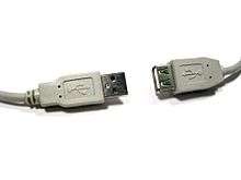
Unlike other data buses (such as Ethernet), USB connections are directed; a host device has "downstream" facing ports that connect to the "upstream" ports of devices. Only downstream facing ports provide power; this topology was chosen to easily prevent electrical overloads and damaged equipment. Thus, USB cables have different ends: A and B, with different physical connectors for each. Each format has a plug and receptacle defined for each of the A and B ends. USB cables have plugs, and the corresponding receptacles are on the computers or electronic devices. In common practice, the A end is usually the standard format, and the B side varies over standard, mini, and micro. The mini and micro formats also provide for USB On-The-Go with a hermaphroditic AB receptacle, which accepts either an A or a B plug. On-The-Go allows USB between peers without discarding the directed topology by choosing the host at connection time; it also allows one receptacle to perform double duty in space-constrained applications.
Connector properties
The connectors the USB committee specifies support a number of USB's underlying goals, and reflect lessons learned from the many connectors the computer industry has used. The female connector mounted on the host or device is called the receptacle, and the male connector attached to the cable is called the plug.[1] The official USB specification documents also periodically define the term male to represent the plug, and female to represent the receptacle.[2]
By design, it is difficult to insert a USB plug into its receptacle incorrectly. The USB specification requires that the cable plug and receptacle be marked so the user can recognize the proper orientation. [1] The type-C plug is reversible. USB cables and small USB devices are held in place by the gripping force from the receptacle, with no screws, clips, or thumb-turns as other connectors use.
The different A and B plugs prevent accidentally connecting two power sources. However, some of this directed topology is lost with the advent of multi-purpose USB connections (such as USB On-The-Go in smartphones, and USB-powered Wi-Fi routers), which require A-to-A, B-to-B, and sometimes Y/splitter cables. See the USB On-The-Go connectors section below for a more detailed summary description.
There are cables with A plugs on both ends, which may be valid if the cable includes, for example, a USB host-to-host transfer device with 2 ports.[3]
Durability
The standard connectors were designed to be more robust than many past connectors. This is because USB is hot-pluggable, and the connectors would be used more frequently, and perhaps with less care, than previous connectors.
Standard USB has a minimum rated lifetime of 1,500 cycles of insertion and removal,[4] the mini-USB receptacle increases this to 5,000 cycles,[4] and the newer Micro-USB[4] and USB-C receptacles are both designed for a minimum rated lifetime of 10,000 cycles of insertion and removal.[5] To accomplish this, a locking device was added and the leaf-spring was moved from the jack to the plug, so that the most-stressed part is on the cable side of the connection. This change was made so that the connector on the less expensive cable would bear the most wear.[6][4]
In standard USB, the electrical contacts in a USB connector are protected by an adjacent plastic tongue, and the entire connecting assembly is usually protected by an enclosing metal shell.[4]
The shell on the plug makes contact with the receptacle before any of the internal pins. The shell is typically grounded, to dissipate static electricity and to shield the wires within the connector.
Compatibility
The USB standard specifies tolerances for compliant USB connectors to minimize physical incompatibilities in connectors from different vendors. The USB specification also defines limits to the size of a connecting device in the area around its plug, so that adjacent ports are not blocked. Compliant devices must either fit within the size restrictions or support a compliant extension cable that does.
Pinouts
USB 2.0 uses two wires for power (VBUS and GND), and two for differential serial data signals. Mini and micro connectors have their GND connections moved from pin #4 to pin #5, while their pin #4 serves as an ID pin for the On-The-Go host/client identification.[7]
USB 3.0 provides two additional differential pairs (four wires, SSTx+, SSTx−, SSRx+ and SSRx−), providing full-duplex data transfers at SuperSpeed, which makes it similar to Serial ATA or single-lane PCI Express.
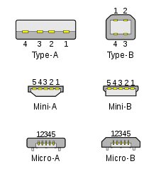
- Power (VBUS, 5 V)
- Data− (D−)
- Data+ (D+)
- ID (On-The-Go)
- GND
- SuperSpeed transmit− (SSTx−)
- SuperSpeed transmit+ (SSTx+)
- GND
- SuperSpeed receive− (SSRx−)
- SuperSpeed receive+ (SSRx+)
| Pin | Name | Wire color[lower-alpha 1] | Description | |
|---|---|---|---|---|
| 1 | VBUS | Red or | Orange | +5 V |
| 2 | D− | White or | Gold | Data− |
| 3 | D+ | Green | Data+ | |
| 4 | GND | Black or | Blue | Ground |
| Pin | Name | Wire color[lower-alpha 1] | Description |
|---|---|---|---|
| 1 | VBUS | Red | +5 V |
| 2 | D− | White | Data− |
| 3 | D+ | Green | Data+ |
| 4 | ID | No wire | On-The-Go ID distinguishes cable ends:
|
| 5 | GND | Black | Signal ground |
Colors
| Color | Location | Description | ||||||
|---|---|---|---|---|---|---|---|---|
| Black or white | Ports & plugs | Type-A or type-B | ||||||
| Blue (Pantone 300C) | Ports & plugs | Type-A or type-B, SuperSpeed | ||||||
| Teal blue | Ports & plugs | Type-A or type-B, SuperSpeed+ | ||||||
| Green | Ports & plugs | Type-A or type-B, Qualcomm Quick Charge[9] | ||||||
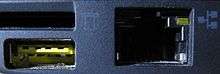
| Yellow, orange or red | Ports only | High-current or sleep-and-charge | ||||||
USB ports and connectors are often color-coded to distinguish their different functions and USB versions. These colors are not part of the USB specification and can vary between manufacturers; for example, USB 3.0 specification mandates appropriate color-coding while it only recommends blue inserts for standard-A USB 3.0 connectors and plugs.[10]
Connector types
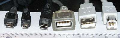
- Micro-B plug
- UC-E6[lower-alpha 1]
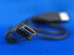
- Mini-B plug
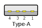
- type-A receptacle[lower-alpha 2]
- type-A plug
- type-B plug
USB connector types multiplied as the specification progressed. The original USB specification detailed standard-A and standard-B plugs and receptacles.The connectors were different so that users could not connect one computer receptacle to another. The data pins in the standard plugs are recessed compared to the power pins,so that the device can power up before establishing a data connection. Some devices operate in different modes depending on whether the data connection is made. Charging docks supply power and do not include a host device or data pins, allowing any capable USB device to charge or operate from a standard USB cable. Charging cables provide power connections, but not data. In a charge-only cable, the data wires are shorted at the device end, otherwise the device may reject the charger as unsuitable.
Standard connectors

The type-A plug has an elongated rectangular cross-section, inserts into a type-A receptacle on a downstream port on a USB host or hub, and carries both power and data. Captive cables on USB devices, such as keyboards or mice, terminate with a type-A plug.
The type-B plug has a near square cross-section with the top exterior corners beveled. As part of a removable cable, it inserts into an upstream port on a device, such as a printer. On some devices, the type-B receptacle has no data connections, being used solely for accepting power from the upstream device. This two-connector-type scheme (A/B) prevents a user from accidentally creating a loop.[11][12]
The maximum allowed cross-section of the overmold boot (which is part of the connector used for its handling) is 16 by 8 mm (0.63 by 0.31 in) for the standard-A plug type, while for the type-B it is 11.5 by 10.5 mm (0.45 by 0.41 in).[2]
Mini connectors
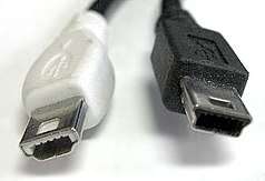
Mini-USB connectors were introduced together with USB 2.0 in April 2000, for use with smaller devices such as digital cameras, smartphones, and tablet computers. The Mini-A connector and the Mini-AB receptacle connector have been deprecated since May 2007.[13] Mini-B connectors are still supported, but are not On-The-Go-compliant;[14] the Mini-B USB connector was standard for transferring data to and from the early smartphones and PDAs. Both Mini-A and Mini-B plugs are approximately 3 by 7 mm (0.12 by 0.28 in).
Micro connectors
Micro-USB connectors, which were announced by the USB-IF on 4 January 2007,[15][16] have a similar width to Mini-USB, but approximately half the thickness, enabling their integration into thinner portable devices. The Micro-A connector is 6.85 by 1.8 mm (0.270 by 0.071 in) with a maximum overmold boot size of 11.7 by 8.5 mm (0.46 by 0.33 in), while the Micro-B connector is 6.85 by 1.8 mm (0.270 by 0.071 in) with a maximum overmold size of 10.6 by 8.5 mm (0.42 by 0.33 in).[8]
The thinner Micro-USB connectors were introduced to replace the Mini connectors in devices manufactured since May 2007, including smartphones, personal digital assistants, and cameras.[17]
The Micro plug design is rated for at least 10,000 connect-disconnect cycles, which is more than the Mini plug design.[15][18] The Micro connector is also designed to reduce the mechanical wear on the device; instead the easier-to-replace cable is designed to bear the mechanical wear of connection and disconnection. The Universal Serial Bus Micro-USB Cables and Connectors Specification details the mechanical characteristics of Micro-A plugs, Micro-AB receptacles (which accept both Micro-A and Micro-B plugs), Double-Sided Micro USB, and Micro-B plugs and receptacles,[18] along with a standard-A receptacle to Micro-A plug adapter.
OMTP standard
Micro-USB was endorsed as the standard connector for data and power on mobile devices by the cellular phone carrier group Open Mobile Terminal Platform (OMTP) in 2007.[19]
Micro-USB was embraced as the "Universal Charging Solution" by the International Telecommunication Union (ITU) in October 2009.[20]
In Europe, micro-USB became the defined common external power supply (EPS) for use with smartphones sold in the EU,[21] 14 of the world's largest mobile phone manufacturers signed the EU's common EPS Memorandum of Understanding (MoU).[22][23] Apple, one of the original MoU signers, makes Micro-USB adapters available – as permitted in the Common EPS MoU – for its iPhones equipped with Apple's proprietary 30-pin dock connector or (later) Lightning connector.[24][25] according to the CEN, CENELEC, and ETSI.
USB 3.x connectors and backward compatibility
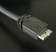
USB 3.0 introduced Type-A SuperSpeed plugs and receptacles as well as micro-sized Type-B SuperSpeed plugs and receptacles. The 3.0 receptacles are backward-compatible with the corresponding pre-3.0 plugs.
USB 3.x and USB 1.x Type-A plugs and receptacles are designed to interoperate. To achieve USB 3.0's SuperSpeed (and SuperSpeed+ for USB 3.1 Gen 2), 5 extra pins are added to the unused area of the original 4 pin USB 1.0 design, making USB 3.0 Type-A plugs and receptacles backward compatible to those of USB 1.0.
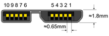
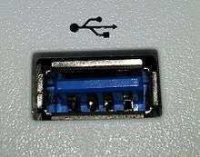
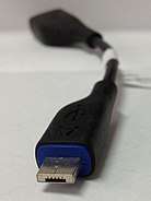
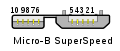
On the device side, a modified Micro-B plug (Micro-B SuperSpeed) is used to cater for the five additional pins required to achieve the USB 3.0 features (USB Type-C plug can also be used). The USB 3.0 Micro-B plug effectively consists of a standard USB 2.0 Micro-B cable plug, with an additional 5 pins plug "stacked" to the side of it. In this way, cables with smaller 5 pin USB 2.0 Micro-B plugs can be plugged into devices with 10 contact USB 3.0 Micro-B receptacles and achieve backward compatibility.
USB cables exist with various combinations of plugs on each end of the cable, as displayed below in the USB cables matrix.
.jpg)
USB On-The-Go connectors
USB On-The-Go (OTG) introduces the concept of a device performing both master and slave roles. All current OTG devices are required to have one, and only one, USB connector: a Micro-AB receptacle. (In the past, before the development of Micro-USB, On-The-Go devices used Mini-AB receptacles).
The Micro-AB receptacle is capable of accepting both Micro-A and Micro-B plugs, attached to any of the legal cables and adapters as defined in revision 1.01 of the Micro-USB specification.
To enable Type-AB receptacles to distinguish which end of a cable is plugged in, plugs have an "ID" pin in addition to the four contacts in standard-size USB connectors. This ID pin is connected to GND in Type-A plugs, and left unconnected in Type-B plugs. Typically, a pull-up resistor in the device is used to detect the presence or absence of an ID connection.
The OTG device with the A-plug inserted is called the A-device and is responsible for powering the USB interface when required, and by default assumes the role of host. The OTG device with the B-plug inserted is called the B-device and by default assumes the role of peripheral. An OTG device with no plug inserted defaults to acting as a B-device. If an application on the B-device requires the role of host, then the Host Negotiation Protocol (HNP) is used to temporarily transfer the host role to the B-device.
OTG devices attached either to a peripheral-only B-device or a standard/embedded host have their role fixed by the cable, since in these scenarios it is only possible to attach the cable one way.
USB-C

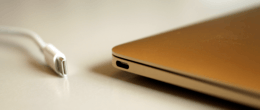
Developed at roughly the same time as the USB 3.1 specification, but distinct from it, the USB Type-C Specification 1.0 was finalized in August 2014[26] and defines a new small reversible-plug connector for USB devices.[27] The Type-C plug connects to both hosts and devices, replacing various Type-A and Type-B connectors and cables with a standard meant to be future-proof.[26][28]
The 24-pin double-sided connector provides four power-ground pairs, two differential pairs for USB 2.0 data bus (though only one pair is implemented in a Type-C cable), four pairs for SuperSpeed data bus (only two pairs are used in USB 3.1 mode), two "sideband use" pins, VCONN +5 V power for active cables, and a configuration pin for cable orientation detection and dedicated biphase mark code (BMC) configuration data channel.[29][30] Type-A and Type-B adaptors and cables are required for older devices to plug into Type-C hosts. Adapters and cables with a Type-C receptacle are not allowed.[31]
Full-featured USB 3.1 Type-C cables are electronically marked cables that contain a full set of wires and a chip with an ID function based on the configuration data channel and vendor-defined messages (VDMs) from the USB Power Delivery 2.0 specification. USB Type-C devices also support power currents of 1.5 A and 3.0 A over the 5 V power bus in addition to baseline 900 mA; devices can either negotiate increased USB current through the configuration line or they can support the full Power Delivery specification using both BMC-coded configuration line and legacy BFSK-coded VBUS line.
Alternate Mode dedicates some of the physical wires in the USB-C cable for direct device-to-host transmission of alternate data protocols. The four high-speed lanes, two sideband pins, and—for dock, detachable device and permanent cable applications only—two USB 2.0 pins and one configuration pin can be used for Alternate Mode transmission. The modes are configured using VDMs through the configuration channel.
Host and device interface receptacles
USB plugs fit one receptacle with notable exceptions for USB On-The-Go "AB" support and the general backward compatibility of USB 3.0 as shown.
| Plug | ||||||||||
|---|---|---|---|---|---|---|---|---|---|---|
 |
 |
 |
 |
 |
 |
 |
 |
| ||
 |
Yes | Only non- SuperSpeed |
No | No | No | No | No | No | No | No |
 |
Only non- SuperSpeed |
Yes | No | No | No | No | No | No | No | No |
 |
No | No | Yes | No | No | No | No | No | No | No |
 |
No | No | Only non- SuperSpeed |
Yes | No | No | No | No | No | No |
| No | No | No | No | Deprecated | No | No | No | No | No | |
| No | No | No | No | Deprecated | Deprecated | No | No | No | No | |
| No | No | No | No | No | Yes | No | No | No | No | |
| No | No | No | No | No | No | Yes | Yes | No | No | |
| No | No | No | No | No | No | No | Yes | No | No | |
| No | No | No | No | No | No | No | Only non- SuperSpeed |
Yes | No | |
|
No | No | No | No | No | No | No | No | No | Yes |
| Plugs, each end | |
|
|
|
|
|
|
|
|---|---|---|---|---|---|---|---|---|
|
Non- standard |
Non- standard |
Non- standard |
Yes | Yes | Yes | Yes | Yes |
|
Non- standard |
No | No | Deprecated | Deprecated | Non- standard |
No | No |
|
Non- standard |
No | No | Non- standard |
Non- standard |
Yes | No | No |
|
Yes | Deprecated | Non- standard |
No | No | No | No | Yes |
|
Yes | Deprecated | Non- standard |
No | Non- standard |
No | No | Yes |
|
Yes | Non- standard |
Yes | No | No | No | No | Yes |
|
Yes | No | No | No | No | No | No | Yes |
|
Yes | No | No | Yes | Yes | Yes | Yes | Yes |
- Non-standard
- Existing for specific proprietary purposes, and in most cases not inter-operable with USB-IF compliant equipment. In addition to the above cable assemblies comprising two plugs, an "adapter" cable with a Micro-A plug and a standard-A receptacle is compliant with USB specifications.[8] Other combinations of connectors are not compliant.There do exist A-to-A assemblies, referred to as cables (such as the Easy Transfer Cable); however, these have a pair of USB devices in the middle, making them more than just cables.
- Deprecated
- Some older devices and cables with Mini-A connectors have been certified by USB-IF. The Mini-A connector is obsolete: no new Mini-A connectors and neither Mini-A nor Mini-AB receptacles will be certified.[13]Note: Mini-B is not deprecated, although it is less and less used since the arrival of Micro-B.
Proprietary connectors and formats
Manufacturers of personal electronic devices might not include a USB standard connector on their product for technical or marketing reasons.[32] Some manufacturers provide proprietary cables that permit their devices to physically connect to a USB standard port. Full functionality of proprietary ports and cables with USB standard ports is not assured; for example, some devices only use the USB connection for battery charging and do not implement any data transfer functions.[33]
Some manufacturers now offer USB magnetic port adapters; as of 2018 all product are proprietary incompatible designs. Magnetic connectors were developed mainly for mobile phones devices having Micro B, type-C or Apple's Lightning ports. They offer ease of operation and are also intended to protect the mobile device's connector from deteriorating under the mechanical action of connecting and disconnecting.
Cabling
The D± signals used by low, full, and high speed are carried over a twisted pair (typically, unshielded) to reduce noise and crosstalk. SuperSpeed uses separate transmit and receive differential pairs, which additionally require shielding (typically, shielded twisted pair but twinax is also mentioned by the specification). Thus, to support SuperSpeed data transmission, cables contain twice as many wires and are thus larger in diameter.[34]
The USB 1.1 standard specifies that a standard cable can have a maximum length of 5 meters (16 ft 5 in) with devices operating at full speed (12 Mbit/s), and a maximum length of 3 meters (9 ft 10 in) with devices operating at low speed (1.5 Mbit/s).[35][36][37]
USB 2.0 provides for a maximum cable length of 5 meters (16 ft 5 in) for devices running at high speed (480 Mbit/s). The primary reason for this limit is the maximum allowed round-trip delay of about 1.5 μs. If USB host commands are unanswered by the USB device within the allowed time, the host considers the command lost. When adding USB device response time, delays from the maximum number of hubs added to the delays from connecting cables, the maximum acceptable delay per cable amounts to 26 ns.[38] The USB 2.0 specification requires that cable delay be less than 5.2 ns/m (1.6 ns/ft), (192000 km/s) - which is close to the maximum achievable transmission speed for standard copper wire).
The USB 3.0 standard does not directly specify a maximum cable length, requiring only that all cables meet an electrical specification: for copper cabling with AWG 26 wires the maximum practical length is 3 meters (9 ft 10 in).[39]
Power
| Specification | Current | Voltage | Power (max) |
|---|---|---|---|
| Low-power device | 100 mA | 5 V | 0.50 W |
| Low-power SuperSpeed (USB 3.0) device | 150 mA | 5 V | 0.75 W |
| High-power device | 500 mA[lower-alpha 1] | 5 V | 2.5 W |
| High-power SuperSpeed (USB 3.0) device | 900 mA[lower-alpha 2] | 5 V | 4.5 W |
| Multi-lane SuperSpeed (USB 3.2 Gen x2) device | 1.5 A[lower-alpha 3] | 5 V | 7.5 W |
| Battery Charging (BC) 1.2 | 1.5 A | 5 V | 7.5 W |
| Type-C | 1.5 A | 5 V | 7.5 W |
| 3 A | 5 V | 15 W | |
| Power Delivery 2.0 Micro-USB | 3 A | 20 V | 60 W |
| Power Delivery 2.0 Type-A/B/C[lower-alpha 4] | 5 A | 20 V | 100 W |
USB supplies power at 5 V ± 5% to power USB downstream devices. To allows for voltage drops, the voltage at the hub port is specified in the range 5.00+0.25
−0.60 V by USB 2.0, and 5.00+0.25
−0.55 V[40] by USB 3.0. Devices' configuration and low-power functions must operate down to 4.40 V at the hub port by USB 2.0 and that devices' configuration, low-power, and high-power functions must operate down to 4.00 V at the device port by USB 3.0.
The limit to device power draw is stated in terms of a unit load, which is 100 mA or 150 mA for SuperSpeed devices. Low-power devices may draw at most 1 unit load, and all devices must act as low-power devices before they are configured. High-power devices draw at most 5 unit loads (500 mA) or 6 unit loads (900 mA) for SuperSpeed devices. A high-powered device must be configured, and may only draw as much power as specified in its configuration.[41][42][43][44] I.e., the maximum power may not be available.
A bus-powered hub is a high-power device providing low-power ports. It draws 1 unit load for the hub controller and 1 unit load for each of at most 4 ports. The hub may also have some non-removable functions in place of ports. A self-powered hub is a device that provides high-power ports. Optionally, the hub controller may draw power for its operation as a low-power device, but all high-power ports draw from the hub's self-power.
Where devices (for example, high-speed disk drives) require more power than a high-power device can draw,[45] they function erratically, if at all, from bus power of a single port. USB provides for these devices as being self-powered. However, such devices may come with a Y-shaped cable that has two USB plugs (one for power and data, the other for only power), so as to draw power as two devices.[46] Such a cable is non-standard, with the USB compliance specification stating that "use of a 'Y' cable (a cable with two A-plugs) is prohibited on any USB peripheral", meaning that "if a USB peripheral requires more power than allowed by the USB specification to which it is designed, then it must be self-powered."[47]
USB Battery Charging
USB Battery Charging defines a charging port, which may be a charging downstream port (CDP), with data, or a dedicated charging port (DCP) without data. Dedicated charging ports can be found on USB power adapters to run attached devices and battery packs. Charging ports on a host with both kinds will be labelled. [48]
The charging device identifies a charging port by non-data signaling on the D+ and D− terminals. A dedicated charging port places a resistance not exceeding 200 Ω across the D+ and D− terminals.[48][49]
Per the base specification, any device attached to a standard downstream port (SDP) must initially be a low-power device, with high-power mode contingent on later USB configuration by the host. Charging ports, however, can immediately supply between 0.5 and 1.5 A of current. The charging port must not apply current limiting below 0.5 A, and must not shut down below 1.5 A or before the voltage drops to 2 V.[48]
Since these currents are larger than in the original standard, the extra voltage drop in the cable reduces noise margins, causing problems with High Speed signaling. Battery Charging Specification 1.1 specifies that charging devices must dynamically limit bus power current draw during High Speed signaling;[50] 1.2 specifies that charging devices and ports must be designed to tolerate the higher ground voltage difference in High Speed signaling.
Revision 1.2 of the specification was released in 2010. Several changes are made and limits are increased including allowing 1.5 A on charging downstream ports for unconfigured devices, allowing High Speed communication while having a current up to 1.5 A, and allowing a maximum current of 5 A. Also, support is removed for charging port detection via resistive mechanisms.[51]
Before the Battery Charging Specification was defined, there was no standardized way for the portable device to inquire how much current was available. For example, Apple's iPod and iPhone chargers indicate the available current by voltages on the D− and D+ lines. When D+ = D− = 2.0 V, the device may pull up to 500 mA. When D+ = 2.0 V and D− = 2.8 V, the device may pull up to 1 A of current.[52] When D+ = 2.8 V and D− = 2.0 V, the device may pull up to 2 A of current.[53]
Accessory charging adaptors (ACA)
Portable devices having an USB On-The-Go port may want to charge and access USB peripheral at the same time, but having only a single port (both due to On-The-Go and space requirement) prevents this. Accessory charging adapters (ACA) are devices that provide portable charging power to an On-The-Go connection between host and peripheral.
ACAs have three ports: the OTG port for the portable device, which is required to have a Micro-A plug on a captive cable; the accessory port, which is required to have a Micro-AB or type-A receptacle; and the charging port, which is required to have a Micro-B receptacle, or type-A plug or charger on a captive cable. The ID pin of the OTG port is not connected within plug as usual, but to the ACA itself, where signals outside the OTG floating and ground states are used for ACA detection and state signaling. The charging port does not pass data, but does use the D± signals for charging port detection. The accessory port acts as any other port. When appropriately signaled by the ACA, the portable device can charge from the bus power as if there were a charging port present; any OTG signals over bus power are instead passed to the portable device via the ID signal. Bus power is also provided to the accessory port from the charging port transparently.[48]
Power Delivery (PD)
| Profile | +5 V | +12 V | +20 V |
|---|---|---|---|
| 0 | Reserved | ||
| 1 | 2.0 A, 10 W[lower-alpha 1] | N/A | N/A |
| 2 | 1.5 A, 18 W | ||
| 3 | 3.0 A, 36 W | ||
| 4 | 3.0 A, 60 W | ||
| 5 | 5.0 A, 60 W | 5.0 A, 100 W | |
| |||
| Source output power (W) |
Current, at: (A) | |||
|---|---|---|---|---|
| +5 V | +9 V | +15 V | +20 V | |
| 0.5–15 | 0.1–3.0 | N/A | N/A | N/A |
| 15–27 | 3.0 (15 W) |
1.67–3.0 | ||
| 27–45 | 3.0 (27 W) |
1.8–3.0 | ||
| 45–60 | 3.0 (45 W) |
2.25–3.0 | ||
| 60–100 | 3.0–5.0 | |||
In July 2012, the USB Promoters Group announced the finalization of the USB Power Delivery (PD) Specification (USB PD rev. 1), an extension that specifies using certified PD aware USB cables with standard USB Type-A and Type-B connectors to deliver increased power (more than 7.5 W) to devices with larger power demand. Devices can request higher currents and supply voltages from compliant hosts – up to 2 A at 5 V (for a power consumption of up to 10 W), and optionally up to 3 A or 5 A at either 12 V (36 W or 60 W) or 20 V (60 W or 100 W).[57] In all cases, both host-to-device and device-to-host configurations are supported.[58]
The intent is to permit uniformly charging laptops, tablets, USB-powered disks and similarly higher-power consumer electronics, as a natural extension of existing European and Chinese mobile telephone charging standards. This may also affect the way electric power used for small devices is transmitted and used in both residential and public buildings.[59][60] The standard is designed to coexist with the previous USB Battery Charging specification.[61]
The first Power Delivery Specification defined six fixed power profiles for the power sources. PD-aware devices implement a flexible power management scheme by interfacing with the power source through a bidirectional data channel and requesting a certain level of electrical power, variable up to 5 A and 20 V depending on supported profile. The power configuration protocol uses a 24 MHz BFSK-coded transmission channel on the VBUS line.
The USB Power Delivery Specification revision 2.0 (USB PD rev. 2) has been released as part of the USB 3.1 suite.[55][62] It covers the Type-C cable and connector with four power/ground pairs and a separate configuration channel, which now hosts a DC coupled low-frequency BMC-coded data channel that reduces the possibilities for RF interference.[63] Power Delivery protocols have been updated to facilitate Type-C features such as cable ID function, Alternate Mode negotiation, increased VBUS currents, and VCONN-powered accessories.
As of USB Power Delivery Specification revision 2.0, version 1.2, the six fixed power profiles for power sources have been deprecated.[64] USB PD Power Rules replace power profiles, defining four normative voltage levels at 5 V, 9 V, 15 V, and 20 V. Instead of six fixed profiles, power supplies may support any maximum source output power from 0.5 W to 100 W.
The USB Power Delivery Specification revision 3.0 defines a programmable power supply protocol that allows granular control over VBUS power in 20 mV steps to facilitate constant current or constant voltage charging. Revision 3.0 also adds extended configuration messages, fast role swap, and deprecates the BFSK protocol.[56][65][66]
As of April 2016, there are silicon controllers available from several sources such as TI and Cypress.[67][68] Power supplies bundled with Type-C based laptops from Apple, Google, HP, Dell, and Razer support USB PD.[69] In addition, accessories from third party vendors including Anker,[70] Belkin,[71][72] iVoler,[73] and Innergie[74] support USB PD rev. 2 at multiple voltages. Asus make a PD compliant adapter card, the USB 3.1 UPD Panel.[75]
On 8 January 2018 USB-IF announced "Certified USB Fast Charger" which will certify chargers that use the feature "Programmable Power Supply" (PPS) of the USB Power Delivery 3.0 specification.[76]
Prior to Power Delivery, mobile phone vendors used custom protocols to exceed the 7.5 W cap on USB-BCS. For example, Qualcomm's Quick Charge 2.0 is able to deliver 18 W at a higher voltage, and VOOC delivers 20 W at the normal 5 V.[77] Some of these technologies, such as Quick Charge 4, eventually become compatible with USB-PD again.[78]
Sleep-and-charge ports
Sleep-and-charge USB ports can be used to charge electronic devices even when the computer is switched off. Normally, when a computer is powered off the USB ports are powered down, preventing phones and other devices from charging. Sleep-and-charge USB ports remain powered even when the computer is off. On laptops, charging devices from the USB port when it is not being powered from AC drains the laptop battery faster; most laptops have a facility to stop charging if their own battery charge level gets too low.[79] This feature has also been implemented on some laptop docking stations allowing device charging even when no laptop is present.[80]
Sleep-and-charge USB ports may be found colored differently than regular ports, mostly red or yellow, though that is not always the case.
On Dell and Toshiba laptops, the port is marked with the standard USB symbol with an added lightning bolt icon on the right side. Dell calls this feature PowerShare,[81] while Toshiba calls it USB Sleep-and-Charge.[82] On Acer Inc. and Packard Bell laptops, sleep-and-charge USB ports are marked with a non-standard symbol (the letters USB over a drawing of a battery); the feature is simply called Power-off USB.[83]
Mobile device charger standards
In China
As of 14 June 2007, all new mobile phones applying for a license in China are required to use a USB port as a power port for battery charging.[84][85] This was the first standard to use the convention of shorting D+ and D− in the charger.[86]
OMTP/GSMA Universal Charging Solution
In September 2007, the Open Mobile Terminal Platform group (a forum of mobile network operators and manufacturers such as Nokia, Samsung, Motorola, Sony Ericsson, and LG) announced that its members had agreed on Micro-USB as the future common connector for mobile devices.[87][88]
The GSM Association (GSMA) followed suit on 17 February 2009,[89][89][90][91][92] and on 22 April 2009, this was further endorsed by the CTIA – The Wireless Association,[93] with the International Telecommunication Union (ITU) announcing on 22 October 2009 that it had also embraced the Universal Charging Solution as its "energy-efficient one-charger-fits-all new mobile phone solution," and added: "Based on the Micro-USB interface, UCS chargers will also include a 4-star or higher efficiency rating—up to three times more energy-efficient than an unrated charger."[94]
EU smartphone power supply standard
In June 2009, many of the world's largest mobile phone manufacturers signed an EC-sponsored Memorandum of Understanding (MoU), agreeing to make most data-enabled mobile phones marketed in the European Union compatible with a common External Power Supply (common EPS). The EU's common EPS specification (EN 62684:2010) references the USB Battery Charging Specification and is similar to the GSMA/OMTP and Chinese charging solutions.[95][96] In January 2011, the International Electrotechnical Commission (IEC) released its version of the (EU's) common EPS standard as IEC 62684:2011.[97]
Non-standard devices
Some USB devices require more power than is permitted by the specifications for a single port. This is common for external hard and optical disc drives, and generally for devices with motors or lamps. Such devices can use an external power supply, which is allowed by the standard, or use a dual-input USB cable, one input of which is for power and data transfer, the other solely for power, which makes the device a non-standard USB device. Some USB ports and external hubs can, in practice, supply more power to USB devices than required by the specification but a standard-compliant device may not depend on this.
In addition to limiting the total average power used by the device, the USB specification limits the inrush current (i.e., the current used to charge decoupling and filter capacitors) when the device is first connected. Otherwise, connecting a device could cause problems with the host's internal power. USB devices are also required to automatically enter ultra low-power suspend mode when the USB host is suspended. Nevertheless, many USB host interfaces do not cut off the power supply to USB devices when they are suspended.[98]
Some non-standard USB devices use the 5 V power supply without participating in a proper USB network, which negotiates power draw with the host interface. These are usually called USB decorations. Examples include USB-powered keyboard lights, fans, mug coolers and heaters, battery chargers, miniature vacuum cleaners, and even miniature lava lamps. In most cases, these items contain no digital circuitry, and thus are not standard-compliant USB devices. This may cause problems with some computers, such as drawing too much current and damaging circuitry. Prior to the USB Battery Charging Specification, the USB specification required that devices connect in a low-power mode (100 mA maximum) and communicate their current requirements to the host, which then permits the device to switch into high-power mode.
Some devices, when plugged into charging ports, draw even more power (10 watts at 2.1 amperes) than the Battery Charging Specification allows — The iPad is one such device; [99] it negotiates the current pull with data pin voltages.[52] Barnes & Noble Nook Color devices also require a special charger that runs at 1.9 amperes.[100]
PoweredUSB
PoweredUSB is a proprietary extension that adds four additional pins supplying up to 6 A at 5 V, 12 V, or 24 V. It is commonly used in point of sale systems to power peripherals such as barcode readers, credit card terminals, and printers.
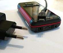 The Micro-USB interface is commonly found on chargers for mobile phones
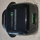 An AC adaptor with a green USB connector supporting Qualcomm Quick Charge 2.0
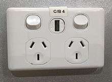 Australian and New Zealand power socket with USB charger socket
 Y-shaped USB 3.0 cable; with such a cable, a device can draw power from two USB ports simultaneously
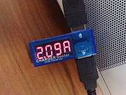 A small device that provides voltage and current readouts for devices charged over USB
_meter_2.jpg) This USB power meter additionally provides a charge readout (in mAh) and data logging
This USB power meter additionally provides a charge readout (in mAh) and data logging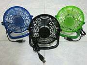 USB-powered mini fans
 USB-powered vacuum cleaner
References
- 1 2 Universal Serial Bus 3.0 Specification: Revision 1.0. Contributors: Hewlett-Packard, Intel, Microsoft, NEC, ST-Ericsson, Texas Instruments. 6 June 2011. p. 531. Archived from the original on 30 December 2013. Retrieved 26 July 2011.
- 1 2 "USB 2.0 Specification Engineering Change Notice (ECN) #1: Mini-B connector" (PDF). 20 October 2000. Archived (PDF) from the original on 12 April 2015. Retrieved 29 December 2014 – via www.usb.org.
- ↑ "USB connector guide". C2G. Archived from the original on 21 April 2014. Retrieved 2 December 2013.
- 1 2 3 4 5 "Universal Serial Bus Cables and Connectors Class Document Revision 2.0" (PDF). usb.org. August 2007. Archived from the original (PDF) on 11 June 2014. Retrieved 3 December 2013.
- ↑ Howse, Brett. "USB Type-C Connector Specifications Finalized". AnandTech. Anadtech. Archived from the original on 18 March 2017. Retrieved 24 April 2017.
- ↑ "Why was Mini-USB deprecated in favor of Micro-USB?". Stack exchange. 2011. Archived from the original on 7 December 2013. Retrieved 3 December 2013.
- ↑ "USB Pinout". usbpinout.net. Archived from the original on 17 June 2014. Retrieved 23 June 2014.
- 1 2 3 "Universal Serial Bus Micro-USB Cables and Connectors Specification" (PDF). USB Implementers Forum. 2007-04-04. Archived from the original (PDF) on 2015-01-31. Retrieved 2015-01-31.
- ↑ "Qualcomm Certified Nekteck Quick Charge 2.0 54W 4 Ports USB Rapid Turbo Car Charger". Retrieved 19 July 2017.
- ↑ "Universal Serial Bus Revision 3.0 Specification, Sections 3.1.1.1 and 5.3.1.3" (ZIP). usb.org. Archived from the original on 19 May 2014. Retrieved 19 May 2014.
- ↑ Quinnell, Richard A (24 October 1996). "USB: a neat package with a few loose ends". EDN Magazine. Reed. Archived from the original on 23 May 2013. Retrieved 18 February 2013.
- ↑ "What is the Difference between USB Type A and USB Type B Plug/Connector?". Archived from the original on 7 February 2017.
- 1 2 "Deprecation of the Mini-A and Mini-AB Connectors" (PDF) (Press release). USB Implementers Forum. 27 May 2007. Archived (PDF) from the original on 6 March 2009. Retrieved 13 January 2009.
- ↑ "ID Pin Resistance on Mini B-plugs and Micro B-plugs Increased to 1 Mohm". USB IF Compliance Updates. December 2009. Archived from the original on 20 July 2011. Retrieved 1 March 2010.
- 1 2 Universal Serial Bus Cables and Connectors Class Document (PDF), Revision 2.0, USB Implementers Forum, August 2007, p. 6, archived (PDF) from the original on 27 April 2015, retrieved 17 August 2014
- ↑ "Mobile phones to adopt new, smaller USB connector" (PDF) (Press release). USB Implementers Forum. 4 January 2007. Archived (PDF) from the original on 8 January 2007. Retrieved 8 January 2007.
- ↑ "Micro-USB pinout and list of compatible smartphones and other devices". pinoutsguide.com. Archived from the original on 10 October 2013.
- 1 2 "Universal Serial Bus Micro-USB Cables and Connectors Specification to the USB 2.0 Specification, Revision 1.01". USB Implementers Forum. 7 April 2007. Archived from the original (Zip) on 7 February 2012. Retrieved 18 November 2010.
Section 1.3: Additional requirements for a more rugged connector that is durable past 10,000 cycles and still meets the USB 2.0 specification for mechanical and electrical performance was also a consideration. The Mini-USB could not be modified and remain backward compatible to the existing connector as defined in the USB OTG specification.
- ↑ "OMTP Local Connectivity: Data Connectivity". Open Mobile Terminal Platform. 17 September 2007. Archived from the original on 15 October 2008. Retrieved 2009-02-11.
- ↑ "Universal phone charger standard approved—One-size-fits-all solution will dramatically cut waste and GHG emissions". ITU (press release). Pressinfo. 22 October 2009. Archived from the original on 5 November 2009. Retrieved 4 November 2009.
- ↑ "Commission welcomes new EU standards for common mobile phone charger". Press Releases. Europa. 29 December 2010. Archived from the original on 19 March 2011. Retrieved 22 May 2011.
- ↑ New EU standards for common mobile phone charger (press release), Europa, archived from the original on 3 January 2011
- ↑ The following 10 biggest mobile phone companies have signed the MoU: Apple, LG, Motorola, NEC, Nokia, Qualcomm, Research In Motion, Samsung, Sony Ericsson, Texas Instruments (press release), Europa, archived from the original on 2009-07-04
- ↑ "Nice Micro-USB adapter Apple, now sell it everywhere", Giga om, 5 October 2011, archived from the original on 26 August 2012
- ↑ "Apple's Lightning to Micro-USB adapter now available in US, not just Europe anymore", Engadget, 3 November 2012, archived from the original on 26 June 2017
- 1 2 Howse, Brett (12 August 2014). "USB Type-C Connector Specifications Finalized". Archived from the original on 28 December 2014. Retrieved 28 December 2014.
- ↑ Hruska, Joel (13 March 2015). "USB-C vs. USB 3.1: What's the difference?". ExtremeTech. Archived from the original on 11 April 2015. Retrieved 9 April 2015.
- ↑ Ngo, Dong (22 August 2014). "USB Type-C: One Cable to Connect Them All". c|net. Archived from the original on 2015-03-07. Retrieved 28 December 2014.
- ↑ "Technical Introduction of the New USB Type-C Connector". Archived from the original on 29 December 2014. Retrieved 29 December 2014.
- ↑ Smith, Ryan (22 September 2014). "DisplayPort Alternate Mode for USB Type-C Announced - Video, Power, & Data All Over Type-C". AnandTech. Archived from the original on 18 December 2014. Retrieved 28 December 2014.
- ↑ Universal Serial Bus Type-C Cable and Connector Specification Revision 1.1 (April 3, 2015), section 2.2, page 20
- ↑ "Proprietary Cables vs Standard USB". anythingbutipod.com. 30 April 2008. Archived from the original on 13 November 2013. Retrieved 29 October 2013.
- ↑ Lex Friedman (25 February 2013). "Review: Logitech's Ultrathin mini keyboard cover makes the wrong tradeoffs". macworld.com. Archived from the original on 3 November 2013. Retrieved 29 October 2013.
- ↑ "What is the USB 3.0 Cable Difference". Hantat. 18 May 2009. Archived from the original on 11 December 2011. Retrieved 12 December 2011.
- ↑ "USB Cable Length Limitations" (PDF). cablesplususa.com. 3 November 2010. Archived from the original (PDF) on 11 October 2014. Retrieved 2 February 2014.
- ↑ "What is the Maximum Length of a USB Cable?". Techwalla.com. Archived from the original on 1 December 2017. Retrieved 18 November 2017.
- ↑ "Cables and Long-Haul Solutions". USB FAQ. USB.org. Archived from the original on 15 January 2014. Retrieved 2 February 2014.
- ↑ "USB Frequently Asked Questions". USB Implementers Forum. Archived from the original on 18 January 2011. Retrieved 10 December 2010.
- ↑ Axelson, Jan. "USB 3.0 Developers FAQ". Archived from the original on 20 December 2016. Retrieved 20 October 2016.
- ↑ "7.3.2 Bus Timing/Electrical Characteristics". Universal Serial Bus Specification. USB.org. Archived from the original on 1 June 2012.
- ↑ "USB.org". USB.org. Archived from the original on 1 June 2012. Retrieved 22 June 2010.
- ↑ "Universal Serial Bus 1.1 Specification" (PDF). cs.ucr.edu. 23 September 1998. pp. 150, 158. Archived (PDF) from the original on 2 January 2015. Retrieved 24 November 2014.
- ↑ "Universal Serial Bus 2.0 Specification, Section 7.2.1.3 Low-power Bus-powered Functions" (ZIP). usb.org. 27 April 2000. Archived from the original on 10 September 2013. Retrieved 11 January 2014.
- ↑ "Universal Serial Bus 2.0 Specification, Section 7.2.1.4 High-power Bus-powered Functions" (ZIP). usb.org. 27 April 2000. Archived from the original on 10 September 2013. Retrieved 11 January 2014.
- ↑ "Roundup: 2.5-inch Hard Disk Drives with 500 GB, 640 GB and 750 GB Storage Capacities (page 17)". xbitlabs.com. 16 June 2010. Archived from the original on 28 June 2010. Retrieved 9 July 2010.
- ↑ "I have the drive plugged in but I cannot find the drive in "My Computer", why?". hitachigst.com. Archived from the original on 15 February 2011. Retrieved 30 March 2012.
- ↑ "USB-IF Compliance Updates". Compliance.usb.org. 1 September 2011. Archived from the original on 3 February 2014. Retrieved 22 January 2014.
- 1 2 3 4 "Battery Charging Specification, Revision 1.2". USB Implementers Forum. 7 December 2010. Archived from the original on 28 March 2016. Retrieved 29 March 2016.
- ↑ Section 1.4.5, pg. 2; and Table 5-3 "Resistances", pg. 45
- ↑ "Battery Charging Specification, Revision 1.1". USB Implementers Forum. 15 April 2009. Archived from the original on 29 March 2014. Retrieved 2009-09-23.
- ↑ "Battery Charging v1.2 Spec and Adopters Agreement" (Zip). USB Implementers Forum. 7 December 2010. Archived from the original on 6 October 2014. Retrieved 5 October 2014.
- 1 2 "Minty Boost — The mysteries of Apple device charging". Lady Ada. 17 May 2011. Archived from the original on 28 March 2012.
- ↑ "Modify a cheap USB charger to feed an iPod, iPhone". 5 October 2011. Archived from the original on 7 October 2011.
- ↑ "PD_1.0" (PDF). Archived (PDF) from the original on 4 April 2016. Retrieved 27 April 2016.
- 1 2 "10 Power Rules", Universal Serial Bus Power Delivery Specification revision 2.0, version 1.2, USB Implementers Forum, 25 March 2016, archived from the original on 1 June 2012, retrieved 9 April 2016
- 1 2 "10 Power Rules", Universal Serial Bus Power Delivery Specification revision 3.0, version 1.1, USB Implementers Forum, archived from the original on 1 June 2012, retrieved 5 September 2017
- ↑ Burgess, Rick. "USB 3.0 SuperSpeed update to eliminate need for chargers". TechSpot. Archived from the original on 31 August 2013.
- ↑ "USB 3.0 Promoter Group Announces Availability of USB Power Delivery Specification" (PDF). 18 July 2012. Archived (PDF) from the original on 20 January 2013. Retrieved 16 January 2013.
- ↑ "Edison's revenge". The Economist. 19 October 2013. Archived from the original on 22 October 2013. Retrieved 23 October 2013.
- ↑ "USB Power Delivery — Introduction" (PDF). 16 July 2012. Archived (PDF) from the original on 23 January 2013. Retrieved 6 January 2013.
- ↑ "USB Power Delivery". Archived from the original on 9 March 2013.
- ↑ "USB 3.1 Specification". Archived from the original on 1 June 2012. Retrieved 11 November 2014.
- ↑ "USB Future Specifications Industry Reviews" (PDF). Archived (PDF) from the original on 29 July 2014. Retrieved 10 August 2014.
- ↑ "A. Power Profiles", Universal Serial Bus Power Delivery Specification revision 2.0, version 1.2, USB Implementers Forum, 25 March 2016, archived from the original on 12 April 2016, retrieved 9 April 2016
- ↑ "USB Power Delivery" (PDF). usb.org. USB-IF. 20 October 2016. Archived from the original (PDF) on 20 December 2016.
- ↑ "Archived copy". Archived from the original on 30 July 2017. Retrieved 30 July 2017.
- ↑ "Texas Instruments" (PDF). Archived (PDF) from the original on 15 April 2016. Retrieved 1 April 2016.
- ↑ "Cypess". Archived from the original on 30 March 2016. Retrieved 1 April 2016.
- ↑ "USB-C charging: Universal or bust! We plug in every device we have to chase the dream". Archived from the original on 5 January 2017. Retrieved 30 December 2016.
- ↑ "Charge All Your Devices Using the Anker PowerPort+ 5 USB-C with USB Power Delivery". Archived from the original on 10 November 2016. Retrieved 30 December 2016.
- ↑ Belkin. "Belkin® Launches USB-C Car Charger + Cable With Power Delivery". Archived from the original on 10 January 2017. Retrieved 30 December 2016.
- ↑ "Belkin USB-C Car Charger + Cable- The World's First Car Charger with Power Delivery Goes the Distance". Archived from the original on 10 November 2016. Retrieved 30 December 2016.
- ↑ "Get up to 60 Watts of USB Power Delivery Charging with the iVoler 75 W USB Type C Charger". Archived from the original on 10 November 2016. Retrieved 30 December 2016.
- ↑ "Innergie PowerGear USB-C 45 charger supports multiple voltages". SlashGear. Archived from the original on 29 January 2017. Retrieved 30 December 2016.
- ↑ "ASUS UPD 3.1". Archived from the original on 19 June 2016.
- ↑ "Archived copy". Archived from the original on 9 January 2018. Retrieved 10 January 2018.
- ↑ "How fast can a fast-charging phone charge if a fast-charging phone can charge really fast?". CNet. Retrieved 2016-12-04.
- ↑ "Qualcomm Announces Quick Charge 4: Supports USB Type-C Power Delivery". AnandTech. Retrieved 2016-12-13.
- ↑ "Toshiba NB200 User Manual" (PDF). UK. 1 March 2009. Archived (PDF) from the original on 19 February 2014. Retrieved 26 January 2014.
- ↑ "ThinkPad Ultra Dock". lenovo.com. Archived from the original on 17 September 2016. Retrieved 16 September 2016.
- ↑ "USB PowerShare Feature". dell.com. 5 June 2013. Archived from the original on 8 November 2013. Retrieved 4 December 2013.
- ↑ "USB Sleep-and-Charge Ports". toshiba.com. Archived from the original on 14 December 2014. Retrieved 21 December 2014.
- ↑ "USB Charge Manager". packardbell.com. Retrieved 2014-04-25.
- ↑ Cai Yan (31 May 2007). "China to enforce universal cell phone charger". EE Times. Archived from the original on 29 September 2007. Retrieved 25 August 2007.
- ↑ The Chinese FCC's technical standard: "YD/T 1591-2006, Technical Requirements and Test Method of Charger and Interface for Mobile Telecommunication Terminal Equipment" (PDF) (in Chinese). Dian yuan. Archived from the original (PDF) on 15 May 2011.
- ↑ Lam, Crystal; Liu, Harry (22 October 2007). "How to conform to China's new mobile phone interface standards". Wireless Net DesignLine. Archived from the original on 14 May 2014. Retrieved 22 June 2010.
- ↑ "Pros seem to outdo cons in new phone charger standard". News. 20 September 2007. Retrieved 2007-11-26.
- ↑ "Broad Manufacturer Agreement Gives Universal Phone Cable Green Light" (Press release). OTMP. 17 September 2007. Archived from the original on 29 June 2009. Retrieved 26 November 2007.
- 1 2 "Agreement on Mobile phone Standard Charger" (Press release). GSM World. Archived from the original on 17 February 2009.
- ↑ "Common Charging and Local Data Connectivity". Open Mobile Terminal Platform. 11 February 2009. Archived from the original on 29 March 2009. Retrieved 2009-02-11.
- ↑ "Universal Charging Solution ~ GSM World". GSM world. Archived from the original on 26 June 2010. Retrieved 22 June 2010.
- ↑ "Meeting the challenge of the universal charge standard in mobile phones". Planet Analog. Archived from the original on 2012-09-09. Retrieved 2010-06-22.
- ↑ "The Wireless Association Announces One Universal Charger Solution to Celebrate Earth Day" (Press release). CTIA. 22 April 2009. Archived from the original on 14 December 2010. Retrieved 22 June 2010.
- ↑ "ITU" (Press release). 22 October 2009. Archived from the original on 27 March 2010. Retrieved 22 June 2010.
- ↑ "chargers". EU: EC. 29 June 2009. Archived from the original on 23 October 2009. Retrieved 22 June 2010.
- ↑ "Europe gets universal cellphone charger in 2010". Wired. 13 June 2009. Archived from the original on 18 August 2010. Retrieved 22 June 2010.
- ↑ "One size-fits-all mobile phone charger: IEC publishes first globally relevant standard". International Electrotechnical Commission. 1 February 2011. Archived from the original on 3 January 2012. Retrieved 20 February 2012.
- ↑ "Part 2 - Electrical". MQP Electronics Ltd. Archived from the original on 24 December 2014. Retrieved 29 December 2014.
- ↑ "Watt to Know About iPhone & iPad Power Adapters | Analysis". The Mac Observer. Archived from the original on 10 December 2011. Retrieved 12 December 2011.
- ↑ "Nook Color charger uses special Micro-USB connector". barnesandnoble.com. 3 July 2011. Archived from the original on 11 February 2012.