Froth flotation
Froth flotation is a process for selectively separating hydrophobic materials from hydrophilic. This is used in mineral processing, paper recycling and waste-water treatment industries. Historically this was first used in the mining industry, where it was one of the great enabling technologies of the 20th century. It has been described as "the single most important operation used for the recovery and upgrading of sulfide ores".[1] The development of froth flotation has improved the recovery of valuable minerals, such as copper- and lead-bearing minerals. Along with mechanized mining, it has allowed the economic recovery of valuable metals from much lower grade ore than previously.
History
19th century
Descriptions of the use of a flotation process have been found in ancient Greek and Persian literature suggesting its antiquity.[2] During the late nineteenth century, the process basics were discovered through a slow evolutionary phase; then, during the first decade of the twentieth century, a more rapid investigation of oils, froths, and agitation led to proven work-place applications, especially at Broken Hill, Australia, that brought the technological innovation known as “froth flotation.” During the early twentieth century, it truly and dramatically revolutionized -- an overworked term, but accurate here -- mineral processing around the globe.
Initially, naturally occurring chemicals such as fatty acids and oils were used as flotation reagents in a large quantity to increase the hydrophobicity of the valuable minerals. Since then, the process has been adapted and applied to a wide variety of materials to be separated, and additional collector agents, including surfactants and synthetic compounds have been adopted for various applications.
Englishman William Haynes patented a process in 1860 for separating sulfide and gangue minerals using oil. Later writers have pointed to Haynes's as the first "bulk oil flotation" patent, though there is no evidence of its ever being field tested, let alone used commercially. While in 1877 the brothers Bessel (Adolph and August) of Dresden, Germany, introduced their commercially successful oil and froth flotation process for extracting graphite, considered by some the root of froth flotation.[3] However, because the Bessel process was used on graphite not gold, silver, copper, lead, zinc, etc, their work has been ignored by most historians of the technology. Seventy-seven year old inventor Hezekiah Bradford of Philadelphia imitated their work and patented a similar process in 1885. He had received his first patent in 1834, primarily invented machinery to separate slate from coal during the 1850s-1860s, and perfected the Bradford Breaker, still in use by the coal industry today, but it is uncertain if his 1885 patented "flotation" process was successfully introduced in the graphite deposits in nearby Chester County, Pennsylvania.
In 1885 Carrie Everson patented a process calling for oil[s] but also an acid or a salt, a significant step in the evolution of the process history. By 1890, tests of the Everson process had been made at Georgetown and Silver Cliff, Colorado, and Baker, Oregon. She abandoned the work with the death of her husband, and before perfecting a commercial successful process. Later, during the height of legal disputes over the validity or not of various patents during the 1910s, Everson's was often pointed to as the initial flotation patent -- which would have meant that the process was not patentable again by later contestants. Much confusion has been clarified recently by historian Dawn Bunyak.[4]
First commercial flotation process
The generally recognized first successful commercial flotation process for mineral sulphides was invented by Frank Elmore[5] who worked on the development with his brother, Stanley. The Glasdir copper mine at Llanelltyd, near Dolgellau in North Wales was bought in 1896 by the Elmore brothers in conjunction with their father, William. In 1897, the Elmore brothers installed the world's first industrial size commercial flotation process for mineral beneficiation at the Glasdir mine. The process was not froth flotation but used oil to agglomerate (make balls of) pulverised sulphides and buoy them to the surface, and was patented in 1898 with a description of the process published in 1903 in the Engineering and Mining Journal. By this time they had recognized the importance of air bubbles in assisting the oil to carry away the mineral particles. The Elmores had formed a company known as the Ore Concentration Syndicate Ltd to promote the commercial use of the process worldwide. Charles Butters of Berkeley, California, acquired American rights to Elmores' process, and developed what was known to contemporaries as the "Butters Process". Butters, an expert on the cyanide process, tried lab test of the Elmore process on gold ores without success. [6]
However developments elsewhere, particularly in Broken Hill, Australia by Minerals Separation, Limited, led to decades of hard fought legal battles and litigations which, ultimately, were lost as the Elmore process was superseded by more advanced techniques. Another flotation process was independently invented in the early 1900s in Australia by Charles Vincent Potter and around the same time by Guillaume Daniel Delprat.[7] [8] This process (developed circa 1902) did not use oil, but relied upon flotation by the generation of gas formed by the introduction of acid into the pulp. In 1902, Froment combined oil and gaseous flotation using a modification of the Potter-Delprat process. During the first decade of the twentieth century, Broken Hill became the center of innovation leading to the perfection of the froth flotation process by many technologists there borrowing from each other and building on these first successes.
Yet another process was developed in 1902 by Cattermole, who emulsified the pulp with a small quantity of oil, subjected it to violent agitation, then slow stirring which coagulated the target minerals into nodules which were separated from the pulp by gravity. The Minerals Separation Ltd., formed in Britain in 1903 to acquire the Cattermole patent, found that it proved unsuccessful. Metallurgists on the staff continued to test and combine other discoveries to patent in 1905 their process, called the Sulman-Picard-Ballot process after company officers and patentees. The process proved successful at their Central Block plant, Broken Hill that year. Significant in their "agitation froth flotation" process was the use of less than 1% oil and an agitation step that created small bubbles, which provided more surface to capture the metal and float into to a froth at the surface.[9]
Mineral Separation also bought other patents to consolidate ownership of any potential conflicting rights to the flotation process--except for the Elmore patents. In 1910, when the Zinc Corporation replaced its Elmore process with the Minerals Separation (Sulman-Picard-Ballot) froth flotation process at its Broken Hill plant, the primacy of the Minerals Separation over other process contenders was assured.[10] Henry Livingston Sulman was later recognized by his peers in his election as President of the British Institution of Mining and Metallurgy, which also awarded him its gold medal.
1900s
Developments in the United States had been less than spectacular. Butters's failures, as well as others, was followed after 1904, with Scotsman Stanley MacQuisten's process (a surface tension based method), which was developed with a modicum of success in Nevada and Idaho, but this would not work when slimes were present, a major fault. Henry E. Wood of Denver had developed his flotation process along the same lines in 1907, patented 1911, with some success on molybdenum ores. For the most part, however, these were isolated attempts without fanfare for what can only be called marginal successes.
In 1911, James M. Hyde, a former employee of Minerals Separation, Ltd., modified the Minerals Separation process and installed a test plant in the Butte and Superior Mill in Basin, Montana, the first such installation in the USA. In 1912, he designed the Butte & Superior zinc works, Butte, Montana, the first great flotation plant in America.[11] Minerals Separation, Ltd., which had set up an office in San Francisco, sued Hyde for infringement as well as the Butte & Superior company, both cases were eventually won by the firm in the U. S. Supreme Court. Daniel Cowan Jackling and partners, who controlled Butte & Superior, also refuted the Minerals Separation patent and funded the ensuing legal battles that lasted over a decade. They -- Utah Copper (Kennecott), Nevada Consolidated, Chino Copper, Ray Con and other Jackling firms -- eventually settled, in 1922, paying a substantial fee for licenses to use the Minerals Separation process. One unfortunate result of the dispute was professional divisiveness among the mining engineering community for a generation.
In 1913, the Minerals Separation paid for a test plant for the Inspiration Copper Company at Miami, Arizona. Built under the San Francisco office director, Edward Nutter, it proved a success. Inspiration engineer L. D. Ricketts ripped out a gravity concentration mill and replaced it with the Minerals Separation process, the first major use of the process at an American copper mine. A major holder of Inspiration stock were men who controlled the great Anaconda mine of Butte. They immediately followed the Inspiration success to build a Minerals Separation licensed plant at Butte, in 1915-1916, a major statement about the final acceptance of the Minerals Separation patented process. [12]
John M. Callow, of General Engineering of Salt Lake City, had followed flotation from technical papers and the introduction in both the Butte and Superior Mill, and at Inspiration Copper in Arizona and determined that mechanical agitation was a drawback to the existing technology. Introducing a porous brick with compressed air, and a mechanical stirring mechanism, Callow applied for a patent in 1914 (some say that Callow, a Jackling partisan, invented his cell as a means to avoid paying royalties to Minerals Separation, which firms using his cell eventually were forced to do by the courts).[13] This method, known as Pneumatic Flotation, was recognized as an alternative to the Minerals Separation process of flotation concentration.[14] The American Institute of Mining Engineers presented Callow the James Douglas Gold Medal in 1926 for his contributions to the field of flotation. By that time, flotation technology was changing, especially with the discovery of the use of xanthates and other reagents, which made the Callow cell and his process obsolete.
Montana Tech professor Antoine Marc Gaudin defined the early period of flotation as the mechanical phase while by the late 1910s it entered the chemical phase. Discoveries in reagents, especially the use of xanthates patented by Minerals Separations chemist Cornelius H. Keller, not so much increased the capture of minerals through the process as making it far more manageable in day to day operations. Minerals Separation's initial flotation patents ended 1923, and new ones for chemical processes gave it a significant position into the 1930s.[15] During this period the company also developed and patented flotation processes for iron out of its Hibbing lab and of phosphate in its Florida lab. Another rapid phase of flotation process innovation did not occur until after 1960.
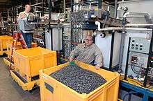
In the 1960s the froth flotation technique was adapted for deinking recycled paper.
The success of the process is evinced by the number of claimants as "discoverers" of flotation. In 1961, American engineers celebrated "50 years of flotation" and enshrined James Hyde and his Butte & Superior mill. In 1977, German engineers celebrated the "hundredth anniversary of flotation" based on the brothers Bessel patent of 1877. The historic Glasdir copper mine site advertises its tours in Wales as site of the "discovery of flotation" based upon the Elmore brothers work. Recent writers, because of the interest in celebrating women in science, champion Carrie Everson of Denver as mother of the process based on her 1885 patent. Omitted from this list are the engineers, metallurgists and chemists of Minerals Separation, Ltd., which, at least in the American and Australian courts, won control of froth flotation patents as well as right of claimant as discoverers of froth flotation. But, as historian Martin Lynch writes, "Mineral Separation would eventually prevail after taking the case to the US Supreme Court [and the House of Lords], and in so doing earned for itself the cordial detestation of many in the mining world."[16]
Industries
POES
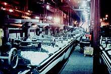
Froth flotation is a process for separating minerals from gangue by taking advantage of differences in their hydrophobicity. Hydrophobicity differences between valuable minerals and waste gangue are increased through the use of surfactants and wetting agents. The selective separation of the minerals makes processing complex (that is, mixed) ores economically feasible. The flotation process is used for the separation of a large range of sulfides, carbonates and oxides prior to further refinement. Phosphates and coal are also upgraded (purified) by flotation technology.
Prior to 1907, nearly all the copper mined in the US came from underground vein deposits, averaging 2.5 percent copper.[17] By 1991, the average grade of copper ore mined in the US had fallen to only 0.6 percent.[17]
Waste water treatment
The flotation process is also widely used in industrial waste water treatment plants, where it removes fats, oil, grease and suspended solids from waste water. These units are called dissolved air flotation (DAF) units.[18] In particular, dissolved air flotation units are used in removing oil from the wastewater effluents of oil refineries, petrochemical and chemical plants, natural gas processing plants and similar industrial facilities.
Paper recycling
Froth flotation is one of the processes used to recover recycled paper. In the paper industry this step is called deinking or just flotation. The target is to release and remove the hydrophobic contaminants from the recycled paper. The contaminants are mostly printing ink and stickies. Normally the setup is a two-stage system with 3,4 or 5 flotation cells in series.[19]
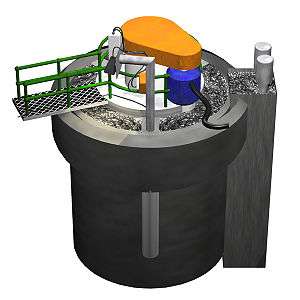
Principle of operation
Before froth flotation can work, the ore to be treated is reduced to fine particles by crushing and grinding (a process known as comminution) so that the various minerals exist as physically separate grains. This process is known as liberation. The particle sizes are typically less than 0.1 mm (100 µm), but sometimes sizes smaller than 7–10 µm are required.[20] There is a tendency for the liberation size of the minerals to decrease over time as the ore bodies with coarse mineral grains that can be separated at larger sizes are depleted and replaced by ore bodies that were formerly considered too difficult.
In the mining industry, the plants where flotation is undertaken to concentrate ore are generally known as concentrators or mills.
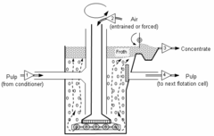
For froth flotation, the ground ore is mixed with water to form a slurry and the desired mineral is rendered hydrophobic by the addition of a surfactant or collector chemical (although some mineral surfaces are naturally hydrophobic,[21] requiring little or no addition of collector). The particular chemical depends on the nature of the mineral to be recovered and, perhaps, the natures of those that are not wanted. As an example, sodium ethyl xanthate may be added as a collector in the selective flotation of galena (lead sulfide) to separate it from sphalerite (zinc sulfide). This slurry (more properly called the pulp) of hydrophobic particles and hydrophilic particles is then introduced to tanks known as flotation cells that are aerated to produce bubbles. The hydrophobic particles attach to the air bubbles, which rise to the surface, forming a froth.[22] The froth is removed from the cell, producing a concentrate ("con") of the target mineral.
Frothing agents, known as frothers, may be introduced to the pulp to promote the formation of a stable froth on top of the flotation cell.
The minerals that do not float into the froth are referred to as the flotation tailings or flotation tails. These tailings may also be subjected to further stages of flotation to recover the valuable particles that did not float the first time. This is known as scavenging. The final tailings after scavenging are normally pumped for disposal as mine fill or to tailings disposal facilities for long-term storage.
Froth flotation efficiency is determined by a series of probabilities: those of particle–bubble contact, particle–bubble attachment, transport between the pulp and the froth, and froth collection into the product launder.[23] In a conventional mechanically-agitated cell, the void fraction (i.e. volume occupied by air bubbles) is low (5 to 10 percent) and the bubble size is usually greater than 1 mm.[24] This results in a relatively low interfacial area and a low probability of particle–bubble contact.[24] Consequently, several cells in series are required to increase the particle residence time, thus increasing the probability of particle–bubble contact.[24]
Flotation is normally undertaken in several stages to maximize the recovery of the target mineral or minerals and the concentration of those minerals in the concentrate, while minimizing the energy input.[25]
Flotation stages
Roughing
The first stage is called roughing, which produces a rougher concentrate. The objective is to remove the maximum amount of the valuable mineral at as coarse a particle size as practical.[25] The finer an ore is ground, the greater the energy that is required, so it makes sense to fine grind only those particles that need fine grinding.[25] Complete liberation is not required for rougher flotation, only sufficient liberation to release enough gangue from the valuable mineral to get a high recovery.[25]
The primary objective of roughing is to recover as much of the valuable minerals as possible, with less emphasis on the quality of the concentrate produced.
In some concentrators, there may be a preflotation step that precedes roughing.[26] This is done when there are some undesirable materials, such as organic carbon, that readily float.[26] They are removed first to avoid them floating during roughing (and thus contaminating the rougher concentrate).
Cleaning
The rougher concentrate is normally subjected to further stages of flotation to reject more of the undesirable minerals that also reported to the froth, in a process known as cleaning.[25] The product of cleaning is known as the cleaner concentrate or the final concentrate.
The objective of cleaning is to produce as high a concentrate grade as possible.
The rougher concentrate is often subject to further grinding (usually called regrinding) to get more complete liberation of the valuable minerals.[25] Because it is a smaller mass than that of the original ore, less energy is needed than would be necessary if the whole ore were reground.[25] Regrinding is often undertaken in specialized regrind mills, such as the IsaMill, designed to further reduce the energy consumed during regrinding to finer sizes.
Scavenging
The rougher flotation step is often followed by a scavenger flotation step that is applied to the rougher tailings. The objective is to recover any of the target minerals that were not recovered during the initial roughing stage. This might be achieved by changing the flotation conditions to make them more rigorous than the initial roughing, or there might be some secondary grinding to provide further liberation.
The concentrate from the rougher scavengers could be returned to the rougher feed for refloating or sent to special cleaner cells.
Similarly, the cleaning step may also be followed by a scavenging step performed on the cleaner tailings.
Science of flotation
To be effective on a given ore slurry, the collectors are chosen based upon their selective wetting of the types of particles to be separated. A good collector will adsorb, physically or chemically, with one of the types of particles. This provides the thermodynamic requirement for the particles to bind to the surface of a bubble. The wetting activity of a surfactant on a particle can be quantified by measuring the contact angles that the liquid/bubble interface makes with it. Another important measure for attachment of bubbles to particles is induction time. The induction time is the time required for the particle and bubble to rupture the thin film separating the particle and bubble. This rupturing is achieved by the surface forces between the particle and bubble.
The mechanisms for the bubble-particle attachment is very complex and consists of three steps, collision, attachment and detachment. The collision is achieved by particles being within the collision tube of a bubble and this is affected by the velocity of the bubble and radius of the bubble. The collision tube corresponds to the region in which a particle will collide with the bubble, with the perimeter of the collision tube corresponding to the grazing trajectory.
The attachment of the particle to the bubble is controlled by the induction time of the particle and bubble. The particle and bubble need to bind and this occurs if the time in which the particle and bubble are in contact with each other is larger than the required induction time. This induction time is affected by the fluid viscosity, particle and bubble size and the forces between the particle and bubbles.
The detachment of a particle and bubble occurs when the force exerted by the surface tension is exceeded by shear forces and gravitational forces. These forces are complex and vary within the cell. High shear will be experienced close to the impeller of a mechanical flotation cell and mostly gravitational force in the collection and cleaning zone of a flotation column.
Significant issues of entrainment of fine particles occurs as these particles experience low collision efficiencies as well as sliming and degradation of the particle surfaces. Coarse particles show a low recovery of the valuable mineral due to the low liberation and high detachment efficiencies.
Theory
Selective adhesion
Froth flotation depends on the selective adhesion of air bubbles to mineral surfaces in a mineral/water slurry. The air bubbles will attach to more hydrophobic particles. The attachment of the bubbles to the surface is determined by the interfacial energies between the solid, liquid, and gas phases. This is determined by the Young-Dupré Equation:[27]

where:
- γlv is the surface energy of the liquid/vapor interface
- γsv is the surface energy of the solid/vapor interface
- γsl is the surface energy of the solid/liquid interface,
- θ is the contact angle, the angle formed at the junction between vapor, solid, and liquid phases.
Minerals targeted for separation may be chemically surface-modified with collectors so that they are more hydrophobic. Collectors are a type of surfactant that increase the natural hydrophobicity of the surface, increasing the separability of the hydrophobic and hydrophilic particles. Collectors either chemically bond via chemisorption to the mineral or adsorb onto the surface via physisorption.
IMFs and surface forces in bubble-particle interactions
Collision
The collision rates for fine particles (50 - 80 μm) can be accurately modeled, but there is no current theory that accurately models bubble-particle collision for particles as large as 300 μm, which are commonly used in flotation processes.[28]
For fine particles, Stokes law underestimates collision probability while the potential equation based on Surface Charge overestimates collision probability so an intermediate equation is used.[29]
It is important to know the collision rates in the system since this step precedes the adsorption where a three phase system is formed.
Adsorption (attachment)
The effectiveness of a medium to adsorb to a particle is influenced by the relationship between the surfaces of both materials. There are multiple factors that affect the efficiency of adsorption in chemical, thermodynamic, and physical domains. These factors can range from surface energy and polarity to the shape, size, and roughness of the particle. In froth flotation, adsorption is a strong consequence of surface energy, since the small particles have a high surface area to size ratio, resulting in higher energy surfaces to form attractions with adsorbates. The air bubbles must selectively adhere to the desired minerals to elevate them to the surface of the slurry while wetting the other minerals and leaving them in the aqueous slurry medium.
Particles that can be easily wetted by water are called hydrophilic, while particles that are not easily wetted by water are called hydrophobic. Hydrophobic particles have a tendency to form a separate phase in aqueous media. In froth flotation the effectiveness of an air bubble to adhere to a particle is based on how hydrophobic the particle is. Hydrophobic particles have an affinity to air bubbles, leading to adsorption. The bubble-particle combinations are elevated to the froth zone driven by buoyancy forces.[30]
The attachment of the bubbles to the particles is determined by the interfacial energies of between the solid, liquid, and vapor phases, as modeled by the Young/Dupre Equation. The interfacial energies can be based on the natural structure of the materials, or the addition of chemical treatments can improve energy compatibility.
Collectors are the main additives used to improve particle surfaces. They function as surfactants to selectively isolate and aid adsorption between the particles of interest and bubbles rising through the slurry. Common collectors used in flotation are anionic sulfur ligands, which have a bifunctional structure with an ionic portion which shares attraction with metals, and a hydrophobic portion such as a long hydrocarbon tail. These collectors coat a particle’s surface with a monolayer of non-polar substance to aid separation from the aqueous phase by decreasing the adsorbed particle solubility in water. The adsorbed ligands can form micelles around the particles and form small-particle colloids improving stability and phase separation further.
Desorption (detachment)
The adsorption of particles to bubbles is essential to separating the minerals from the slurry, but the minerals must be purified from the additives used in separation, such as the collectors, frothers, and modifiers. The product of the cleaning, or desorption process, is known as the cleaner concentrate. The detachment of a particle and bubble requires adsorption bond cleavage driven by shear forces. Depending on the flotation cell type, shear forces are applied by a variety of mechanical systems. Among the most common are impellers and mixers. Some systems combine the functionalities of these components by placing them at key locations where they can take part in multiple froth flotation mechanisms. Cleaning cells also take advantage of gravitational forces to improve separation efficiency.
Performance calculations
Relevant equations
A common quantity used to describe the collection efficiency of a froth flotation process is flotation recovery (
). This quantity incorporates the probabilities of collision and attachment of particles to gas flotation bubbles.
where:


- , which is the product of the probability of the particle being collected ( ) and the number of possible particle collisions ( )
- is particle diameter
- is bubble diameter
- is a specified height within the flotation which the recovery was calculated
- is the particle concentration


The following, are several additional mathematical methods often used to evaluate the effectiveness of froth flotation processes. These equations are more simple than the calculation for flotation recovery, as they are based solely on the amounts of inputs and outputs of the processes.[31]
For the following equations:
- is the weight percent of feed
- is the weight percent concentrate
- is the weight percent of tailings
- , , and are the metallurgical assays of the concentrate, tailings, and feed, respectively


Ratio of feed weight to concentrate weight
(unitless)


Percent of metal recovered (
) in wt%


Percent of metal lost (
) in wt%


Percent of weight recovered
in wt%


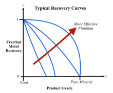
Grade-recovery curves
Grade-recovery curves are useful tools in weighing the trade-off of producing a high grade of concentrate while maintaining as low of a recovery rate as possible, two important aspects of froth flotation. These curves are developed empirically based on the individual froth flotation process of a particular plant. As the curves are shifted in the positive x-direction (to the right) and the positive y-direction (upward) the performance of the froth flotation process is regarded as improving. A disadvantage to these curves is that they can only compare the grade-recovery relations of a specific feed grade and feed rate. If a company has a variance of feed grades and rates used (an extremely common occurrence) in their froth flotation process, grade-recovery curves for every pairing of feed grade and recovery rate would have to be constructed in order to provide meaningful information to the plant.[32]
Flotation equipment
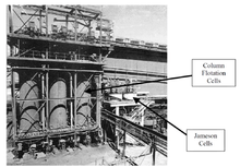
Flotation can be performed in rectangular or cylindrical mechanically agitated cells or tanks, flotation columns, Jameson Cells or deinking flotation machines. Classified by the method of air absorption manner, it is fair to state that two distinct groups of flotation equipments have arisen:pneumatic and mechanical machines. Generally pneumatic machines give a low-grade concentrate and little operating troubles.
Mechanical cells use a large mixer and diffuser mechanism at the bottom of the mixing tank to introduce air and provide mixing action. Flotation columns use air spargers to introduce air at the bottom of a tall column while introducing slurry above. The countercurrent motion of the slurry flowing down and the air flowing up provides mixing action. Mechanical cells generally have a higher throughput rate, but produce material that is of lower quality, while flotation columns generally have a low throughput rate but produce higher quality material.
The Jameson cell uses neither impellers nor spargers, instead combining the slurry with air in a downcomer where high shear creates the turbulent conditions required for bubble particle contacting.
Mechanics of flotation
The following steps are followed, following grinding to liberate the mineral particles:
- Reagent conditioning to achieve hydrophobic surface charges on the desired particles
- Collection and upward transport by bubbles in an intimate contact with air or nitrogen
- Formation of a stable froth on the surface of the flotation cell
- Separation of the mineral laden froth from the bath (flotation cell)
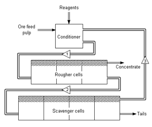
Simple flotation circuit for mineral concentration. Numbered triangles show direction of stream flow. Various flotation reagents are added to a mixture of ore and water (called pulp) in a conditioning tank. The flow rate and tank size are designed to give the minerals enough time to be activated. The conditioner pulp [1] is fed to a bank of rougher cells which remove most of the desired minerals as a concentrate. The rougher pulp [2] passes to a bank of scavenger cells where additional reagents may be added. The scavenger cell froth [3] is usually returned to the rougher cells for additional treatment, but in some cases may be sent to special cleaner cells. The scavenger pulp is usually barren enough to be discarded as tails. More complex flotation circuits have several sets of cleaner and re-cleaner cells, and intermediate re-grinding of pulp or concentrate.
Chemicals of flotation
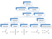
Collectors
For many ores (e.g. those of Cu, Mo, W, Ni), the collectors are anionic sulfur ligands. Particularly popular are xanthate salts, including potassium amyl xanthate (PAX), potassium isobutyl xanthate (PIBX), potassium ethyl xanthate (KEX), sodium isobutyl xanthate (SIBX), sodium isopropyl xanthate (SIPX), sodium ethyl xanthate (SEX). Other collectors include related sulfur-based ligands: dithiophosphates, dithiocarbamates. Still other classes of collectors include the thiourea thiocarbanilide. Fatty acids have also been used.
For some minerals (e.g., sylvanite for KCl), fatty amines are used as collectors.
Frothers
A variety of compounds are added to stabilize the foams. These additives include pine oil, various alcohols (methyl isobutyl carbinol (MIBC)), polyglycols, xylenol (cresylic acid).
Modifiers
A variety of other compounds are added to optimize the separation process, these additives are called modifiers. Such species do not interact directly with the mineral, but modify the physical properties of the solution.
Chemical compounds for deinking of recycled paper
- pH control: sodium silicate and sodium hydroxide
- Calcium ion source: hard water, lime or calcium chloride
- Collector: fatty acid, fatty acid emulsion, fatty acid soap and/or organo-modified siloxane[33]
Specific ore applications
Illustrative, the flotation process is used for purification of potassium chloride from sodium chloride and clay minerals. The crushed mineral is suspended in brine in the presence of fatty ammonium salts. Because the ammonium group and K+ have very similar ionic radii (ca. 0.135, 0.143 nm respectively), the ammonium centers exchange for the surface potassium sites on the particles of KCl, but not on the NaCl particles. The long alkyl chains then confer hydrophobicity, to the particles, which enable them to form foams.[34]
| Sulfide ores | ||
|
|
|
|
|
|
|
| |
| Nonsulfide ores | ||
See also
References
- ↑ G J Jameson, "Flotation cell development," in: The AusIMM Annual Conference, Broken Hill, New South Wales, 17–21 May 1992 (The Australasian Institute of Mining and Metallurgy: Melbourne, 1992), 25–31.
- ↑ Nelson, Michael (2012). ""From 10 Cubic Feet to 500 Cubic Meters--Observations on 100 Years of Flotation Technology"". Separation Technologies book edited by Courtney Young et al. Society of Mining, Metallurgy and Exploration: 539–546.
- ↑ Nguyen, Ahn (2003). Colloidal Science of Flotation. pp. 11–12. ISBN 0824747828.
- ↑ Bunyak, Dawn (2005). "The Inventor, the Patent, and Carrie Everson: Defining Success" (PDF). Mining History Journal: 9–24.
- ↑ "Wales - The birthplace of Flotation". Retrieved 2010-01-13.
- ↑ Rickard, Thomas A. (1922). Interviews with Mining Engineers. San Francisco: Mining and Scientific Press. pp. 119–131.
- ↑ Osborne, Graeme (1981). "Guillaume Daniel Delprat". Australian Dictionary of Biography. Canberra: Australian National University. Retrieved 7 June 2012.
- ↑ "Historical Note". Minerals Separation Ltd. Retrieved 2007-12-30.
- ↑ Malozemoff, Plato (March 1941). ""Operating Characteristics of Mechanical Flotation Machines,"". Engineering & Mining Journal: 45-49.
- ↑ Mouat, Jeremy (March 1996). "The Development of the Flotation Process: Technological Change and the Genesis of Modern Mining, 1898-1911". Australian Economic Review. 36 (1): 3–31.
- ↑ Callow; 1916
- ↑ Parsons, A. B. (1933). The Porphyry Coppers. New York: American Institute of Mining and Metallurgical Engineers. pp. 239–246, 446–450.
- ↑ Rickard, Thomas A. (1922). Interviews with Mining Engineers. San Francisco: Mining and Scientific Press. p. 142.
- ↑ A detailed description of the history of flotation and this process can be found in Callows "Notes on Flotation" found in the Transactions of the American Institute of Mining Engineers; Vol 53-54, originally presented in New York in February 1916.
- ↑ Gaudin,, A. M. (1932). Flotation. New York: McGraw-Hill. pp. passim.
- ↑ Lynch, Martin (2002). Mining in World History. London: Reaktion Press. p. 208. ISBN 978-1-86189-173-0.
- 1 2 Wills, B A; Atkinson, K (1991). "The development of minerals engineering in the 20th Century". Minerals Engineering. 4: 643–652. doi:10.1016/0892-6875(91)90054-y.
- ↑ Beychok, Milton R. (1967). Aqueous Wastes from Petroleum and Petrochemical Plants (1st ed.). John Wiley & Sons Ltd. LCCN 67019834.
- ↑ Voith EcoCell flotation plant "Archived copy" (PDF). Archived from the original (PDF) on 2009-08-24. Retrieved 2009-01-08.
- ↑ D N Nihill, C M Stewart and P Bowen, "The McArthur River mine—the first years of operation," in: AusIMM ’98 – The Mining Cycle, Mount Isa, 19–23 April 1998 (The Australasian Institute of Mining and Metallurgy: Melbourne, 1998), 73–82.
- ↑ E V Manlapig, C Green, J W Parkinson and A S Murphy, "The technology and economic incentives for recovering coal from tailings impoundments," SME Annual Meeting, Denver, Colorado, 26–28 February 2001, Preprint 01-70 (Society of Mining, Metallurgy and Exploration: Littleton, Colorado, 2001).
- 1 2 Williams, T. "The story of Lin Ma Hang lead mine, 1915-1962". Geological Society of Hong Kong Newsletter. 9: 3–27.
|access-date=requires|url=(help) - ↑ B W Atkinson, C J Conway and G J Jameson, "Fundamentals of Jameson Cell operation including size–yield response," in: Sixth Australian Coal Preparation Conference, Mackay, Queensland, 6–9 September 1993 (The Australasian Institute of Mining and Metallurgy: Melbourne, 1993).
- 1 2 3 B W Atkinson, C J Conway and G J Jameson, "High-efficiency flotation of coarse and fine coal," in: High-efficiency Coal Preparation: An International Symposium, (Society of Mining, Metallurgy and Exploration: Littleton, Colorado, 1995).
- 1 2 3 4 5 6 7 J Pease, "Increasing the energy efficiency of grinding," Presented at: Crushing and Grinding, Brisbane, September 2007. Accessed 24 May 2013.
- 1 2 T Smith, D Lin, B Lacouture and G Anderson, "Removal of organic carbon with a Jameson Cell at Red Dog Mine," in: Proceedings of the 40th Annual Meeting of the Canadian Mineral Processors, Ottawa, Ontario, 22–24 January 2008. Accessed 6 June 2013.
- ↑ Kawatra, S.K. "Flotation Fundamentals" (PDF). MTU Chemistry. Retrieved 8 June 2015.
- ↑ Nguyen, Anh V (12 June 1996). "On modelling of bubble–particle attachment probability in flotation". International Journal of Mineral Processing. 53: 225–249. doi:10.1016/S0301-7516(97)00073-2.
- ↑ Shahbazi, B. "Bubble–particle collision and attachment probability on fine particles flotation". Chemical Engineering and Processing: Process Intensification. 49: 622–627. doi:10.1016/j.cep.2010.04.009.
- ↑ Kawatra, S.K. "Flotation Fundamentals" (PDF). MTU Chemistry. Retrieved 8 June 2015.
- ↑ Kawatra, S. K. "Froth Flotation – Fundamental Principles." (n.d.): n. pag. Web.
- ↑ Neethling, S.j., and J.j. Cilliers. "Grade-recovery Curves: A New Approach for Analysis of and Predicting from Plant Data." Minerals Engineering 36-38 (2012): 105-10. Web.
- ↑ WO 011717, Nellesen, Bernhard & Christina Northfleet, "METHOD OF DEINKING", published 05.02.2004
- ↑ Elizabeth R. Burkhardt "Potassium and Potassium Alloys" in Ullmann's Encyclopedia of Industrial Chemistry, Wiley-VCH, 2006. doi:10.1002/14356007.a22_031.pub2
- ↑ Sebenik, Roger F. et al. (2005) "Molybdenum and Molybdenum Compounds" in Ullmann's Encyclopedia of Chemical Technology. Wiley-VCH, Weinheim. doi: 10.1002/14356007.a16_655
Further reading
- Froth Flotation: A Century of Innovation, by Maurice C. Fuerstenau et al. 2007, SME, 891 pp. ISBN 978-0873352529. Google Books preview
| Wikimedia Commons has media related to Flotation. |
