Fresnel equations

_2.jpg)
The Fresnel equations (or Fresnel coefficients) describe the reflection and transmission of light (or electromagnetic radiation in general) when incident on an interface between different optical media. They were deduced by Augustin-Jean Fresnel (/freɪˈnɛl/) who was the first to understand that light is a transverse wave, even though no one realized that the "vibrations" of the wave were electric and magnetic fields. For the first time, polarization could be understood quantitatively, as Fresnel's equations correctly predicted the differing behaviour of waves of the s and p polarizations incident upon a material interface.
Overview
When light strikes the interface of a medium of a given refractive index, n1 and a second medium with refractive index, n2, both reflection and refraction of the light may occur. The Fresnel equations describe the ratio of the reflected and transmitted electric fields to that of the incident beam (the waves' magnetic fields can also be related using similar coefficients). Since these are complex ratios, they describe not only the relative amplitude, but phase shifts between the waves.
The equations assume the interface between the media is flat and that the media are homogeneous and isotropic.[1] The incident light is assumed to be a plane wave, which is sufficient to solve any problem since any incident light field can be decomposed into plane waves and polarizations.
S and P polarizations
There are two sets of Fresnel coefficients for two different linear polarization components of the incident wave. Since any polarization state can be resolved into a combination of two orthogonal linear polarizations, this is sufficient for any problem. Likewise, unpolarized (or "randomly polarized") light has an equal amount of power in each of two linear polarizations.
The s polarization refers to polarization of a wave's electric field normal to the plane of incidence (the Z direction in the derivation below); then the magnetic field is in the plane of incidence. P polarization refers to polarization of the electric field in the plane of incidence (along the X and Y directions in the derivation below); then the magnetic field is normal to the plane of incidence.
Although the reflectivity and transmission are dependent on polarization, at normal incidence (θ=0) there is no distinction between them so all polarization states are governed by a single set of Fresnel coefficients (and also another special case is mentioned below in which that is true).
Power (intensity) reflection and transmission coefficients

In the diagram on the right, an incident plane wave in the direction of the ray IO, strikes the interface between two media of refractive indices n1 and n2 at point O. Part of the wave is reflected in the direction OR, and part refracted in the direction OT. The angles of the incident, reflected and refracted waves make to the normal of the interface are given as θi, θr and θt, respectively.
The relationship between these angles is given by the law of reflection:

and Snell's law:

The behaviour of light striking the interface is solved by considering the electric and magnetic fields that constitute an electromagnetic wave, and the laws of electromagnetism as shown below. The ratio of waves' electric field (or magnetic field) amplitudes are supplied, but in practice one is more often interested in formulae which determine power coefficients, since power (or irradiance) is what can be directly measured at optical frequencies. The power of a wave is generally proportional to the square of the electric (or magnetic) field amplitude.
We call the fraction of the incident power that is reflected from the interface the reflectance (or "reflectivity", or "power reflection coefficient") R, and the fraction that is refracted into the second medium is called the transmittance (or "transmissivity", or "power transmission coefficient") T . Note that these are what would be measured right at each side of an interface and do not account for attenuation of a wave in an absorbing medium following transmission or reflection.[2]
The reflectance for s-polarized light is

while the reflectance for p-polarized light is

where Z1 and Z2 are the wave impedances of media 1 and 2, respectively.
We restrict our scope to non-magnetic media (i.e. materials for which μ1 = μ2 = μ0) which is typically true at optical frequencies (and most other problems)[3]. Then the wave impedances are determined solely by the refractive indices n1 and n2:

where Z0 is the impedance of free space. Making this substitution, we obtain equations using the refractive indices:


The second form of each equation is derived from the first by eliminating θt using Snell's law and trigonometric identities.
As a consequence of conservation of energy, one can find the transmitted power (or more correctly, irradiance: power per unit area) simply as the portion of the incident power that isn't reflected: [4]

and

Note that all such intensities are measured in terms of a wave's irradiance in the direction normal to the interface; this is also what is measured in typical experiments. That number could be obtained from irradiances in the direction of an incident or reflected wave (given by the magnitude of a wave's Poynting vector) multiplied by cos(θ) for a wave at an angle θ to the normal direction (or equivalently, taking the dot product of the Poynting vector with the unit vector normal to the interface). For just considering reflection, since cos(θi) = cos(θr), the ratio of reflected to incident irradiance in the wave's direction is the same as the ratio of the power flow in the normal direction, and this complication can be ignored.
Although these relationships describe the basic physics, in many practical applications one is concerned with "natural light" that can be describe as unpolarized. That means that there is an equal amount of power in the s and p polarizations, so that the effective reflectivity of the material is just the average of the two reflectivities:

For low-precision applications involving unpolarized light, such as computer graphics, rather than rigorously computing the effective reflection coefficient for each angle, Schlick's approximation is often used.
Special cases
Normal incidence
For the case of normal incidence, , and there is no distinction between s and p polarization. Thus, the reflectance simplifies to

- .

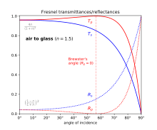
For common glass (n2 ≈ 1.5) surrounded by air (n1=1), the power reflectance at normal incidence can be seen to be about 4%, or 8% accounting for both sides of a glass pane.
Brewster's angle
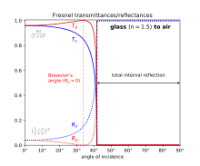
At a dielectric interface from n1 to n2, there is a particular angle of incidence at which Rp goes to zero and a p-polarised incident wave is purely refracted. This angle is known as Brewster's angle, and is around 56° for n1 = 1 and n2=1.5 (typical glass).
Total internal reflection
When light travelling in a denser medium strikes the surface of a less dense medium (i.e., n1 > n2), beyond a particular incidence angle known as the critical angle, all light is reflected and Rs = Rp = 1. This phenomenon is known as total internal reflection. Total internal reflection occurs for incidence angles for which, using Snell's law, the sine of the angle of refraction would exceed unity (whereas sin(θ) ≤ 1 for all real θ). Again assuming glass with n=1.5 surrounded by air, the critical angle is approximately 41°.
Amplitude reflection and transmission coefficients
The above practical equations relating powers (which could be measured with a photometer for instance) are derived from the actual Fresnel equations which solve the physical problem in terms of electric and magnetic field amplitudes. Those underlying equations supply generally complex-valued ratios of those amplitudes and may take several different forms, depending on formalisms used. The amplitude coefficients are usually represented by lower case r and t (whereas the power coefficients are capitalized).

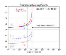
In the following, the reflection coefficient r is the ratio of the reflected wave's complex electric field amplitude to that of the incident wave. The transmission coefficient t is the ratio of the transmitted wave's electric field amplitude to that of the incident wave. We require separate formulae for the s and p polarizations. In each case we assume an incident plane wave at an angle of incidence on a plane interface, reflected at an angle , and with a transmitted wave at an angle , corresponding to the above figure. Note that in the cases of an interface into an absorbing material (where n is complex) or total internal reflection, the angle of transmission might not evaluate to a real number.


We consider the sign of a wave's electric field in relation to a wave's direction. Consequently for p polarization at normal incidence, the positive direction of electric field for an incident wave (to the left) is opposite that of a reflected wave (also to its left); for s polarization both are the same (upward). [Note 1]
Using these conventions,.[5][6]
![{\displaystyle {\begin{aligned}r_{\text{s}}&={\frac {n_{1}\cos \theta _{\text{i}}-n_{2}\cos \theta _{\text{t}}}{n_{1}\cos \theta _{\text{i}}+n_{2}\cos \theta _{\text{t}}}},\\[3pt]t_{\text{s}}&={\frac {2n_{1}\cos \theta _{\text{i}}}{n_{1}\cos \theta _{\text{i}}+n_{2}\cos \theta _{\text{t}}}},\\[3pt]r_{\text{p}}&={\frac {n_{2}\cos \theta _{\text{i}}-n_{1}\cos \theta _{\text{t}}}{n_{2}\cos \theta _{\text{i}}+n_{1}\cos \theta _{\text{t}}}},\\[3pt]t_{\text{p}}&={\frac {2n_{1}\cos \theta _{\text{i}}}{n_{2}\cos \theta _{\text{i}}+n_{1}\cos \theta _{\text{t}}}}.\end{aligned}}}](../I/m/175a7f341dbca168e50878dc6b1fdefca1d4bdf2.svg)
One can see that ts = rs + 1[7] and n2/n1tp=rp+1. One can write similar equations applying to the ratio of magnetic fields of the waves, but these are usually not required.
Because the reflected and incident waves propagate in the same medium and make the same angle with the normal to the surface, the power reflection coefficient R is just the squared magnitude of r: [8]

On the other hand, calculation of the power transmission coefficient T is less straight-forward, since the light travels in different directions in the two media. What's more, the wave impedances in the two media differ; power is only proportional to the square of the amplitude when the media's impedances are the same (as they are for the reflected wave). This results in[9]:

The factor of n2/n1 is the reciprocal of the ratio of the media's wave impedances (since we assume μ=1). The factor of cos(θt)/cos(θi) is from expressing power in the direction normal to the interface, for both the incident and transmitted waves.
In the case of total internal reflection where the power transmission T=0, t nevertheless describes the electric field (including its phase) just beyond the interface. This is an evanescent field which does not propagate as a wave (thus T=0) but has nonzero values very close to the interface. The phase shift of the reflected wave on total internal reflection can similarly be obtained from the phase angles of rp and rs (whose magnitudes are unity). These phase shifts are different for s and p waves, which is the well-known principle by which total internal reflection is used to effect polarization transformations.
Alternative forms
In the above formula for rs, if we put (Snell's law) and multiply the numerator and denominator by 1/n1 sin θt, we obtain [10][11]


If we do likewise with the formula for rp, the result is easily shown to be equivalent to [12][13]

These formulas [14][15][16] are known respectively as Fresnel's sine law and Fresnel's tangent law.[17] Although at normal incidence these expressions reduce to 0/0, one can see that they yield the correct results in the limit as θi → 0.
Multiple surfaces
When light makes multiple reflections between two or more parallel surfaces, the multiple beams of light generally interfere with one another, resulting in net transmission and reflection amplitudes that depend on the light's wavelength. The interference, however, is seen only when the surfaces are at distances comparable to or smaller than the light's coherence length, which for ordinary white light is few micrometers; it can be much larger for light from a laser.
An example of interference between reflections is the iridescent colours seen in a soap bubble or in thin oil films on water. Applications include Fabry–Pérot interferometers, antireflection coatings, and optical filters. A quantitative analysis of these effects is based on the Fresnel equations, but with additional calculations to account for interference.
The transfer-matrix method, or the recursive Rouard method [18] can be used to solve multiple-surface problems.
History
In 1808, Étienne-Louis Malus discovered that when a ray of light was reflected off a non-metallic surface at the appropriate angle, it behaved like one of the two rays emerging from a doubly-refractive calcite crystal.[19] He later coined the term polarization to describe this behavior. In 1815, the dependence of the polarizing angle on the refractive index was determined experimentally by David Brewster.[20] But the reason for that dependence was such a deep mystery that in late 1817, Thomas Young was moved to write:
[T]he great difficulty of all, which is to assign a sufficient reason for the reflection or nonreflection of a polarised ray, will probably long remain, to mortify the vanity of an ambitious philosophy, completely unresolved by any theory.[21]
In 1821, however, Augustin-Jean Fresnel derived results equivalent to his sine and tangent laws (above), by modeling light waves as transverse elastic waves with vibrations perpendicular to what had previously been called the plane of polarization. Fresnel promptly confirmed by experiment that the equations correctly predicted the direction of polarization of the reflected beam when the incident beam was polarized at 45° to the plane of incidence, for light incident from air onto glass or water; in particular, the equations gave the correct polarization at Brewster's angle.[22] The experimental confirmation was reported in a "postscript" to the work in which Fresnel first revealed his theory that light waves, including "unpolarized" waves, were purely transverse.[23]
Details of Fresnel's derivation, including the modern forms of the sine law and tangent law, were given later, in a memoir read to the French Academy of Sciences in January 1823.[24] That derivation combined conservation of energy with continuity of the tangential vibration at the interface, but failed to allow for any condition on the normal component of vibration.[25] The first derivation from electromagnetic principles was given by Hendrik Lorentz in 1875.[26]
In the same memoir of January 1823,[24] Fresnel found that for angles of incidence greater than the critical angle, his formulas for the reflection coefficients (rs and rp) gave complex values with unit magnitudes. Noting that the magnitude, as usual, represented the ratio of peak amplitudes, he guessed that the argument represented the phase shift, and verified the hypothesis experimentally.[27] The verification involved
- calculating the angle of incidence that would introduce a total phase difference of 90° between the s and p components, for various numbers of total internal reflections at that angle (generally there were two solutions),
- subjecting light to that number of total internal reflections at that angle of incidence, with an initial linear polarization at 45° to the plane of incidence, and
- checking that the final polarization was circular.[28]
Thus he finally had a quantitative theory of the Fresnel rhomb — which he had been using in experiments, in one form or another, since 1817 (see Fresnel rhomb § History).
The success of the complex reflection coefficient inspired James MacCullagh and Augustin-Louis Cauchy, beginning in 1836, to analyze reflection from metals by using the Fresnel equations with a complex refractive index.[29]
Four weeks before he presented his completed theory of total internal reflection and the rhomb, Fresnel submitted a memoir [30] in which he introduced the needed terms linear polarization, circular polarization, and elliptical polarization,[31] and in which he explained optical rotation as a species of birefringence: linearly-polarized light can be resolved into two circularly-polarized components rotating in opposite directions, and if these propagate at different speeds, the phase difference between them — hence the orientation of their linearly-polarized resultant — will vary continuously with distance.[32]
Thus Fresnel's interpretation of the complex values of his reflection coefficients marked the confluence of several streams of his research and, arguably, the essential completion of his reconstruction of physical optics on the transverse-wave hypothesis (see Augustin-Jean Fresnel).
Theory
Here we systematically derive the above relations from electromagnetic premises.
Material parameters
In order to compute meaningful Fresnel coefficients, we must assume the medium is (approximately) linear and homogeneous. If the medium is also isotropic then the four field quantities are related through multiplication by the scalar quantities ϵ and μ: B = μH and D = ϵE, where μ is the permeability of the medium and ϵ is the permittivity of the medium.
The permittivity ϵ sets the ratio of D to E. More often one refers to the relative permittivity also known as the dielectric constant ϵrel which, when multiplied by the permittivity of free space ϵ0 yields the permittivity ϵ. In optics, one usually is supplied with the index of refraction n which is just the square root of ϵrel as long as μrel =1 (the usual case):

It is possible for a material to have a magnetic polarization, though in most cases this is not true and one just assumes the relative permeability μrel=1. In general though establishes the ratio of B to H in an isotropic medium. At optical frequencies all materials have μrel=1 (except for possible metamaterials). This is usually true at lower frequencies but for the cases of ferromagnetic materials at radio/microwave frequencies such a material's μrel must be taken into account.

From the material's ϵ and μ we form two constants directly determining the form of a plane wave in that material. The index of refraction n inversely affects the phase velocity of a plane wave and inversely affects the magnitude of the wave vector k (below):


Secondly, the wave impedance of a material defines the ratio of the magnitudes of the electric and magnetic field in a plane wave:

In free space Z takes the value of the impedance of free space:

Consequently the wave impedance can be found simply in terms of the refractive index for non-magnetic media as Z0/n or in general:


In the derivation below, we use rather the reciprocal of Z, the wave admittance Y=1/Z.
Electromagnetic plane waves
In a uniform plane sinusoidal electromagnetic wave, the electric field E has the form
-
(1)

where Ek is the (constant) complex amplitude vector, i is the imaginary unit, k is the wave vector (whose magnitude k is the angular wavenumber), r is the position vector, ω is the angular frequency, t is time, and it is understood that the real part of the expression is the physical field.[Note 2] The value of the expression is unchanged if the position r varies in a direction normal to k; hence k is normal to the wavefronts.
To advance the phase by the angle φ, we replace ωt by ωt+φ (that is, we replace −ωt by −ωt−φ), with the result that the (complex) field is multiplied by e−iφ. So a phase advance is equivalent to multiplication by a complex constant with a negative argument. This becomes more obvious when the field (1) is factored as Ek eik⋅re−iωt, where the last factor contains the time-dependence. That factor also implies that differentiation w.r.t. time corresponds to multiplication by −iω. [Note 3]
If ℓ is the component of r in the direction of k , the field (1) can be written Ek ei(kℓ−ωt). If the argument of ei(⋯) is to be constant, ℓ must increase at the velocity known as the phase velocity. This in turn is equal to where c is the speed of light in vacuum and n is the refractive index. Solving for k gives


-
.
(2)

As usual, we drop the time-dependent factor e−iωt which is understood to multiply every complex field quantity. Then Faraday's law and the Maxwell-Ampère law respectively reduce to [33]

Using the material properties discussed above, we can eliminate B and D to obtain equations in only E and H:

In the case of real material parameters ε and μ (true in a lossless dielectric), k , E , H form a right-handed orthogonal triad. Thus the above vector multiplications can be reduced to scalar multiplication. Solving the two equations for consistency, we find again the original constraint on the magnitude of k and the refractive index n:

-
(4)

which determines the phase velocity .

And using the two equations, dividing the magnitude of H by E again yields the wave admittance (reciprocal of the wave impedance):
-
.
(5)

The wave vectors
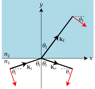
In Cartesian coordinates (x, y,z), let the region y < 0 have refractive index n1 , intrinsic impedance Y1 , etc., and let the region y > 0 have refractive index n2 , intrinsic impedance Y2 , etc. Then the xz plane is the interface, and the y axis is normal to the interface (see diagram). Let i and j (in bold roman type) be the unit vectors in the x and y directions, respectively. Let the plane of incidence be the xy plane (the plane of the page), with the angle of incidence θi measured from j towards i. Let the angle of refraction, measured in the same sense, be θt , where the subscript t stands for transmitted (reserving r for reflected).
In the absence of Doppler shifts, ω does not change on reflection or refraction. Hence, by (2), the magnitude of the wave vector is proportional to the refractive index.
So, for a given ω, if we redefine k as the magnitude of the wave vector in the reference medium (for which n =1), then the wave vector has magnitude n1k in the first medium (region y < 0 in the diagram) and magnitude n2k in the second medium. From the magnitudes and the geometry, we find that the wave vectors are
![{\displaystyle {\begin{aligned}\mathbf {k} _{\text{i}}&=n_{1}k(\mathbf {i} \sin \theta _{\text{i}}+\mathbf {j} \cos \theta _{\text{i}})\\[.5ex]\mathbf {k} _{\text{r}}&=n_{1}k(\mathbf {i} \sin \theta _{\text{i}}-\mathbf {j} \cos \theta _{\text{i}})\\[.5ex]\mathbf {k} _{\text{t}}&=n_{2}k(\mathbf {i} \sin \theta _{\text{t}}+\mathbf {j} \cos \theta _{\text{t}})\\&=k(\mathbf {i} \,n_{1}\sin \theta _{\text{i}}+\mathbf {j} \,n_{2}\cos \theta _{\text{t}})\,,\end{aligned}}}](../I/m/1abd2444be26a20f2df688f85bc0565920b5df5c.svg)
where the last step uses Snell's law. The corresponding dot products in the phasor form (3) are
-
(6)

Hence:
-
At .
(7)

The s components
For the s polarization, the E field is parallel to the z axis and may therefore be described by its component in the z direction. Let the reflection and transmission coefficients be rs and ts , respectively. Then, if the incident E field is taken to have unit amplitude, the phasor form (3) of its z component is
-
(8)

and the reflected and transmitted fields, in the same form, are
-
(9)

Under the sign convention used in this article, a positive reflection or transmission coefficient is one that preserves the direction of the transverse field, meaning the field normal to the plane of incidence. For the s (TE) polarization, that means the E field. If the incident, reflected, and transmitted E fields (in the above equations) are in the z direction ("out of the page"), then the respective H fields are in the directions of the red arrows, since k , E , H form a right-handed orthogonal triad. The H fields may therefore be described by their components in the directions of those arrows, denoted by Hi , Hr, Ht . Then, since H = YE,
-
(10)

At the interface, by the usual interface conditions for electromagnetic fields, the tangential components of the E and H fields must be continuous; that is,
-
.
(11)

When we substitute from equations (8) to (10) and then from (7), the exponential factors cancel out, so that the interface conditions reduce to the simultaneous equations
-
(12)

which are easily solved for rs and ts, yielding
-
(13)

and
-
.
(14)

At normal incidence (θi = θt = 0), indicated by an additional subscript 0, these results become
-
(15)

and
-
.
(16)

At grazing incidence (θi → 90°), we have cos θi → 0, hence rs → −1 and ts → 0.
The p components
For the p polarization, the incident, reflected, and transmitted E fields are parallel to the red arrows and may therefore be described by their components in the directions of those arrows. Let those components be Ei , Er, Et (redefining the symbols for the new context). Let the reflection and transmission coefficients be rp and tp. Then, if the incident E field is taken to have unit amplitude, we have
-
(17)

If the E fields are in the directions of the red arrows, then, in order for k , E , H to form a right-handed orthogonal triad, the respective H fields must be in the −z direction ("into the page") and may therefore be described by their components in that direction. This is consistent with the adopted sign convention, namely that a positive reflection or transmission coefficient is one that preserves the direction of the transverse field (the H field in the case of the p (TM) polarization). The agreement of the other field with the red arrows reveals an alternative definition of the sign convention: that a positive reflection or transmission coefficient is one for which the field vector in the plane of incidence points towards the same medium before and after reflection or transmission.[34]
So, for the incident, reflected, and transmitted H fields, let the respective components in the −z direction be Hi , Hr, Ht . Then, since H = YE,
-
(18)

At the interface, the tangential components of the E and H fields must be continuous; that is,
-
.
(19)

When we substitute from equations (17) and (18) and then from (7), the exponential factors again cancel out, so that the interface conditions reduce to
-
(20)

Solving for rp and tp, we find
-
(21)

and
-
.
(22)

At normal incidence (θi = θt = 0), indicated by an additional subscript 0, these results become
-
(23)

and
-
.
(24)

At grazing incidence (θi → 90°), we again have cos θi → 0, hence rp → −1 and tp → 0.
Comparing (23) and (24) with (15) and (16), we see that at normal incidence, under the adopted sign convention, the transmission coefficients for the two polarizations are equal, whereas the reflection coefficients have equal magnitudes but opposite signs. While this clash of signs is a disadvantage of the convention, the attendant advantage is that the signs agree at grazing incidence.
Power ratios (reflectivity and transmissivity)
The Poynting vector for a plane wave is a vector whose component in any direction is the irradiance (power per unit area) of that wave on a surface perpendicular to that direction. The Poynting vector is 1/2Re{E × H∗} where E and H are due only to the wave in question. Inside a lossless dielectric (the usual case) E and H are in phase and at right angles, and at right angles to the wave vector k, so for s polarization, using the Z and X-Y components of E and H respectively (or the X-Y and -Z components of E and H for p polarization) the irradiance in the direction of k is just given by EH/2 or E2/2Z in a medium of characteristic impedance Z=1/Y. To compute the irradiance in the direction normal to the interface, as we shall require in the definition of the power transmission coefficient, one could use only the X component (rather than the full X-Y component) of H or E; or equivalently just multiply EH/2 by the proper geometric factor, obtaining (E2/2Z) cos θ,.
From equations (13) and (21), taking squared magnitudes, we find that the reflectivity (ratio of reflected power to incident power) is
-
(25)

for the s polarization, and
-
(26)

for the p polarization. Note that when comparing the powers of two such waves in the same medium and with the same cos θ, the impedance and geometric factors mentioned above are identical and cancel out. They are thus not taken into account, as they must be in computing the power transmission, below.
The simplest way to obtain the power transmission coefficient (or transmissivity , ratio of transmitted power to incident power in the direction normal to the interface, Y) is to simply use R+T=1 due to conservation of energy. We find for the two polarization cases:
-
(27)

for the s polarization, and
-
(28)

for the p polarization.
In the case of an interface between two lossless media (real ε and μ >0) one can obtain these results directly using the squared magnitude of the amplitude transmission coefficients we found earlier in equations (14) and (22). Then, as noted above, to find the Poynting vector in the Y direction, each power must be multiplied by the geometric factor cos θ and divided by the wave impedance Z. Applying these corrections to each wave we obtain two ratios multiplying the square of the amplitude transmission coefficient:
-
(27)

for the s polarization, and
-
(28)

for the p polarization. In addition to only applying to lossless dielectrics, the latter equations are valid only at incidence angles smaller than the critical angle (beyond which T=0 of course!).
Equal refractive indices
From equations (4) and (5), we see that two dissimilar media will have the same refractive index, but different admittances, if the ratio of their permeabilities is the inverse of the ratio of their permittivities. It that unusual situation we have θt = θi (that is, the transmitted ray is undeviated), so that the cosines in equations (13), (14), (21), (22), and (25) to (28) cancel out, and all the reflection and transmission ratios become independent of the angle of incidence; in other words, the ratios for normal incidence become applicable to all angles of incidence.
Non-magnetic media
Since the Fresnel equations were developed for optics, they are usually given for non-magnetic materials. Since
- .

(from dividing (4) by (5)) we can substitute the vacuum permeability μ0 for μ, so that
- .

When we make these substitutions in equations (13) to (16) and equations (21) to (26), the factor cμ0 cancels out, with the result that the admittances are simply proportional to the corresponding refractive indices. Thus we obtain
-
(29)

-
(30)

-
(33)

-
(34)

For the case of normal incidence these reduce to:
-
(31)

-
(32)

-
(35)

-
(36)

The power reflection coefficients become:
-
(37)

-
.
(38)

The power transmissions can then be found from T=1-R.
Brewster's angle
For equal permeabilities (e.g., non-magnetic media), if θi and θt are complementary, we can substitute sin θt for cos θi, and sin θi for cos θt, so that the numerator in equation (33) becomes n2sin θt − n1sin θi, which is zero (by Snell's law). Hence rp = 0 and only the s-polarized component is reflected. This is what happens at the Brewster angle). Substituting cos θi for sin θt in Snell's law, we readily obtain
-
(39)

for Brewster's angle.
Equal permittivities?
Although not encountered in practice, we can consider the case of refractive indices due only to magnetic permeability of the media, with εrel=1. From equations (4) and (5), we see that if ϵ is fixed instead of μ, then n becomes proportional to Z, not to Y. Hence, if all the reflection and transmission ratios are expressed in terms of refractive indices, the subscripts will match the impedance forms rather than the admittance forms; that is, the subscripts 1 and 2 in equations (29) to (38) will be interchanged. Hence, in (29) and (33), the expressions for rs and rp in terms of refractive indices will be interchanged, so that Brewster's angle (39) will give rs = 0 instead of rp = 0, and any beam reflected at that angle will be p-polarized instead of s-polarized.[35] Similarly, Fresnel's sine law will apply to the p polarization instead of the s polarization, and his tangent law to the s polarization instead of the p polarization.
This switch of polarizations has an analog in the old mechanical theory of light waves. One could predict reflection coefficients that agreed with observation by supposing (like Fresnel) that different refractive indices were due to different densities and that the vibrations were normal to what was then called the plane of polarization, or by supposing (like MacCullagh and Neumann) that different refractive indices were due to different elasticities and that the vibrations were parallel to that plane.[36] Thus the condition of equal permittivities and unequal permeabilities, although not seen in practice, is of some historical interest.
See also
- Polarization mixing
- Index-matching material
- Field and power quantities
- Fresnel rhomb, Fresnel's apparatus to produce circularly polarised light
- Specular reflection
- Schlick's approximation
- Snell's window
- X-ray reflectivity
- Plane of incidence
- Reflections of signals on conducting lines
Notes
- ↑ Some authors use the opposite sign convention for rp, so that rp is positive when the incoming and reflected magnetic fields are anti-parallel, and negative when they are parallel. This latter convention has the convenient advantage that the s and p sign conventions are the same at normal incidence. However, either convention, when used consistently, gives the right answers.
- ↑ The above form (1) is typically used by physicists. Electrical engineers typically prefer the form Ek ej(ωt−k⋅r); that is, they not only use j instead of i for the imaginary unit, but also change the sign of the exponent, with the result that the whole expression is replaced by its complex conjugate, leaving the real part unchanged [Cf. (e.g.) Collin, 1966, p. 41, eq.(2.81)]. The electrical engineers' form and the formulas derived therefrom may be converted to the physicists' convention by substituting −i for j.
- ↑ In the electrical engineering convention, the time-dependent factor is ejωt, so that a phase advance corresponds to multiplication by a complex constant with a positive argument, and differentiation w.r.t. time corresponds to multiplication by +jω. This appendix uses the physics convention, whose time-dependent factor is e−iωt. Although the imaginary unit does not appear explicitly in the results given here, the chosen time-dependent factor affects the interpretation of any results that turn out to be complex.
References
- ↑ Born & Wolf, 1970, p. 38.
- ↑ Hecht, 1987, p. 100.
- ↑ http://www.tandfonline.com/doi/book/10.1081/E-EOE
- ↑ Hecht, 1987, p. 102.
- ↑ Lecture notes by Bo Sernelius, main site, see especially Lecture 12.
- ↑ Born & Wolf, 1970, p. 40, eqs. (20), (21).
- ↑ Hecht, 2002, p. 116, eqs. (4.49), (4.50).
- ↑ Hecht, 2002, p. 120, eq. (4.56).
- ↑ Hecht, 2002, p. 120, eq. (4.57).
- ↑ Fresnel, 1866, p. 773.
- ↑ Hecht, 2002, p. 115, eq. (4.42).
- ↑ Fresnel, 1866, p. 757.
- ↑ Hecht, 2002, p. 115, eq. (4.43).
- ↑ E. Verdet, in Fresnel, 1866, p. 789n.
- ↑ Born & Wolf, 1970, p. 40, eqs. (21a).
- ↑ Jenkins & White, 1976, p. 524, eqs. (25a).
- ↑ Whittaker, 1910, p. 134; Darrigol, 2012, p.213.
- ↑ Heavens, O. S. (1955). Optical Properties of Thin Films. Academic Press. chapt. 4.
- ↑ Darrigol, 2012, pp. 191–2.
- ↑ D. Brewster, "On the laws which regulate the polarisation of light by reflexion from transparent bodies", Philosophical Transactions of the Royal Society, vol. 105, pp. 125–59, read 16 March 1815.
- ↑ T. Young, "Chromatics" (written Sep.– Oct.1817), Supplement to the Fourth, Fifth, and Sixth Editions of the Encyclopædia Britannica, vol. 3 (first half, issued February 1818), pp. 141–63, concluding sentence.
- ↑ Buchwald, 1989, pp. 390–91; Fresnel, 1866, pp. 646–8.
- ↑ A. Fresnel, "Note sur le calcul des teintes que la polarisation développe dans les lames cristallisées" ("Note on the calculation of hues that polarization develops in crystalline laminae"), Annales de Chimie et de Physique, vol. 17, pp. 102–12 (May 1821), 167–96 (June 1821), 312–16 ("Postscript", July 1821); reprinted in Fresnel, 1866, pp. 609–48.
- 1 2 A. Fresnel, "Mémoire sur la loi des modifications que la réflexion imprime à la lumière polarisée" ("Memoir on the law of the modifications that reflection impresses on polarized light"), read 7 January 1823; reprinted in Fresnel, 1866, pp. 767–99 (full text, published 1831), pp. 753–62 (extract, published 1823). See especially pp. 773 (sine law), 757 (tangent law), 760–61 and 792–6 (angles of total internal reflection for given phase differences).
- ↑ Buchwald, 1989, pp. 391–3; Whittaker, 1910, pp. 133–5.
- ↑ Buchwald, 1989, p. 392.
- ↑ Lloyd, 1834, pp. 369–70; Buchwald, 1989, pp. 393–4, 453; Fresnel, 1866, pp. 781–96.
- ↑ Fresnel, 1866, pp. 760–61, 792–6; Whewell, 1857, p. 359.
- ↑ Whittaker, 1910, pp. 177–9.
- ↑ A. Fresnel, "Mémoire sur la double réfraction que les rayons lumineux éprouvent en traversant les aiguilles de cristal de roche suivant les directions parallèles à l'axe" ("Memoir on the double refraction that light rays undergo in traversing the needles of rock crystal [quartz] in directions parallel to the axis"), signed & submitted 9 December 1822; reprinted in Fresnel, 1866, pp. 731–51 (full text, published 1825), pp. 719–29 (extract, published 1823). On the publication dates, see also Buchwald, 1989, p. 462, ref. 1822b.
- ↑ Buchwald, 1989, pp. 230–31; Fresnel, 1866, p. 744.
- ↑ Buchwald, 1989, p. 442; Fresnel, 1866, pp. 737–9, 749. Cf. Whewell, 1857, pp. 356–8; Jenkins & White, 1976, pp. 589–90.
- ↑ Compare M.V. Berry and M.R. Jeffrey, "Conical diffraction: Hamilton's diabolical point at the heart of crystal optics", in E. Wolf (ed.), Progress in Optics, vol. 50, Amsterdam: Elsevier, 2007, pp. 13–50, at p. 18, eq.(2.2).
- ↑ This agrees with Born & Wolf, 1970, p. 38, Fig. 1.10.
- ↑ More general Brewster angles, for which the angles of incidence and refraction are not necessarily complementary, are discussed in C.L. Giles and W.J. Wild, "Brewster angles for magnetic media", International Journal of Infrared and Millimeter Waves, vol. 6, no.3 (March 1985), pp. 187–97.
- ↑ Whittaker, 1910, pp. 133, 148–9; Darrigol, 2012, pp. 212, 229–31.
- M. Born and E. Wolf, 1970, Principles of Optics, 4th Ed., Oxford: Pergamon Press.
- J.Z. Buchwald, 1989, The Rise of the Wave Theory of Light: Optical Theory and Experiment in the Early Nineteenth Century, University of Chicago Press, ISBN 0-226-07886-8.
- R.E. Collin, 1966, Foundations for Microwave Engineering, Tokyo: McGraw-Hill.
- O. Darrigol, 2012, A History of Optics: From Greek Antiquity to the Nineteenth Century, Oxford, ISBN 978-0-19-964437-7.
- A. Fresnel, 1866 (ed. H. de Senarmont, E. Verdet, and L. Fresnel), Oeuvres complètes d'Augustin Fresnel, Paris: Imprimerie Impériale (3 vols., 1866–70), vol. 1 (1866).
- E. Hecht, 1987, Optics, 2nd Ed., Addison Wesley, ISBN 0-201-11609-X.
- E. Hecht, 2002, Optics, 4th Ed., Addison Wesley, ISBN 0-321-18878-0.
- F.A. Jenkins and H.E. White, 1976, Fundamentals of Optics, 4th Ed., New York: McGraw-Hill, ISBN 0-07-032330-5.
- H. Lloyd, 1834, "Report on the progress and present state of physical optics", Report of the Fourth Meeting of the British Association for the Advancement of Science (held at Edinburgh in 1834), London: J. Murray, 1835, pp. 295–413.
- W. Whewell, 1857, History of the Inductive Sciences: From the Earliest to the Present Time, 3rd Ed., London: J.W. Parker & Son, vol. 2.
- E.T. Whittaker, 1910, A History of the Theories of Aether and Electricity: From the Age of Descartes to the Close of the Nineteenth Century, London: Longmans, Green, & Co.
Further reading
- Woan, G. (2010). The Cambridge Handbook of Physics Formulas. Cambridge University Press. ISBN 978-0-521-57507-2.
- Griffiths, David J. (2007). Introduction to Electrodynamics (3rd ed.). Pearson Education. ISBN 81-7758-293-3.
- Band, Y. B. (2010). Light and Matter: Electromagnetism, Optics, Spectroscopy and Lasers. John Wiley & Sons. ISBN 978-0-471-89931-0.
- Kenyon, I. R. (2008). The Light Fantastic – Introduction to Classic and Quantum Optics. Oxford University Press. ISBN 978-0-19-856646-5.
- Encyclopaedia of Physics (2nd Edition), R.G. Lerner, G.L. Trigg, VHC publishers, 1991, ISBN (Verlagsgesellschaft) 3-527-26954-1, ISBN (VHC Inc.) 0-89573-752-3
- McGraw Hill Encyclopaedia of Physics (2nd Edition), C.B. Parker, 1994, ISBN 0-07-051400-3
External links
- Fresnel Equations – Wolfram.
- Fresnel equations calculator
- FreeSnell – Free software computes the optical properties of multilayer materials.
- Thinfilm – Web interface for calculating optical properties of thin films and multilayer materials (reflection & transmission coefficients, ellipsometric parameters Psi & Delta).
- Simple web interface for calculating single-interface reflection and refraction angles and strengths.
- Reflection and transmittance for two dielectrics – Mathematica interactive webpage that shows the relations between index of refraction and reflection.
- A self-contained first-principles derivation of the transmission and reflection probabilities from a multilayer with complex indices of refraction.