Circular polarization
In electrodynamics, circular polarization of an electromagnetic wave is a polarization state in which, at each point, the electric field of the wave has a constant magnitude but its direction rotates with time at a steady rate in a plane perpendicular to the direction of the wave.
In electrodynamics the strength and direction of an electric field is defined by its electric field vector. In the case of a circularly polarized wave, as seen in the accompanying animation, the tip of the electric field vector, at a given point in space, describes a circle as time progresses. At any instant of time, the electric field vector of the wave describes a helix along the direction of propagation. A circularly polarized wave can be in one of two possible states, right circular polarization in which the electric field vector rotates in a right-hand sense with respect to the direction of propagation, and left circular polarization in which the vector rotates in a left-hand sense.
Circular polarization is a limiting case of the more general condition of elliptical polarization. The other special case is the easier-to-understand linear polarization.
The phenomenon of polarization arises as a consequence of the fact that light behaves as a two-dimensional transverse wave.
General description

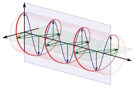
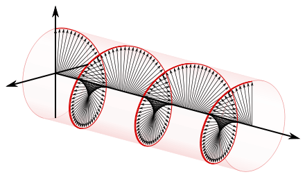
On the right is an illustration of the electric field vectors of a circularly polarized electromagnetic wave.[1] The electric field vectors have a constant magnitude but their direction changes in a rotary manner. Given that this is a plane wave, each vector represents the magnitude and direction of the electric field for an entire plane that is perpendicular to the axis. Specifically, given that this is a circularly polarized plane wave, these vectors indicate that the electric field, from plane to plane, has a constant strength while its direction steadily rotates. Refer to these two images in the plane wave article to better appreciate this. This light is considered to be right-hand, clockwise circularly polarized if viewed by the receiver. Since this is an electromagnetic wave each electric field vector has a corresponding, but not illustrated, magnetic field vector that is at a right angle to the electric field vector and proportional in magnitude to it. As a result, the magnetic field vectors would trace out a second helix if displayed.
Circular polarization is often encountered in the field of optics and in this section, the electromagnetic wave will be simply referred to as light.
The nature of circular polarization and its relationship to other polarizations is often understood by thinking of the electric field as being divided into two components which are at right angles to each other. Refer to the second illustration on the right. The vertical component and its corresponding plane are illustrated in blue while the horizontal component and its corresponding plane are illustrated in green. Notice that the rightward (relative to the direction of travel) horizontal component leads the vertical component by one quarter of a wavelength. It is this quadrature phase relationship which creates the helix and causes the points of maximum magnitude of the vertical component to correspond with the points of zero magnitude of the horizontal component, and vice versa. The result of this alignment is that there are select vectors, corresponding to the helix, which exactly match the maxima of the vertical and horizontal components. (To minimize visual clutter these are the only helix vectors displayed.)
To appreciate how this quadrature phase shift corresponds to an electric field that rotates while maintaining a constant magnitude, imagine a dot traveling clockwise in a circle. Consider how the vertical and horizontal displacements of the dot, relative to the center of the circle, vary sinusoidally in time and are out of phase by one quarter of a cycle. The displacements are said to be out of phase by one quarter of a cycle because the horizontal maximum displacement (toward the left) is reached one quarter of a cycle before the vertical maximum displacement is reached. Now referring again to the illustration, imagine the center of the circle just described, traveling along the axis from the front to the back. The circling dot will trace out a helix with the displacement toward our viewing left, leading the vertical displacement. Just as the horizontal and vertical displacements of the rotating dot are out of phase by one quarter of a cycle in time, the magnitude of the horizontal and vertical components of the electric field are out of phase by one quarter of a wavelength.
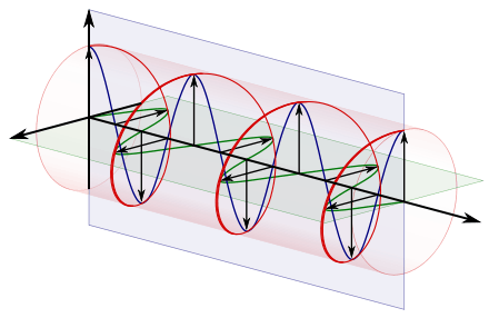
The next pair of illustrations is that of left-handed, counter-clockwise circularly polarized light when viewed by the receiver. Because it is left-handed, the rightward (relative to the direction of travel) horizontal component is now lagging the vertical component by one quarter of a wavelength rather than leading it.
Reversal of handedness by phase shift
To convert a given handedness of polarized light to the other handedness one can use a half-waveplate. A half-waveplate shifts a given component of light one half of a wavelength relative to the component to which it is orthogonal.
Reversal of handedness by reflection
The handedness of polarized light is also reversed when it is reflected off a surface at normal incidence. Upon such reflection, the rotation of the plane of polarization of the reflected light is identical to that of the incident field. However, with propagation now in the opposite direction, the same rotation direction that would be described as "right handed" for the incident beam, is "left-handed" for propagation in the reverse direction, and vice versa. Aside from the reversal of handedness, the ellipticity of polarization is also preserved (except in cases of reflection by a birefringent surface).
Note that this principle only holds strictly for light reflected at normal incidence. For instance, right circularly polarized light reflected from a dielectric surface at grazing incidence (an angle beyond the Brewster angle) will still emerge as right handed, but elliptically, polarized. Light reflected by a metal at non-normal incidence will generally have its ellipticity changed as well. Such situations may be solved by decomposing the incident circular (or other) polarization into components of linear polarization parallel and perpendicular to the plane of incidence, commonly denoted p and s respectively. The reflected components in the p and s linear polarizations are found by applying the Fresnel coefficients of reflection, which are generally different for those two linear polarizations. Only in the special case of normal incidence, where there is no distinction between p and s, are the Fresnel coefficients for the two components identical, leading to the above property.

Conversion to and from linear polarization
Circularly polarized light can be converted into linearly polarized light by passing it through a quarter-waveplate. Passing linearly polarized light through a quarter-waveplate with its axes at 45° to its polarization axis will convert it to circular polarization. In fact, this is the most common way of producing circular polarization in practice. Note that passing linearly polarized light through a quarter-waveplate at an angle other than 45° will generally produce elliptical polarization.
Left-/right-handedness conventions
Circular polarization may be referred to as right-handed or left-handed, and clockwise or anti-clockwise, depending on the direction in which the electric field vector rotates. Unfortunately, two opposing historical conventions exist.
From the point of view of the source
Using this convention, polarization is defined from the point of view of the source. When using this convention, left or right handedness is determined by pointing one's left or right thumb away from the source, in the same direction that the wave is propagating, and matching the curling of one's fingers to the direction of the spatial rotation of the field at a given point in space. When determining if the wave is clockwise or anti-clockwise circularly polarized, one again takes the point of view of the source, and while looking away from the source and in the same direction of the wave’s propagation, one observes the direction of the field’s spatial rotation.
Using this convention, the electric field vector of a right handed circularly polarized wave is as follows:

As a specific example, refer to the circularly polarized wave in the first animation. Using this convention that wave is defined as right-handed because when one points one's right thumb in the same direction of the wave’s propagation, the fingers of that hand curl in the same direction of the field’s temporal rotation. It is considered clockwise circularly polarized because from the point of view of the source, looking in the same direction of the wave’s propagation, the field rotates in the clockwise direction. The second animation is that of left-handed or anti-clockwise light using this same convention.
This convention is in conformity with the Institute of Electrical and Electronics Engineers (IEEE) standard and as a result it is generally used in the engineering community.[2][3][4]
Quantum physicists also use this convention of handedness because it is consistent with their convention of handedness for a particle’s spin.[5]
Radio astronomers also use this convention in accordance with an International Astronomical Union (IAU) resolution made in 1973.[6]
From the point of view of the receiver
In this alternative convention, polarization is defined from the point of view of the receiver. Using this convention, left or right handedness is determined by pointing one’s left or right thumb toward the source, against the direction of propagation, and then matching the curling of one's fingers to the temporal rotation of the field.
When using this convention, in contrast to the other convention, the defined handedness of the wave matches the handedness of the screw type nature of the field in space. Specifically, if one freezes a right-handed wave in time, when one curls the fingers of one’s right hand around the helix, the thumb will point in the direction which the helix progresses given that sense of rotation. Note that it is the nature of all screws and helices that it does not matter in which direction you point your thumb when determining its handedness.
When determining if the wave is clockwise or anti-clockwise circularly polarized, one again takes the point of view of the receiver and, while looking toward the source, against the direction of propagation, one observes the direction of the field’s temporal rotation.
Just as in the other convention, right-handedness corresponds to a clockwise rotation and left-handedness corresponds to an anti-clockwise rotation.
Many optics textbooks use this second convention.[7][8] It is also used by SPIE.[9]
Uses of the two conventions
As stated earlier, there is significant confusion with regards to these two conventions. As a general rule the engineering, quantum physics, and radio astronomy communities use the first convention where the wave is observed from the point of view of the source.[3][5][6] In many physics textbooks dealing with optics the second convention is used where the light is observed from the point of view of the receiver.[5][7]
To avoid confusion, it is good practice to specify “as defined from the point of view of the source” or "as defined from the point of view of the receiver" when discussing polarization matters.
The archive of the US Federal Standard 1037C proposes two contradictory conventions of handedness.[10]
FM radio
The term "circular polarization" is often used erroneously to describe mixed polarity signals used mostly in FM radio (87.5 to 108.0 MHz in the USA), where a vertical and a horizontal component are propagated simultaneously by a single or a combined array. This has the effect of producing greater penetration into buildings and difficult reception areas than a signal with just one plane of polarization. This would be an instance where the polarization would more appropriately be called random polarization because the polarization at a receiver, although constant, will vary depending on the direction from the transmitter and other factors in the transmitting antenna design. See Stokes parameters.
The term "FM radio" above refers to broadcast radio, not 2-way radio (more properly called land mobile radio), which uses vertical polarization almost exclusively.
Circular dichroism
Circular dichroism (CD) is the differential absorption of left- and right-handed circularly polarized light. Circular dichroism is the basis of a form of spectroscopy that can be used to determine the optical isomerism and secondary structure of molecules.
In general, this phenomenon will be exhibited in absorption bands of any optically active molecule. As a consequence, circular dichroism is exhibited by most biological molecules, because of the dextrorotary (e.g. some sugars) and levorotary (e.g. some amino acids) molecules they contain. Noteworthy as well is that a secondary structure will also impart a distinct CD to its respective molecules. Therefore, the alpha helix, beta sheet and random coil regions of proteins and the double helix of nucleic acids have CD spectral signatures representative of their structures.
Also, under the right conditions, even non-chiral molecules will exhibit magnetic circular dichroism, that is, circular dichroism induced by a magnetic field.
Circularly polarized luminescence
Circularly polarized luminescence (CPL) can occur when either a luminophore or an ensemble of luminophores is chiral. The extent to which emissions are polarized is quantified in the same way it is for circular dichroism, in terms of the dissymmetry factor, also sometimes referred to as the anisotropy factor. This value is given by

where corresponds to the quantum yield of left-handed circularly polarized light, and to that of right-handed light. The maximum absolute value of gem, corresponding to purely left- or right-handed circular polarization, is therefore 2. Meanwhile, the smallest absolute value that gem can achieve, corresponding to linearly polarized or unpolarized light, is zero.


Mathematical description
The classical sinusoidal plane wave solution of the electromagnetic wave equation for the electric and magnetic fields is
![{\displaystyle {\begin{aligned}\mathbf {E} (\mathbf {r} ,t)&=\left|\,\mathbf {E} \,\right|\mathrm {Re} \left\{\mathbf {Q} \left|\psi \right\rangle \exp \left[i\left(kz-\omega t\right)\right]\right\}\\\mathbf {B} (\mathbf {r} ,t)&={\hat {\mathbf {z} }}\times \mathbf {E} (\mathbf {r} ,t)\end{aligned}}}](../I/m/72e6f4e48ffd9eabf206d7664ee54e2e2ba2780c.svg)
where k is the wavenumber,

is the angular frequency of the wave, is an orthogonal matrix whose columns span the transverse x-y plane and is the speed of light.
![\mathbf{Q} = \left [ \hat{ \mathbf{x}}, \hat{\mathbf{y}} \right ]](../I/m/1c6f209c9644cf3ab69fd75e6d696bb9278c0c12.svg)


Here

is the amplitude of the field and

is the normalized Jones vector in the x-y plane.
If is rotated by radians with respect to and the x amplitude equals the y amplitude the wave is circularly polarized. The Jones vector is


where the plus sign indicates left circular polarization and the minus sign indicates right circular polarization. In the case of circular polarization, the electric field vector of constant magnitude rotates in the x-y plane.
If basis vectors are defined such that

and

then the polarization state can be written in the "R-L basis" as

where

and

Antennas
A number of different types of antenna elements can be utilized to produce circularly polarized (or nearly so) radiation; following Balanis,[11] one can use dipole elements:
"two crossed dipoles provide the two orthogonal field components... If the two dipoles are identical, the field intensity of each along zenith ... would be of the same intensity. Also, if the two dipoles were fed with a 90° degree time-phase difference (phase quadrature), the polarization along zenith would be circular... One way to obtain the 90° time-phase difference between the two orthogonal field components, radiated respectively by the two dipoles, is by feeding one of the two dipoles with a transmission line which is 1/4 wavelength longer or shorter than that of the other", p.80;
or helical elements:
"To achieve circular polarization [in axial or end-fire mode] ... the circumference C of the helix must be ... with C/wavelength = 1 near optimum, and the spacing about S = wavelength/4." p.571;
or patch elements:
"circular and elliptical polarizations can be obtained using various feed arrangements or slight modifications made to the elements... Circular polarization can be obtained if two orthogonal modes are excited with a 90° time-phase difference between them. This can be accomplished by adjusting the physical dimensions of the patch ... For a square patch element, the easiest way to excite ideally circular polarization is to feed the element at two adjacent edges ... The quadrature phase difference is obtained by feeding the element with a 90° power divider", p.859.
Quantum mechanics
In the quantum mechanical view, light is composed of photons. Polarization is a manifestation of the intrinsic angular momentum (the spin) of the photon. More specifically, in quantum mechanics the direction of spin of a photon is tied to the handedness of the circularly polarized light and the spin of a beam of photons is similar to the spin of a beam of particles, such as electrons.[12]
In nature

Only a few mechanisms in nature are known to systematically produce circularly polarized light. In 1911, Albert Abraham Michelson discovered that light reflected from the golden scarab beetle Chrysina resplendens is preferentially left-polarized. Since then, circular polarization has been measured in several other scarab beetles like Chrysina gloriosa,[13] as well as some crustaceans such as the mantis shrimp. In these cases, the underlying mechanism is the molecular-level helicity of the chitinous cuticle.[14]
The bioluminescence of the larvae of fireflies is also circularly polarized, as reported in 1980 for the species Photuris lucicrescens and Photuris versicolor. For fireflies, it is more difficult to find a microscopic explanation for the polarization, because the left and right lanterns of the larvae were found to emit polarized light of opposite senses. The authors suggest that the light begins with a linear polarization due to inhomogeneties inside aligned photocytes, and it picks up circular polarization while passing through linearly birefringent tissue.[15]
Water-air interfaces provide another source of circular polarization. Sunlight that gets scattered back up towards the surface is linearly polarized. If this light is then totally internally reflected back down, its vertical component undergoes a phase shift. To an underwater observer looking up, the faint light outside Snell's window therefore is (partially) circularly polarized.[16]
Weaker sources of circular polarization in nature include multiple scattering by linear polarizers, as in the circular polarization of starlight, and selective absorption by circularly dichroic media.
Two species of mantis shrimp have been reported to be able to detect circular polarized light.[17][18]
Starlight
The circular polarization of starlight has been observed to be a function of the linear polarization of starlight.
Starlight becomes partially linearly polarized by scattering from elongated interstellar dust grains whose long axes tend to be oriented perpendicular to the galactic magnetic field. According to the Davis–Greenstein mechanism, the grains spin rapidly with their rotation axis along the magnetic field. Light polarized along the direction of the magnetic field perpendicular to the line of sight is transmitted, while light polarized in the plane defined by the rotating grain is blocked. Thus the polarization direction can be used to map the galactic magnetic field. The degree of polarization is on the order of 1.5% for stars at 1,000 parsecs' distance.[19]
Normally, a much smaller fraction of circular polarization is found in starlight. Serkowski, Mathewson and Ford[20] measured the polarization of 180 stars in UBVR filters. They found a maximum fractional circular polarization of , in the R filter.

The explanation is that the interstellar medium is optically thin. Starlight traveling through a kiloparsec column undergoes about a magnitude of extinction, so that the optical depth ~ 1. An optical depth of 1 corresponds to a mean free path, which is the distance, on average that a photon travels before scattering from a dust grain. So on average, a starlight photon is scattered from a single interstellar grain; multiple scattering (which produces circular polarization) is much less likely. Observationally,[19] the linear polarization fraction p ~ 0.015 from a single scattering; circular polarization from multiple scattering goes as , so we expect a circularly polarized fraction of .


Light from early-type stars has very little intrinsic polarization. Kemp et al.[21] measured the optical polarization of the Sun at sensitivity of ; they found upper limits of for both (fraction of linear polarization) and (fraction of circular polarization).


The interstellar medium can produce circularly polarized (CP) light from unpolarized light by sequential scattering from elongated interstellar grains aligned in different directions. One possibility is twisted grain alignment along the line of sight due to variation in the galactic magnetic field; another is the line of sight passes through multiple clouds. For these mechanisms the maximum expected CP fraction is , where is the fraction of linearly polarized (LP) light. Kemp & Wolstencroft[22] found CP in six early-type stars (no intrinsic polarization), which they were able to attribute to the first mechanism mentioned above. In all cases, in blue light.


Martin[23] showed that the interstellar medium can convert LP light to CP by scattering from partially aligned interstellar grains having a complex index of refraction. This effect was observed for light from the Crab Nebula by Martin, Illing and Angel.[24]
An optically thick circumstellar environment can potentially produce much larger CP than the interstellar medium. Martin[23] suggested that LP light can become CP near a star by multiple scattering in an optically thick asymmetric circumstellar dust cloud. This mechanism was invoked by Bastien, Robert and Nadeau,[25] to explain the CP measured in 6 T-Tauri stars at a wavelength of 768 nm. They found a maximum CP of . Serkowski[26] measured CP of for the red supergiant NML Cygni and in the long-period variable M star VY Canis Majoris in the H band, ascribing the CP to multiple scattering in circumstellar envelopes. Chrysostomou et al.[27] found CP with q of up to 0.17 in the Orion OMC-1 star-forming region, and explained it by reflection of starlight from aligned oblate grains in the dusty nebula.


Circular polarization of zodiacal light and Milky Way diffuse galactic light was measured at wavelength of 550 nm by Wolstencroft and Kemp.[28] They found values of , which is higher than for ordinary stars, presumably because of multiple scattering from dust grains.

See also
References
- 1 2 For handedness conventions refer to the well referenced section Left/Right Handedness Conventions
- ↑ IEEE Std 149-1979 (R2008), "IEEE Standard Test Procedures for Antennas". Reaffirmed December 10, 2008, Approved December 15, 1977, IEEE-SA Standards Board. Approved October 9, 2003, American National Standards Institute. ISBN 0-471-08032-2. doi:10.1109/IEEESTD.1979.120310, sec. 11.1, p. 61."the sense of polarization, or handedness ... is called right handed (left handed) if the direction of rotation is clockwise (anti-clockwise) for an observer looking in the direction of propagation"
- 1 2 Electromagnetic Waves & Antennas – S. J. Orfanidis: Footnote p.45, "most engineering texts use the IEEE convention and most physics texts, the opposite convention."
- ↑ Electromagnetic Waves & Antennas – S. J. Orfanidis Pg 44 "Curl the fingers of your left and right hands into a fist and point both thumbs towards the direction of propagation"
- 1 2 3 Lectures on Physics Feynman (Vol. 1, ch.33-1) "If the end of the electric vector, when we look at it as the light comes straight toward us, goes around in an anti-clockwise direction, we call it right-hand circular polarization. ... Our convention for labeling left-hand and right-hand circular polarization is consistent with that which is used today for all the other particles in physics which exhibit polarization (e.g., electrons). However, in some books on optics the opposite conventions are used, so one must be careful."
- 1 2 IAU General Assembly Meeting, 1973, Commission 40 (Radio Astronomy/Radioastronomie), 8. POLARIZATION DEFINITIONS -- "A working Group chaired by Westerhout was convened to discuss the definition of polarization brightness temperatures used in the description of polarized extended objects and the galactic background. The following resolution was adopted by Commissions 25 and 40: 'RESOLVED, that the frame of reference for the Stokes parameters is that of Right Ascension and Declination with the position angle of electric-vector maximum, q, starting from North and increasing through East. Elliptical polarization is defined in conformity with the definitions of the Institute of Electrical and Electronics Engineers (IEEE Standard 211, 1969). This means that the polarization of incoming radiation, for which the position angle, q, of the electric vector, measured at a fixed point in space, increases with time, is described as right-handed and positive.'"
- 1 2 Polarization in Spectral Lines. 2004 E. Landi Degl’innocenti, M Landolfi Section 1.2 "When ... the tip of the electric field vector rotates clockwise for an observer facing the radiation source, ... (it will be considered)... positive (or righthanded) circular polarization, Our convention, ... agrees with those proposed in the classical textbooks on polarized light by Shurcliff (1952) and by Clarke and Grainger (1971). The same convention is also used, although with some few exceptions, by optical astronomers working in the field of polarimetry. Many radio astronomers, on the other hand, use the opposite convention.
- ↑ HANDBOOK OPTICS Volume I,Devices, Measurements and Properties,Michael Bass Page 272 Footnote: "Right-circularly polarized light is defined as a clockwise rotation of the electric vector when the observer is looking against the direction the wave is traveling."
- ↑ "The Polarization Ellipse". spie.org. Retrieved 13 April 2018.
- ↑ In one location it is stated..."Note 1. ... In general, the figure, i.e., polarization, is elliptical and is traced in a clockwise or anti-clockwise sense, as viewed in the direction of propagation. ... Rotation of the electric vector in a clockwise sense is designated right-hand polarization, and rotation in a anti-clockwise sense is designated left-hand polarization . " Archived 2011-03-11 at WebCite In another location it is stated... "Note 4: Circular polarization may be referred to as "right-hand" or "left-hand," depending on whether the helix describes the thread of a right-hand or left-hand screw, respectively."
- ↑ Balanis, Constantine A. "Antenna Theory – Analysis and Design", 2005, 3rd Edition, John Wiley & Sons.
- ↑ Introduction to Quantum Theory 2ED David Park Sec 2.2 Pg32 "...the polarization of a beam of light is exactly the same kind of thing as the spin of a beam of electrons, the differences of terminology reflecting only the accidents of the historical order of discovery."
- ↑ Structural Origin of Circularly Polarized Iridescence in Jeweled Beetles.
- ↑ Hegedüs, Ramón; Győző Szélb; Gábor Horváth (September 2006). "Imaging polarimetry of the circularly polarizing cuticle of scarab beetles (Coleoptera: Rutelidae, Cetoniidae)" (PDF). Vision Research. 46 (17): 2786–2797. doi:10.1016/j.visres.2006.02.007. PMID 16564066. Archived from the original (PDF) on 2011-07-21.
- ↑ Wynberg, Hans; Meijer, E.W.; Hummelen, J.C.; Dekkers, H.P.J.M.; Schippers, P.H.; Carlson, A.D. (7 August 1980). "Circular polarization observed in bioluminescence" (PDF). Nature. 286 (5773): 641–642. Bibcode:1980Natur.286..641W. doi:10.1038/286641a0. Archived from the original (PDF) on 24 July 2011.
- ↑ Horváth, Gábor; Dezsö Varjú (2003). Polarized Light in Animal Vision: Polarization Patterns in Nature. Springer. pp. 100–103. ISBN 3-540-40457-0.
- ↑ Tsyr-Huei Chiou; Sonja Kleinlogel; Tom Cronin; Roy Caldwell; Birte Loeffler; Afsheen Siddiqi; Alan Goldizen; Justin Marshall (2008). "Circular polarization vision in a stomatopod crustacean". Current Biology. 18 (6): 429–34. doi:10.1016/j.cub.2008.02.066. PMID 18356053.
- ↑ Sonja Kleinlogel; Andrew White (2008). "The secret world of shrimps: polarisation vision at its best". PLoS ONE. 3 (5): e2190. arXiv:0804.2162. Bibcode:2008PLoSO...3.2190K. doi:10.1371/journal.pone.0002190. PMC 2377063. PMID 18478095.
- 1 2 Fosalba, Pablo; Lazarian, Alex; Prunet, Simon; Tauber, Jan A. (2002). "Statistical Properties of Galactic Starlight Polarization". Astrophysical Journal. 564 (2): 722. arXiv:astro-ph/0105023. Bibcode:2002ApJ...564..762F. doi:10.1086/324297.
- ↑ Serkowski, K.; Mathewson and Ford (1975). "Wavelength dependence of interstellar polarization and ratio of total to selective extinction". Astrophysical Journal. 196: 261. Bibcode:1975ApJ...196..261S. doi:10.1086/153410.
- ↑ Kemp, J. C.; et al. (1987). "The optical polarization of the Sun measured at a sensitivity of parts in ten million". Nature. 326 (6110): 270. Bibcode:1987Natur.326..270K. doi:10.1038/326270a0.
- ↑ Kemp, James C.; Wolstencroft (1972). "Interstellar Circular Polarization: Data for Six Stars and the Wavelength Dependence". Astrophysical Journal. 176: L115. Bibcode:1972ApJ...176L.115K. doi:10.1086/181036.
- 1 2 Martin (1972). "Interstellar circular polarization". MNRAS. 159: 179. Bibcode:1972MNRAS.159..179M. doi:10.1093/mnras/159.2.179.
- ↑ Martin, P.G.; Illing, R.; Angel, J. R. P. (1972). "Discovery of interstellar circular polarization in the direction of the Crab nebula". MNRAS. 159: 191. Bibcode:1972MNRAS.159..191M. doi:10.1093/mnras/159.2.191.
- ↑ Bastein, Pierre; Robert and Nadeau (1989). "Circular polarization in T Tauri stars. II - New observations and evidence for multiple scattering". Astrophysical Journal. 339: 1089. Bibcode:1989ApJ...339.1089B. doi:10.1086/167363.
- ↑ Serkowski, K. (1973). "Infrared Circular Polarization of NML Cygni and VY Canis Majoris". Astrophysical Journal. 179: L101. Bibcode:1973ApJ...179L.101S. doi:10.1086/181126.
- ↑ Chrysostomou, Antonio; et al. (2000). "Polarimetry of young stellar objects - III. Circular polarimetry of OMC-1". MNRAS. 312: 103. Bibcode:2000MNRAS.312..103C. CiteSeerX 10.1.1.46.3044. doi:10.1046/j.1365-8711.2000.03126.x.
- ↑ Wolstencroft, Ramon D.; Kemp (1972). "Circular Polarization of the Nightsky Radiation". Astrophysical Journal. 177: L137. Bibcode:1972ApJ...177L.137W. doi:10.1086/181068.
External links
- http://www.polarization.com/beetle/beetle.html
- Article on the mantis shrimp and circular polarization
- Animation of Circular Polarization (on YouTube)
- Comparison of Circular Polarization with Linear and Elliptical Polarizations (YouTube Animation)
- Reversal of handedness of circularly polarized light by mirror. A demonstration – simple, cheap & instructive