Diving regulator
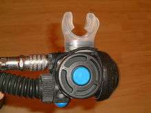
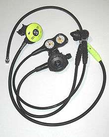 Diving regulator: First and second stages, low pressure inflator hose and submersible pressure gauge | |
| Other names | Demand valve |
|---|---|
| Uses | Reduces pressurized breathing gas to ambient pressure and delivers it to the diver |
| Inventor | Manuel Théodore Guillaumet (1838), Benoît Rouquayrol (1860) |
| Related items |
Lightweight demand helmet Full-face mask Diving cylinder Buoyancy compensator |
A diving regulator is a pressure regulator that reduces pressurized breathing gas to ambient pressure and delivers it to the diver. The gas may be air or one of a variety of specially blended breathing gases. The gas may be supplied from a scuba cylinder carried by the diver or via a hose from a compressor or high-pressure storage cylinders at the surface in surface-supplied diving. A gas pressure regulator has one or more valves in series which reduce pressure from the source, and use the downstream pressure as feedback to control the rate of flow and thereby the delivered pressure, lowering the pressure at each stage.[1]
The terms "regulator" and "demand valve" are often used interchangeably, but a demand valve is a regulator that delivers gas only while the diver is inhaling and reduces the gas pressure to ambient. In single-hose regulators, the demand valve is the second stage, which is either held in the diver's mouth by a mouthpiece or attached to the full-face mask or helmet. In twin-hose regulators the demand valve is included in the body of the regulator which is usually attached directly to the cylinder valve or manifold outlet.
A pressure-reduction regulator is used to control the delivery pressure of the gas supplied to a free-flow helmet, in which the flow is continuous, to maintain the downstream pressure which is provided by the ambient pressure of the exhaust and the flow resistance of the delivery system (mainly the umbilical) and not influenced by the breathing of the diver. Gas-reclaim systems use a third kind of regulator to control the flow of exhaled gas to the return hose. Rebreather systems may also use regulators to control the flow of fresh gas, and demand valves, known as automatic diluent valves, to maintain the volume in the breathing loop during descent.
The performance of a regulator is measured by the cracking pressure and work of breathing, and the capacity to deliver breathing gas at peak inspiratory flow rate at high ambient pressures without excessive pressure drop. For some applications the capacity to deliver high flow rates at low ambient temperatures without jamming due to freezing is important.
Purpose
The diving regulator is a mechanism which reduces the pressure of the supply of breathing gas and provides it to the diver at approximately ambient pressure. The gas may be supplied on demand, when the diver inhales, or as a constant flow past the diver inside the helmet or mask, from which the diver uses what is necessary, while the remainder goes to waste.[2]:49
The gas may be provided directly to the diver, or to a rebreather circuit, to make up for used gas and volume changes due to depth variations. Gas supply may be from a high-pressure scuba cylinder carried by the diver, or from a surface supply through a hose connected to a compressor or storage system.
Operation
Requirements
Both free-flow and demand regulators use mechanical feedback of the downstream pressure to control the opening of a valve which controls gas flow from the upstream, high-pressure side, to the downstream, low-pressure side of each stage.[3] Flow capacity must be sufficient to allow the downstream pressure to be maintained at maximum demand, and sensitivity must be appropriate to deliver maximum required flow rate with a small variation in downstream pressure, and for a large variation in supply pressure. Open circuit scuba regulators must also deliver against a variable ambient pressure. They must be robust and reliable, as they are life-support equipment which must function in a relatively hostile environment (sea water).
Mechanism
Diving regulators use mechanically operated valves.[3] In most cases there is ambient pressure feedback to both first and second stage, except where this is avoided to allow constant mass flow through an orifice in a rebreather, which requires a constant upstream pressure.
Types
Open circuit demand valve
A demand valve detects when the diver starts inhaling and supplies the diver with a breath of gas at ambient pressure. This is done by a mechanical system linking a pressure differential sensor (diaphragm) to a valve which is opened to an extent proportional to the displacement of the diaphragm difference. The pressure difference between the inside of the mouthpiece and the ambient pressure outside the diaphragm required to open the valve is known as the cracking pressure. This cracking pressure difference is usually negative but may be slightly positive on a positive pressure regulator (a regulator that maintains a pressure inside the mouthpiece, mask or helmet, which is slightly greater than the ambient pressure). Once the valve has opened, gas flow should continue at the smallest stable pressure difference reasonably practicable while the diver inhales, and should stop as soon as gas flow stops. Several mechanisms have been devised to provide this function, some of them extremely simple and robust, and others somewhat more complex, but more sensitive to small pressure changes.[4]:33
The demand valve has a chamber, which in normal use contains breathing gas at ambient pressure. A valve which supplies medium pressure gas can vent into the chamber. Either a mouthpiece or a full-face mask is connected to the chamber for the diver to breathe from. The mouthpiece can be direct coupled or connected by a flexible low-pressure hose. On one side of the chamber is a flexible diaphragm to control the operation of the valve. The diaphragm is protected by a cover with holes or slits through which outside water can enter freely.[4]
When the diver starts to inhale, the removal of gas from the casing lowers the pressure inside the chamber, and the external water pressure moves the diaphragm inwards operating a lever. This lifts the valve off its seat, releasing gas into the chamber. The inter-stage gas, at about 8 to 10 bars (120 to 150 psi) over ambient pressure, expands through the valve orifice as its pressure is reduced to ambient and supplies the diver with more gas to breathe. When the diver stops inhaling the chamber fills until the external pressure is balanced, the diaphragm returns to its rest position and the lever releases the valve to be closed by the valve spring and gas flow stops.[4]:
When the diver exhales, one-way valves (made from a flexible air-tight material) flex outwards under the pressure of the exhalation, letting gas escape from the chamber. They close, making a seal, when the exhalation stops and the pressure inside the chamber reduces to ambient pressure.[4]:108
The vast majority of demand valves are open circuit, which means that the exhaled gas is discharged into the surrounding environment and lost. Reclaim valves can be fitted to helmets to allow the used gas to be returned to the surface for reuse after removing the carbon dioxide and making up the oxygen. This process, referred to as "push-pull", is technologically complex and expensive and is only used for deep commercial diving on heliox mixtures, where the saving on helium compensates for the expense and complications of the system, and for diving in contaminated water, where the gas is not reclaimed, but the system reduces the risk of contaminated water leaking into the helmet through an exhaust valve.[5]
Open circuit free-flow regulator
These are generally used in surface supply diving with free-flow masks and helmets. They are usually a large high-flow rated industrial gas regulator that is manually controlled at the gas panel on the surface to the pressure required to provide the desired flow rate to the diver. Free flow is not normally used on scuba equipment as the high gas flow rates are inefficient and wasteful.
Constant flow scuba
In constant-flow regulators the first stage is a pressure regulator providing a constant reduced pressure, and the second stage is a plain on/off valve. These are the earliest type of breathing set flow control. The diver must open and close the supply valve to regulate flow. Constant flow valves in an open circuit breathing set consume gas less economically than demand valve regulators because gas flows even when it is not needed. Before 1939, diving and industrial open circuit breathing sets with constant-flow regulators were designed by Le Prieur, but did not get into general use due to very short dive duration. Design complications resulted from the need to put the second-stage flow control valve where it could be easily operated by the diver.[6]
Reclaim regulators
The cost of breathing gas containing a high fraction of helium is a significant part of the cost of deep diving operations, and can be reduced by recovering the breathing gas for recycling.[7] A reclaim helmet is provided with a return line in the diver's umbilical, and exhaled gas is discharged to this hose through a reclaim regulator, which ensures that gas pressure in the helmet cannot fall below the ambient pressure.[8]:150–151 The gas is processed at the surface in the helium reclaim system by filtering, scrubbing and boosting into storage cylinders until needed. The oxygen content may be adjusted when appropriate.[8]:151–155[5]:109 The same principle is used in built-in breathing systems used to vent oxygen-rich treatment gases from a hyperbaric chamber, though those gases are generally not reclaimed. A diverter valve is provided to allow the diver to manually switch to open circuit if the reclaim valve malfunctions, and an underpressure flood valve allows water to enter the helmet to avoid a squeeze if the reclaim valve fails suddenly, allowing the diver time to switch to open circuit without injury.[8]:151–155
Reclaim regulators are also sometimes used for hazmat diving to reduce the risk of backflow through the exhaust valves into the helmet. In this application there would not be an underpesssure flood valve, but the pressure differences and the squeeze risk are relatively low.[9][5]:109
Built-in breathing systems
BIBS regulators have a two stage system at the diver similar to reclaim helmets, though for this application the outlet regulator dumps the exhaled gas through an outlet hose to the atmosphere outside the hyperbaric chamber.
Rebreather regulators
Rebreather systems used for diving recycle most of the breathing gas, but are not based on a demand valve system for their primary function. Instead, the breathing loop is carried by the diver and remains at ambient pressure while in use. Regulators used in scuba rebreathers are described below.
The automatic diluent valve (ADV) is used in a rebreather to add gas to the loop to compensate automatically for volume reduction due to pressure increase with greater depth or to make up gas lost from the system by the diver exhaling through the nose while clearing the mask or as a method of flushing the loop. They are often provided with a purge button to allow manual flushing of the loop. The ADV is virtually identical in construction and function to the open circuit demand valve, but does not have an exhaust valve. Some passive semi-closed circuit rebreathers use the ADV to add gas to the loop to compensate for a portion of the gas discharged automatically during the breathing cycle as a way of maintaining a suitable oxygen concentration.
The bailout valve (BOV) is an open circuit demand valve built into a rebreather mouthpiece or other part of the breathing loop. It can be isolated while the diver is using the rebreather to recycle breathing gas and opened while at the same time isolating the breathing loop when a problem causes the diver to bail out onto open circuit. The main distinguishing feature of the BOV is that the same mouthpiece is used for open and closed-circuit, and the diver does not have to shut the Dive/Surface valve, remove it from their mouth, and find and insert the bailout demand valve in order to bail out onto open circuit. Although costly, this reduction in critical steps makes the integrated BOV a significant safety advantage.[10]
Constant mass flow addition valves are used to supply a constant mass flow of fresh gas to an active type semi-closed rebreather to replenish the gas used by the diver and to maintain an approximately constant composition of the loop mix. Two main types are used: the fixed orifice and the adjustable orifice (usually a needle valve). The constant mass flow valve is usually based on a gas regulator that is isolated from the ambient pressure so that it provides an absolute pressure regulated output (not compensated for ambient pressure). This limits the depth range in which constant mass flow is possible through the orifice, but provides a relatively predictable gas mixture in the breathing loop. An over-pressure relief valve in the first stage is used to protect the output hose. Unlike most other diving regulators, these do not control the downstream pressure, but they do regulate the flow rate.
Manual and electronically controlled addition valves are used on manual and electronically controlled closed circuit rebreathers (mCCR, eCCR) to add oxygen to the loop to maintain set-point. A manually or electronically controlled valve is used to release oxygen from the outlet of a standard scuba regulator first stage into the breathing loop. An over-pressure relief valve on the first stage is necessary to protect the hose. Strictly speaking, these are not pressure regulators, they are flow control valves.
History
The first recorded demand valve was invented in 1838 in France and forgotten in the next few years; another workable demand valve was not invented until 1860. On November 14, 1838, Dr. Manuel Théodore Guillaumet of Argentan, Normandy, France, filed a patent for a twin-hose demand regulator; the diver was provided air through pipes from the surface to a back mounted demand valve and from there to a mouthpiece. The exhaled gas was vented to the side of the head through a second hose. The apparatus was demonstrated to and investigated by a committee of the French Academy of Sciences:[11][12]
On June 19, 1838, in London, William Edward Newton filed a patent (no. 7695: "Diving apparatus") for a diaphragm-actuated, twin-hose demand valve for divers.[13] However, it is believed that Mr. Newton was merely filing a patent on behalf of Dr. Guillaumet.[14]
In 1860 a mining engineer from Espalion (France), Benoît Rouquayrol, invented a demand valve with an iron air reservoir to let miners breathe in flooded mines. He called his invention régulateur ('regulator'). In 1864 Rouquayol met the French Imperial Navy officer Auguste Denayrouze and they worked together to adapt Rouquayrol's regulator to diving. The Rouquayrol-Denayrouze apparatus was mass-produced with some interruptions from 1864 to 1965.[15] As of 1865 it was acquired as a standard by the French Imperial Navy,[16] but never was entirely accepted by the French divers because of a lack of safety and autonomy.
In 1926 Maurice Fernez and Yves Le Prieur patented a hand-controlled constant flow regulator (not a demand valve), which used a full-face mask (the air escaping from the mask at constant flow).[6][17]
In 1937 and 1942 the French inventor, Georges Commeinhes from Alsace, patented a diving demand valve supplied with air from two gas cylinders through a full-face mask. Commeinhes died in 1944 during the liberation of Strasbourg and his invention was soon forgotten. The Commeinhes demand valve was an adaptation of the Rouquayoul-Denayrouze mechanism, not as compact as was the Cousteau-Gagnan apparatus.[18]
It was not until December 1942 that the demand valve was developed to the form which gained widespread acceptance. This came about after French naval officer Jacques-Yves Cousteau and engineer Émile Gagnan met for the first time in Paris. Gagnan, employed at Air Liquide, had miniaturized and adapted a Rouquayrol-Denayrouze regulator used for gas generators following severe fuel restrictions due to the German occupation of France; Cousteau suggested it be adapted for diving, which in 1864 was its original purpose.[19]
The single hose regulator, with a mouth held demand valve supplied with intermediate pressure gas from the cylinder valve mounted first stage, was invented by Australian Ted Eldred in the early 1950s in response to patent restrictions and stock shortages of the Cousteau-Gagnan apparatus in Australia. In France, 1955, a patent was taken out by Bronnec & Gauthier for a single hose regulator, later produced as the Cristal Explorer.[20] Over time, the convenience and performance of improved single hose regulators would make them the industry standard.[4]:7 Performance continues to be improved by small increments, and adaptations have been applied to rebreather technology.
The single hose regulator was later adapted for surface supplied diving in lightweight helmets and full-face masks in the tradition of the Rouquayrol-Denayrouze equipment to economise on gas usage. By 1969 Kirby-Morgan had developed a full-face mask - the KMB-8 Bandmask - using a single hose regulator. This was developed into the Kirby-Morgan SuperLite-17B by 1976 [21]
Secondary (octopus) demand valves, submersible pressure gauges and low pressure inflator hoses were added to the first stage.
In 1994 a reclaim system was developed in a joint project by Kirby-Morgan and Divex to recover expensive helium mixes during deep operations.[21]
Mechanism and function
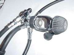 A diving regulator first stage with A-clamp connector and 90 degree swivel on one hose
 A first stage with DIN connector, 2 medium pressure hoses and 1 high pressure hose
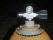
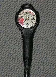 Submersible pressure gauge, or contents gauge
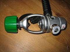 A button contents gauge on a first stage with A-clamp connector.
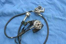 A 1960s era Sportsways "Waterlung" Regulator with integral reserve valve
The parts of a regulator are described as the major functional groups in downstream order as following the gas flow from the cylinder to its final use and accessories that are not part of the primary functional components but are commonly found on contemporary regulators. Some historically interesting models and components are described in a later section.
Single-hose two-stage open-circuit demand regulators
Most contemporary diving regulators are single-hose two-stage regulators. They consist of a first-stage regulator, and a second-stage demand valve. An intermediate-pressure hose connects these components to transfer air, and allows relative movement within the constraints of hose length and flexibility. Other intermediate-pressure hoses supply optional additional components.
First stage
The first stage of the regulator is mounted to the cylinder valve or manifold via one of the standard connectors (Yoke or DIN). It reduces cylinder pressure to an intermediate pressure, usually about 8 to 11 bars (120 to 160 psi) higher than the ambient pressure, also called interstage pressure, medium pressure or low pressure. The breathing gas is then supplied to the second stage through a hose.[3]:17-20
A balanced regulator first stage automatically keeps a constant pressure difference between the interstage pressure and the ambient pressure even as the tank pressure drops with consumption. The balanced regulator design allows the first stage orifice to be as large as needed without incurring performance degradation as a result of changing tank pressure.[3]:17-20
The first stage generally has several low-pressure outlets (ports) for second-stage regulators, BCD inflators and other equipment; and one or more high-pressure outlets, which allow a submersible pressure gauge (SPG) or gas-integrated diving computer to read the cylinder pressure. The valve may be designed so that one low-pressure port is designated "Reg" for the primary second stage regulator, because that port allows a higher flow rate to give less breathing effort at maximum demand. A small number of manufacturers have produced regulators with a larger than standard hose and port diameter for this primary outlet.[2]:50
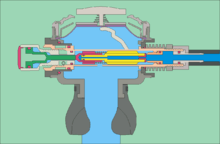
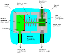 Diagram of the internal components of a balanced piston-type first stage
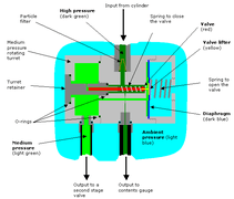 Diagram of the internal components of a diaphragm-type first stage
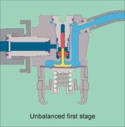 Diagram of the internal components of an unbalanced diaphragm first stage
 Diagram of the internal components of a balanced diaphragm first stage
 Animation of the internal components of a diaphragm-type first stage during the breathing cycle
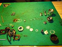 First stage disassembled
The mechanism inside the first stage can be of the diaphragm type or the piston type. Both types can be balanced or unbalanced. Unbalanced regulators have the cylinder pressure pushing the first stage upstream valve closed, which is opposed by the intermediate stage pressure and a spring. As cylinder pressure falls the closing force is less, so the regulated pressure increases at lower tank pressure. To keep this pressure rise within acceptable limits the high-pressure orifice size is limited, but this decreases the total flow capacity of the regulator. A balanced regulator keeps about the same ease of breathing at all depths and pressures, by using the cylinder pressure to also indirectly oppose the opening of the first stage valve.[3]:17-20
Piston-type first stage
Some components of piston-type first stages are easier to manufacture and have a simpler design than the diaphragm type. They may need more careful maintenance because some internal moving parts may be exposed to water and any contaminants in the water.[3]:9-13
The piston in the first stage is rigid and acts directly on the seat of the valve. The pressure in the intermediate pressure chamber drops when the diver inhales from the second stage valve, this causes the piston to lift off the stationary valve seat as the piston slides into the intermediate pressure chamber. The now open valve permits high pressure gas to flow into the medium pressure chamber until the pressure in the chamber has risen enough to push the piston back into its original position against the seat and thus close the valve.[3]:9-13
Diaphragm-type first stage
Diaphragm-type first stages are more complex and have more components than the piston type. Their design makes them particularly suited to cold water diving and to working in saltwater and water containing a high degree of suspended particles, silt, or other contaminating materials, since the only parts exposed to the water are the valve opening spring and the diaphragm, all other parts are sealed off from the environment. In some cases the diaphragm and spring are also sealed from the environment.[22][3]:9-13
The diaphragm is a flexible cover to the medium (intermediate) pressure chamber. When the diver consumes gas from the second stage, the pressure falls in the medium pressure chamber and the diaphragm deforms inwards pushing against the valve lifter. This opens the high pressure valve permitting gas to flow past the valve seat into the medium-pressure chamber. When the diver stops inhaling, pressure in the medium pressure chambers rises and the diaphragm returns to its neutral flat position and no longer presses on the valve lifter shutting off the flow until the next breath is taken.[3]:9-13
Balancing
If a regulator stage has an architecture that compensates for a change of upstream pressure on the moving parts of the valve so that a change in supply pressure does not affect the force required to open the valve, the stage is described as balanced. Upstream and downstream valves, first and second stages, and diaphragm and piston operation can be balanced or unbalanced, and a full description of a stage will specify which of all of these options apply. For example a regulator may have a balanced piston first stage with a balanced downstream second stage. Both balanced and unbalanced piston first stages are fairly common, but most diaphragm first stages are balanced. Balancing the first stage has a greater overall affect on the performance of a regulator, as the variation in supply pressure from the cylinder is much greater than the variation in interstage pressure, even with an unbalanced first stage. However the second stage operates on very a small pressure differential and is more sensitive to variations in supply pressure. Most top range regulators have at least one balanced stage, but it is not clear that balancing both stages makes a noticeable difference to performance.[3]:17–20
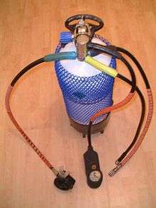
Connection of first-stage regulator to the cylinder valve or cylinder manifold
.jpg)
In an open circuit scuba set, the first-stage of the regulator has an A-clamp, also known as a yoke or international connection, or a DIN fitting to connect it to the pillar valve of the diving cylinder. There are also European standards for scuba regulator connectors for gases other than air.
Yoke valves (sometimes called A-clamps from their shape) are the most popular regulator connection in North America and several other countries. They clamp the high pressure inlet opening of the regulator against the outlet opening of the cylinder valve, and are sealed by an O-ring in a groove in the contact face of the cylinder valve. The user screws the clamp in place finger-tight to hold the metal surfaces of cylinder valve and regulator first stage in contact, compressing the o-ring between the radial faces of valve and regulator. When the valve is opened, gas pressure presses the O-ring against the outer cylindrical surface of the groove, completing the seal. The diver must take care not to screw the yoke down too tightly, or it may prove impossible to remove without tools. Conversely, failing to tighten sufficiently can lead to O-ring extrusion under pressure and a major loss of breathing gas. This can be a serious problem if it happens when the diver is at depth. Yoke fittings are rated up to a maximum of 240 bar working pressure.
The DIN fitting is a type of direct screw-in connection to the cylinder. The DIN system is less common worldwide, but has the advantage of withstanding greater pressure, up to 300 bar, allowing use of high-pressure steel cylinders. They are less susceptible to blowing the O-ring seal if banged against something while in use. DIN fittings are the standard in much of Europe and are available in most countries. The DIN fitting is considered more secure and therefore safer by many technical divers.[4]:117
Adapters are available enabling a DIN first-stage to be attached to a cylinder with a yoke fitting valve, and for a yoke first stage to be attached to a DIN cylinder valve.[4]:118
Most cylinder valves are currently of the K-valve type, which is a simple manually operated screw-down on-off valve. In the mid-1960s, J-valves were widespread. J-valves contain a spring-operated valve that is restricts or shuts off flow when tank pressure falls to 300-500 psi, causing breathing resistance and warning the diver that he or she is dangerously low on air. The reserve air is released by pulling a reserve lever on the valve. J-valves fell out of favor with the introduction of pressure gauges, which allow divers to keep track of their air underwater, especially as the valve-type is vulnerable to accidental release of reserve air and increases the cost and servicing of the valve. J-valves are occasionally still used when work is done in visibility so poor that the pressure gauge cannot be seen, even with a light.[4]:167–178[23]:Sec 7.2.2
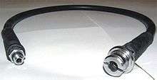
Interstage hose
A medium (intermediate) pressure hose is used to carry breathing gas (typically at between 8 and 10 bar above ambient) from the first stage regulator to the second stage, or demand valve, which is held in the mouth by the diver, or attached to the full face mask or diving helmet.[4]:88 The standard interstage hose is 30 inches (76 cm) long, but 40 inches (100 cm) hoses are standard for Octopus regulators and 7 feet (2.1 m) hoses are popular for technical diving, particularly for cave and wreck penetration where space constraints may make it necessary to swim in single file while sharing gas. Other lengths are also available. Most low pressure ports are threaded 3/8"UNF, but a few regulators were marketed with one 1/2"UNF port intended for the primary demand valve. High pressure ports are almost exclusively 7/16"UNF. There is no possibility of connecting a hose to the wrong pressure port.[4]:112
Second-stage or Demand valve
Upstream valves
In an upstream valve, the moving part works against the pressure and opens in the opposite direction to the flow of gas. They are often made as tilt-valves, which are mechanically extremely simple and reliable, but are not amenable to fine tuning.[4]:14
If the first stage leaks and the inter-stage over-pressurizes, the second stage downstream valve opens automatically resulting in a "freeflow". With an upstream valve, the result of over-pressurization may be a blocked valve. This will stop the supply of breathing gas and possibly result in a ruptured hose or the failure of another second stage valve, such as one that inflates a buoyancy device. When a second stage upstream tilt valve is used a relief valve should be included by the manufacturer on the first stage regulator to protect the intermediate hose.[4]:9
If a shut-off valve is fitted between the first and second stages, as is found on scuba bailout systems used for commercial diving and in some technical diving configurations, the demand valve will normally be isolated and unable to function as a relief valve. In this case an overpressure valve must be fitted to the first stage if it does not already have one. As very few contemporary (2016) scuba regulator first stages are factory fitted with overpressure relief valves, they are available as aftermarket accessories which can be screwed into any low pressure port available on the first stage.[24]
Downstream valves
Most modern demand valves use a downstream rather than an upstream valve mechanism. In a downstream valve, the moving part of the valve opens in the same direction as the flow of gas and is kept closed by a spring. The usual form of downstream valve is a spring-loaded poppet with a hard elastomer seat sealing against an adjustable metal "crown" around the inlet orifice. The poppet is lifted away from the crown by a lever operated by the diaphragm.[4]:13–15 Two patterns are commonly used. One is the classic push-pull arrangement, where the actuating lever goes onto the end of the valve shaft and is held on by a nut. Any deflection of the lever is converted to an axial pull on the valve shaft, lifting the seat off the crown and allowing air to flow.[4]:13 The other is the barrel poppet arrangement, where the poppet is enclosed in a tube which crosses the regulator body and the lever operates through slots in the sides of the tube. The far end of the tube is accessible from the side of the casing and a spring tension adjustment screw may be fitted for limited diver control of the cracking pressure. This arrangement also allows relatively simple pressure balancing of the second stage.[4]:14,18
A downstream valve will function as an over-pressure valve when the inter-stage pressure is raised sufficiently to overcome the spring pre-load. If the first stage leaks and the inter-stage over-pressurizes, the second stage downstream valve opens automatically. if the leak is bad this could result in a "freeflow", but a slow leak will generally cause intermittent "popping" of the DV, as the pressure is released and slowly builds up again.[4]:
Servo-controlled valves
Some demand valves use a small, sensitive pilot valve to control the opening of the main valve. The Poseidon Jetstream and Xstream and Oceanic Omega second stages are examples of this technology. They can produce very high flow rates for a small pressure differential, and particularly for a relatively small cracking pressure. They are generally more complicated and expensive to service.[4]:16
Exhaust valves
Exhaust valves are necessary to prevent the diver inhaling water, and to allow a negative pressure difference to be induced over the diaphragm to control the demand valve. The exhaust valves should operate at a very small pressure difference, and cause as little resistance to flow as reasonably possible, without being cumbersome and bulky. Elastomer mushroom valves serve the purpose adequately,[4]:108 though duckbill valves were also common in twin-hose regulators. Where it is important to avoid leaks back into the regulator, such as when diving in contaminated water, a system of two sets of valves in series can reduce the risk of contamination. A more complex option which can be used for surface supplied helmets, is to use a reclaim exhaust system which uses a separate flow regulator to control the exhaust which is returned to the surface in a dedicated hose in the umbilical.[5]:109
Exhaust manifold
The exhaust manifold (exhaust tee, exhaust cover, whiskers) is the ducting that protects the exhaust valve(s) and diverts the exhaled air to the sides so that it does not bubble up in the diver's face and obscure the view. This is not necessary for twin hose regulators as they exhaust air behind the shoulders.[4]:33
Purge button
A standard fitting on single-hose second stages, both mouth-held and built into a full-face mask or demand helmet, is the purge-button, which allows the diver to manually deflect the diaphragm to open the valve and cause air to flow into the casing. This is usually used to purge the casing or full-face mask of water if it has flooded. This will often happen if the second stage is dropped or removed from the mouth while under-water.[4]:108 It is either a separate part mounted in the front cover or the cover may be made flexible and serves as the purge button. Depressing the purge button presses against the diapragm directly over the lever of the demand valve, and this movement of the lever opens the valve to release air through the regulator.[25] The tongue may be used to block the mouthpiece during purging to prevent water or other matter in the regulator from being blown into the diver's airway by the air blast. This is particularly important when purging after vomiting through the regulator.
The purge button is also used by recreational divers to inflate a delayed surface marker buoy or lifting bag. Any time that the purge button is operated, the diver must be aware of the potential for a freeflow and be ready to deal with it.[26]
User adjustable flow modifiers
It may be desirable for the diver to have some control over the flow characteristics of the demand valve. The usual adjustable aspects are cracking pressure and the feedback from flow rate to internal pressure of the second stage housing. The inter-stage pressure of surface supplied demand breathing apparatus is controlled manually at the control panel, and does not automatically adjust to the ambient pressure in the way that most scuba first stages do, as this feature is controlled by feedback to the first stage from ambient pressure. This has the effect that the cracking pressure of a surface supplied demand valve will vary slightly with depth, so some manufacturers provide a manual adjustment knob on the side of the demand valve housing to adjust spring pressure on the downstream valve, which controls the cracking pressure. The knob is known to commercial divers as "dial-a-breath". A similar adjustment is provided on some high-end scuba demand valves, to allow the user to manually tune the breathing effort at depth[4]:17
Scuba demand valves which are set to breathe lightly (low cracking pressure, and low work of breathing) may tend to free-flow relatively easily, particularly if the gas flow in the housing has been designed to assist in holding the valve open by reducing the internal pressure. The cracking pressure of a sensitive demand valve is often less than the hydrostatic pressure difference between the inside of an air-filled housing and the water below the diaphragm when the mouthpiece is pointed upwards. To avoid excessive loss of gas due to inadvertent activation of the valve when the DV is out of the diver's mouth, some second stages have a desensitising mechanism which causes some back-pressure in the housing, by impeding the flow or directing it against the inside of the diaphragm.[4]:21
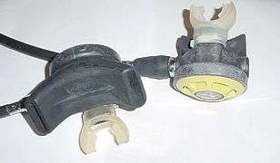 Primary and secondary (yellow) demand valves.
 Animation of demand valve function during the breathing cycle
 Air flow through the exhaust valve
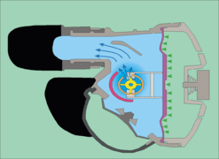 Inhalation flow with venturi assist activated
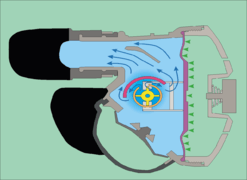 Inhalation flow with venturi assist de-activated
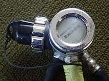
Twin-hose open-circuit demand scuba regulators
The "twin", "double" or "two" hose configuration of scuba demand valve was the first in general use.[27] This type of regulator has two large bore corrugated breathing tubes. One tube is to supply air from the regulator to the mouthpiece, and the second tube delivers the exhaled gas to a point where the ambient pressure is identical to the demand diaphragm, where it is released through a rubber duck-bill one-way valve, and comes out of the holes in the cover. Advantages of this type of regulator are that the bubbles leave the regulator behind the diver's head, increasing visibility, reducing noise and producing less load on the diver's mouth, They remain popular with some underwater photographers and Aqualung brought out an updated version of the Mistral in 2005.[28][29]
In Cousteau's original aqualung prototype, there was no exhaust hose, and the exhaled air exited through a one-way valve at the mouthpiece. It worked out of water, but when he tested the aqualung in the river Marne air free-flowed from the regulator before it could be breathed when the mouthpiece was above the regulator. After that, he had the second breathing tube fitted. Even with both tubes fitted, raising the mouthpiece above the regulator increases the delivered pressure of gas and lowering the mouthpiece reduces delivered pressure and increases breathing resistance. As a result, many aqualung divers, when they were snorkeling on the surface to save air while reaching the dive site, put the loop of hoses under an arm to avoid the mouthpiece floating up causing free flow.
Ideally the delivered pressure is equal to the resting pressure in the diver's lungs as this is what human lungs are adapted to breathe. With a twin hose regulator behind the diver at shoulder level, the delivered pressure changes with diver orientation. if the diver rolls on his or her back the released air pressure is higher than in the lungs. Divers learned to restrict flow by using their tongue to close the mouthpiece. When the cylinder pressure was running low and air demand effort rising, a roll to the right side made breathing easier. The mouthpiece can be purged by lifting it above the regulator(shallower), which will cause a free flow.[30]:341
Twin hose regulators have been superseded almost completely by single hose regulators and became obsolete for most diving since the 1980s.[31]
The original twin-hose regulators usually had no ports for accessories, though some has a high pressure port for a submersible pressure gauge. Some later models have one or more low-pressure ports between the stages, which can be used to supply direct feeds for suit or BC inflation and/or a secondary single hose demand valve, and a high pressure port for a submersible pressure gauge.[30] The new Mistral is an exception as it is based on the Aqualung Titan first stage. which has the usual set of ports.[28]
The twin-hose arrangement with a mouthpiece or full-face mask is common in rebreathers, but as part of the breathing loop, not as part of a regulator. The associated demand valve comprising the bail-out valve is a single hose regulator.
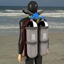 Twin-hose twin cylinder aqualung configuration
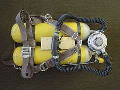 Twin 7l cylinders with Draeger harness, valves, manifold and regulator from c. 1965
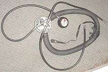 Nemrod twin-hose regulator made in the 1980s. It has one low-pressure port, which feeds the left (inhalation) hose. Its mouthpiece can be strapped in.
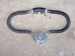 A Dräger two-stage twin-hose regulator
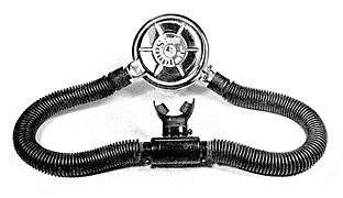 Beuchat "Souplair" single stage twin hose regulator
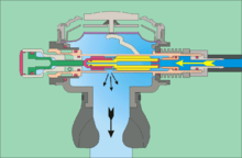
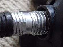
The mechanism of the twin hose regulator is packaged in a usually circular metal housing mounted on the cylinder valve behind the diver's neck. The demand valve component of a two-stage twin hose regulator is thus mounted in the same housing as the first stage regulator, and in order to prevent free-flow, the exhaust valve must be located at the same depth as the diaphragm, and the only reliable place to do this is in the same housing. The air flows through a pair of corrugated rubber hoses to and from the mouthpiece. The supply hose is connected to one side of the regulator body and supplies air to the mouthpiece through a non-return valve, and the exhaled air is returned to the regulator housing on the outside of the diaphragm, also through a non-return valve on the other side of the mouthpiece and usually through another non-return exhaust valve in the regulator housing - often a "duckbill" type.[30]
A non-return valve is usually fitted to the breathing hoses where they connect to the mouthpiece. This prevents any water that gets into the mouthpiece from going into the inhalation hose, and ensures that once it is blown into the exhalation hose that it cannot flow back. This slightly increases the flow resistance of air, but makes the regulator easier to clear.[30]:341
Some early twin hose regulators were of single-stage design. The first stage functions in a way similar to the second stage of two-stage demand valves, but would be connected directly to the cylinder valve and reduced high pressure air from the cylinder directly to ambient pressure on demand. This could be done by using a longer lever and larger diameter diaphragm to control the valve movement, but there was a tendency for cracking pressure, and thus work of breathing, to vary as the cylinder pressure dropped.[30]
Twin-hose without visible regulator valve (fictional)
This type is mentioned here because it is very familiar in comics and other drawings, as a wrongly-drawn twin-hose two-cylinder aqualung, with one wide hose coming out of each cylinder top to the mouthpiece with no apparent regulator valve, much more often than a correctly-drawn twin-hose regulator (and often of such breathing sets being used by combat frogmen): see Frogman#Errors about frogmen found in public media. It would not work in the real world.[32]
Performance
In Europe, EN 250: 2014 – Respiratory Equipment – Open Circuit Self - Contained Compressed Air Diving Apparatus – Requirements, Testing and Marking defines the minimum requirements for breathing performance of regulators,[33] and BS 8547:2016 defines requirements for demand regulators to be used at depths exceeding 50 m.[34] EN 13949: 2003 – Respiratory Equipment – Open Circuit Self-Contained Diving Apparatus for use with Compressed Nitrox and Oxygen – Requirements, Testing, Marking defines requirements for regulators to be used with raised levels of oxygen.[33]
EN 15333 – 1: 2008 COR 2009 – Respiratory Equipment – Open-Circuit Umbilical Supplied Compressed Gas Diving Apparatus – Part 1: Demand Apparatus. and EN 15333 – 2: 2009 – Respiratory Equipment – Open-Circuit Umbilical Supplied Compressed Gas Diving Apparatus – Part 2: Free Flow Apparatus are the relevant standards for surface supplied equipment.[33]
EN 14143: 2013 – Respiratory Equipment – Self-Contained Re-Breathing Diving Apparatus defines minimum requirements for rebreathers.[33]
The original Cousteau twin-hose diving regulators could deliver about 140 litres of air per minute at continuous flow and that was officially thought to be adequate, but divers sometimes needed a higher instantaneous rate and had to learn not to "beat the lung", i.e. to breathe faster than the regulator could supply. Between 1948 and 1952 Ted Eldred designed his Porpoise single hose regulator to supply up to 300 liters per minute.[35]
In the United States Military, scuba regulators must comply with performance specifications set out in Mil-R-24169B.[36][37][38][39]
Various breathing machines have been developed and used for assessment of breathing apparatus performance.[40] ANSTI Test Systems Ltd (UK) has developed a testing machine that measures the inhalation and exhalation effort in using a regulator. Publishing results of the performance of regulators in the ANSTI test machine has resulted in big performance improvements.[41]
Malfunctions and failure modes
Most regulator malfunctions involve improper supply of breathing gas or water leaking into the gas supply. There are two failure modes, where the regulator shuts off delivery, which is extremely rare, and free-flow, where the delivery will not stop and can quickly exhaust a scuba supply.[2]
- Inlet filter blockage
- The inlet to the cylinder valve may be protected by a sintered filter, and the inlet to the first stage is usually protected by a filter, both to prevent corrosion products or other contaminants in the cylinder from getting into the fine toleranced gaps in the moving parts of the first and second stage and jamming them, either open or closed. If enough dirt gets into these filters they themselves can be blocked sufficiently to reduce performance, but are unlikely to result in a total or sudden catastrophic failure.[42]
- Free-flow
- Either of the stages may get stuck in the open position, causing a continuous flow of gas from the regulator known as a free-flow. This can be triggered by a range of causes, some of which can be easily remedied, others not. Possible causes include incorrect interstage pressure setting, incorrect second stage valve spring tension, damaged or sticking valve poppet, damaged valve seat, valve freezing, wrong sensitivity setting at the surface and in Poseidon servo-assisted second stages, low interstage pressure.[42]
- Sticking valves
- The moving parts in first and second stages have fine tolerances in places, and some designs are more susceptible to contaminants causing friction between the moving parts. this may increase cracking pressure, reduce flow rate, increase work of breathing or induce free-flow, depending on what part is affected.
- Freezing
- In cold conditions the cooling effect of gas expanding through a valve orifice may cool either first or second stage sufficiently to cause ice to form. External icing may lock up the spring and exposed moving parts of first or second stage, and freezing of moisture in the air may cause icing on internal surfaces. Either may cause the moving parts of the affected stage to jam open or closed. If the valve freezes closed, it will usually defrost quite rapidly and start working again, and may freeze open soon after. Freezing open is more of a problem, as the valve will then free-flow and cool further in a positive feedback loop, which can normally only be stopped by closing the cylinder valve and waiting for the ice to thaw. If not stopped, the cylinder will rapidly be emptied.[43]
- Intermediate pressure creep
- This is a slow leak of the first stage valve. The effect is for the interstage pressure to rise until either the next breath is drawn, or the pressure exerts more force on the second stage valve than can be resisted by the spring, and the valve opens briefly, often with a popping sound, to relieve the pressure. the frequency of the popping pressure relief depends on the flow in the second stage, the back pressure, the second stage spring tension and the magnitude of the leak. It may range from occasional loud pops to a constant hiss. Underwater the second stage may be damped by the water and the loud pops may become an intermittent or constant stream of bubbles. This is not usually a catastrophic failure mode, but should be fixed as it will get worse, and it wastes gas.[42]
- Gas leaks
- Air leaks can be caused by burst or leaky hoses, defective o-rings, blown o-rings, particularly in yoke connectors, loose connections, and several of the previously listed malfunctions. Low pressure inflation hoses may fail to connect properly, or the non-return valve may leak. A burst low pressure hose will usually lose gas faster than a burst high pressure hose, as HP hoses usually have a flow restriction orifice in the fitting that screws into the port,[4]:185 as the submersible pressure gauge does not need high flow, and a slower pressure increase in the gauge hose is less likely to overload the gauge, while the hose to a second stage must provide high peak flow rate to minimize work of breathing.[42] A relatively common o-ring failure occurs when the yoke clamp seal extrudes due to insufficient clamp force or elastic deformation of the clamp by impact with the environment.
- Wet breathing
- Wet breathing is caused by water getting into the regulator and compromising breathing comfort and safety. Water can leak into the second stage body through damaged soft parts like torn mouthpieces, damaged exhaust valves and perforated diaphragms, through cracked housings, or through poorly sealing or fouled exhaust valves.[42]
- Excessive work of breathing
- High work of breathing can be caused by high inhalation resistance, high exhalation resistance or both. High inhalation resistance can be caused by high cracking pressure, low interstage pressure, friction in second stage valve moving parts, excessive spring loading, or sub-optimum valve design. It can usually can be improved by servicing and tuning, but some regulators cannot deliver high flow at great depths without high work of breathing. High exhalation resistance is usually due to a problem with the exhaust valves, which can stick, stiffen due to deterioration of the materials, or may have an insufficient flow passage area for the service.[42]
- Juddering, shuddering and moaning
- This is caused by an irregular and unstable flow from the second stage, It may be caused by a slight positive feedback between flow rate in the second stage body and diaphragm deflection opening the valve, which is not sufficient to cause free-flow, but enough to cause the system to hunt. It is more common on high-performance regulators which are tuned for maximum flow and minimum work of breathing, particularly out of the water, and often reduces or resolves when the regulator is immersed and the ambient water damps the movement of the diaphragm and other moving parts. Desensitising the second stage by closing venturi assists or increasing the valve spring pressure often stops this problem. Juddering may also be caused by excessive but irregular friction of valve moving parts.[42]
- Physical damage to the housing or components
- Damage such as cracked housings, torn or dislodged mouthpieces, damaged exhaust fairings, can cause gas flow problems or leaks, or can make the regulator uncomfortable to use or difficult to breathe from.
Accessories and special features
Anti-freezing modification
As gas leaves the cylinder it decreases in pressure in the first stage, becoming very cold due to adiabatic expansion. Where the ambient water temperature is less than 5 °C any water in contact with the regulator may freeze. If this ice jams the diaphragm or piston spring, preventing the valve closing, a free-flow may ensue that can empty a full cylinder within a minute or two, and the free-flow causes further cooling in a positive feedback loop.[43] Generally the water that freezes is in the ambient pressure chamber around a spring that keeps the valve open and not moisture in the breathing gas from the cylinder, but that is also possible if the air is not adequately filtered. The modern trend of using plastics to replace metal components in regulators encourages freezing because it insulates the inside of a cold regulator from the warmer surrounding water. Some regulators are provided with heat exchange fins in areas where cooling due to air expansion is a problem, such as around the second stage valve seat on some regulators.[44]
Cold water kits can be used to reduce the risk of freezing inside the regulator. Some regulators come with this as standard, and some others can be retrofitted. Environmental sealing of the diaphragm main spring chamber using a soft secondary diaphragm and hydrostatic transmitter[4]:195 or a silicone, alcohol or glycol/water mixture antifreeze liquid in the sealed spring compartment can be used for a diaphragm regulator.[4] Silicone grease in the spring chamber can be used on a piston first stage.[4] The Poseidon Xstream first stage insulates the external spring and spring housing from the rest of the regulator, so that it is less chilled by the expanding air, and provides large slots in the housing so that the spring can be warmed by the water, thus avoiding the problem of freezing up the external spring.[45]
Pressure relief valve
A downstream demand valve serves as a fail safe for over-pressurization: if a first stage with a demand valve malfunctions and jams in the open position, the demand valve will be over-pressurized and will "free flow". Although it presents the diver with an imminent "out of air" crisis, this failure mode lets gas escape directly into the water without inflating buoyancy devices. The effect of unintentional inflation might be to carry the diver quickly to the surface causing the various injuries that can result from an over-fast ascent. There are circumstances where regulators are connected to inflatable equipment such as a rebreather's breathing bag, a buoyancy compensator, or a drysuit, but without the need for demand valves. Examples of this are argon suit inflation sets and "off board" or secondary diluent cylinders for closed-circuit rebreathers. When no demand valve is connected to a regulator, it should be equipped with a pressure relief valve, unless it has a built in over pressure valve, so that over-pressurization does not inflate any buoyancy devices connected to the regulator.
Pressure monitoring
A diving regulator has one or two 7/16"UNF high pressure ports upstream of all pressure-reducing valves to monitor the gas pressure remaining in the diving cylinder, provided that the valve is open.[1] There are several types of contents gauge.
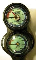
Standard submersible pressure gauge
The standard arrangement has a high pressure hose leading to a submersible pressure gauge (SPG) (also called a contents gauge).[4] This is an analog mechanical gauge that is connected to the first stage by a high pressure hose. It displays with a pointer moving over a dial,[1] usually about 50 millimetres (2.0 in) diameter. Sometimes they are mounted in a console, which is a plastic or rubber case that holds the air pressure gauge and other instruments such as a depth gauge, dive computer and/or compass.
Button gauges

These are coin-sized analog pressure gauges directly mounted to a high-pressure port on the first stage. They are compact, have no dangling hoses, and few points of failure. They are generally not used on back mounted cylinders because the diver cannot see them there when underwater. They are sometimes used on side slung stage cylinders. Due to their small size, it can be difficult to read the gauge to a resolution of less than 20 bars (300 psi).
Air integrated computers
Some dive computers are designed to measure, display, and monitor pressure in the diving cylinder. This can be very beneficial to the diver, but if the dive computer fails the diver can no longer monitor his or her gas reserves. Most divers using a gas-integrated computer will also have a standard air pressure gauge. The computer is either connected to the first stage by a high pressure hose, or has two parts - the pressure transducer on the first stage and the display at the wrist or console, which communicate by wireless data transmission link; the signals are encoded to eliminate the risk of one diver's computer picking up a signal from another diver's transducer or radio interference from other sources.[46]
Secondary demand valve (Octopus)
As a nearly universal standard practice in modern recreational diving, the typical single-hose regulator has a spare demand valve fitted for emergency use by the diver's buddy, typically referred to as the octopus because of the extra hose, or secondary demand valve. The octopus was invented by Dave Woodward[47] at UNEXSO around 1965-6 to support the free dive attempts of Jacques Mayol. Woodward believed that having the safety divers carry two second stages would be a safer and more practical approach than buddy breathing in the event of an emergency.[47] The medium pressure hose on the octopus is usually longer than the medium pressure hose on the primary demand valve that the diver uses, and the demand valve and/or hose may be colored yellow to aid in locating in an emergency. The secondary regulator should be clipped to the diver's harness in a position where it can be easily seen and reached by both the diver and the potential sharer of air. The longer hose is used for convenience when sharing air, so that the divers are not forced to stay in an awkward position relative to each other. Technical divers frequently extend this feature and use a 5-foot or 7-foot hose, which allows divers to swim in single file while sharing air, which may be necessary in restricted spaces inside wrecks or caves.
The secondary demand valve can be a hybrid of a demand valve and a buoyancy compensator inflation valve. Both types are sometimes called alternate air sources. When the secondary demand valve is integrated with the buoyancy compensator inflation valve, since the inflation valve hose is short (usually just long enough to reach mid-chest), in the event of a diver running out of air, the diver with air remaining would give his or her primary second stage to the out-of-air diver, and switch to their own inflation valve.
A demand valve on a regulator connected to a separate independent diving cylinder would also be called an alternate air source and also a redundant air source, as it is totally independent of the primary air source.
Mouthpiece
The mouthpiece is a part that the user grips in the mouth to make a watertight seal. It is a short flattened-oval tube that goes in between the lips, with a curved flange that fits between the lips and the teeth and gums. On the inner ends of the flange there are two tabs with enlarged ends, which are gripped between the teeth. Most recreational diving regulators are fitted with a mouthpiece. In twin-hose regulators and rebreathers, "mouthpiece" may refer to the whole assembly between the two flexible tubes. A mouthpiece prevents clear speech, so a full-face mask is preferred where voice communication is needed.
In a few models of scuba regulator the mouthpiece also has an outer rubber flange that fits outside the lips and extends into two straps that fasten together behind the neck.[30]:184 This helps to keep the mouthpiece in place if the user's jaws go slack through unconsciousness or distraction. The mouthpiece safety flange may also be a separate component.[30]:154 The attached neck strap also allows the diver to keep the regulator hanging under the chin where it is protected and ready for use. Recent mouthpieces do not usually include an external flange, but the practice of using a neck strap has been revived by technical divers who use a bungee or surgical rubber "necklace" which can come off the mouthpiece without damage if pulled firmly.[48]
The original mouthpieces were usually made from natural rubber and could cause an allergic reaction in some divers. This has been overcome by the use of hypo-allergenic synthetic elastomers such as silicone rubbers.[49]
Full-face mask or helmet
This is stretching the concept of accessory a bit, as it would be equally valid to call the regulator an accessory of the full face mask or helmet, but the two items are closely connected and generally found in use together.
Most full face masks and probably most diving helmets currently in use are open circuit demand systems, using a demand valve (in some cases more than one) and supplied from a scuba regulator or a surface supply umbilical from a surface supply panel using a surface supply regulator to control the pressure of primary and reserve air or other breathing gas.
Lightweight demand diving helmets are almost always surface supplied, but full face masks are used equally appropriately with scuba open circuit, scuba closed circuit (rebreathers), and surface supplied open circuit.
The demand valve is usually firmly attached to the helmet or mask, but there are a few models of full face mask that have removable demand valves with quick connections allowing them to be exchanged under water. These include the Dräger Panorama and Kirby-Morgan 48 Supermask.
Buoyancy compensator and dry suit inflation hoses
Hoses may be fitted to low pressure ports of the regulator first stage to provide gas for inflating buoyancy compensators and/or dry suits. These hoses usually have a quick-connector end with an automatically sealing valve which blocks flow if the hose is disconnected from the buoyancy compensator or suit.[2]:50 There are two basic styles of connector, which are not compatible with each other. The high flow rate CEJN 221 fitting has a larger bore and allows gas flow at a fast enough rate for use as a connector to a demand valve. This is sometimes seen in a combination BC inflator/deflator mechanism with integrated secondary DV (octopus), such as in the AIR II unit from Scubapro. The low flow rate Seatec connector is more common and is the industry standard for BC inflator connectors, and is also popular on dry suits, as the limited flow rate reduces the risk of a blow-up if the valve sticks open. The high flow rate connector is used by some manufacturers on dry suits.[50]
Various minor accessories are available to fit these hose connectors. These include interstage pressure gauges, which are used to troubleshoot and tune the regulator (not for use underwater), noisemakers, used to attract attention underwater and on the surface, and valves for inflating tires and inflatable boat floats, making the air in a scuba cylinder available for other purposes.
Instrument consoles
Also called combo consoles, these are usually hard rubber or tough plastic moldings which enclose the submersible pressure gauge and have mounting sockets for other diver instrumentation, such as decompression computers, underwater compass, timer and/or depth gauge and occasionally a small plastic slate on which notes can be written either before or during the dive. These instruments would otherwise be carried somewhere else such as strapped to the wrist or forearm or in a pocket and are only regulator accessories for convenience of transport and access, and at greater risk of damage during handling.
Automatic closure device
The auto-closure device (ACD) is a mechanism for closing off the inlet opening of a regulator first stage when it is disconnected from a cylinder. A spring-loaded plunger in the inlet is mechanically depressed by contact with the cylinder valve when the regulator is fitted to the cylinder, which opens the port through which air flows into the regulator. In the normally closed condition when not mounted, this valve prevents ingress of water and other contaminants to the first stage interior which could be caused by negligent handling of the equipment or by accident. This is claimed by the manufacturer to extend the service life of the regulator and reduce risk of failure due to internal contamination.[51] However, it is possible for an incorrectly installed ACD to shut off gas supply from a cylinder still containing gas during a dive.[52][53]
Gas compatibility
Recreational scuba nitrox service
Standard air regulators are considered to be suitable for nitrox mixtures containing 40% or less oxygen by volume, both by NOAA, which conducted extensive testing to verify this, and by most recreational diving agencies.[4]:25
Surface supplied nitrox service
When surface supplied equipment is used the diver does not have the option of simply taking out the DV and switching to an independent system, and gas switching may be done during a dive, including use of pure oxygen for accelerated decompression. To reduce the risk of confusion or getting the system contaminated, surface supplied systems may be required to be oxygen clean for all services except straight air diving.
Oxygen service
Regulators to be used with pure oxygen and nitrox mixtures containing more than 40% oxygen by volume should use oxygen compatible components and lubricants, and be cleaned for oxygen service.[54]
Helium service
Helium is an exceptionally nonreactive gas and breathing gases containing helium do not require any special cleaning or lubricants. However, as helium is generally used for deep dives, it will normally be used with high performance regulators, suitable for the depth.
Exotic examples of historical interest
Ohgushi's Peerless Respirator
Invented in 1916 by Riichi Watanabi and the blacksmith Kinzo Ohgushi, and used with either surface supplied air or a 150 bar steel scuba cylinder holding 1000 litres free air, the valve supplied air to a mask over the diver's nose and eyes and the demand valve was operated by the diver's teeth. Gas flow was proportional to bite force and duration. The breathing apparatus was used successfully for fishing and salvage work and by the military Japanese Underwater Unit until the end of the Pacific War.[55][56]
First stage with integral reserve valve
A number of manufacturers produced integral reserve regulators in 1961 and 1962 with reasonable market acceptance. These regulators provided a lever operated mechanical reserve valve that restricted air flow when the pressure was below 500 psi. Alerted to having a low gas supply the diver would pull a rod to open the reserve valve and surface using the remaining gas. This feature provides reserve capacity on cylinders with plain valves. With this arrangement the reserve rod must also be transferred to the cylinder in use.[30]:166,167
Demone regulator
These unusual regulators were designed by Robert J. Dempster and made at his factory in Illinois, USA, from 1961 to 1965. The Demone Mark I and Demone Mark II are both two-stage regulators. The second-stage looks like the mouthpiece of a twin-hose regulator but has a small diaphragm on the front. The second-stage valve is inside the mouthpiece tube. The exhaled air goes into a corrugated coaxial exhaust hose which surrounds the intermediate-pressure hose and discharges about 60% of the way back to the first-stage to keep the bubbles away from the diver's face. Near the mouthpiece is a one-way valve to let outside water into the exhaust hose to avoid free flow if the diaphragm (at the mouth) is below the open end of the exhaust hose. The Mark I has hoses only on one side, and the Mark II has twinned intermediate-pressure hoses, each with its own coaxial exhaust hose and second stage, one assembly on each side of the diver's head, but with both second stages in the same mouthpiece housing and operated by the same diaphragm.[30]:93–100[57] This version has no large visible regulator.
Normalair breathing apparatus
This system is unusual in that it used a single stage single hose demand valve in a full-face mask. The high pressure supply hose routes over the shoulder, but from an inverted cylinder, which allows the user to easily reach the valve.[30]:249–253
Twin-hose with regulator on chest
In this unusual configuration the cylinder(s) are on the diver's back and are connected by an intermediate-pressure hose to a twin-hose regulator on the diver's chest.
- A design described in Practical Mechanics magazine in January 1955 as a home-made aqualung with a first-stage on the cylinder top leading through an intermediate-pressure hose to a large round second-stage (a converted Calor Gas regulator) on the diver's chest connected to the diver's mouthpiece by a twin-hose loop.[58]
- An early Australian design called a Lawson Lung was made in Sydney by a group of enthusiasts who were unable to get Aqua-lungs due to limited supply, based on the patented Costeau-Gagnan design, but modified to use available components. The regulators were made and tested at John Lawson’s jewellery factory in Greenwich, North Sydney. Only 12 were made, and had to be mounted on the chest to achieve acceptable performance.[59] [60][61]
Single stage pendulum open circuit scuba
For a few years in the mid-1950s, Draeger made the Draeger Delfin II (their first scuba regulator - it was marketed as the Barakuda (now IAC) in the USA): this was a single stage single hose "pendulum"" regulator with only one ambient pressure (corrugated) hose: the exhaled air went back down the hose to the cylinder mounted regulator and was released to outside through a one-way valve inside the casing. The end of the flexible tube was connected to the mouthpiece by a short quarter-circle of hard tube.[62][63] The two way hose would have caused dead space similar to a rebreather with a pendulum system.
Propulsive power from the stored energy
The concept of a diving regulator where the energy released as the air expands from cylinder pressure to the surrounding pressure as the diver inhales, is used to power a propeller has been patented, but no product ever appeared on the market.[64]
Full-face mask regulator

There have been some cases of a single-hose regulator final stage built into a full-face mask so that the mask's big front window, in conjunction with a flexible rubber seal joining it to its frame, functioned as a large and sensitive regulator diaphragm:
- Several versions of the Le Prieur breathing set. Yves Le Prieur first patented with Maurice Fernez, in 1926, a breathing apparatus using a mouthpiece, but as of 1933 he removed the mouthpiece and included a circular full-face mask in all following patents (like 1937, 1946 or 1947).[6]
- In 1934 René Commeinhes, from Alsace (France), adapted a Rouquayrol-Denayrouze apparatus for the use of firefighters. With new 1937 and 1942 patents (GC37 and GC42), his son Georges adapted this invention to underwater breathing by means of a single hose connected to a full-face mask.[18]
- Captain Trevor Hampton invented independently from Le Prieur a similar regulator-mask in the 1950s and submitted it for patent. The Royal Navy requisitioned the patent, but found no use for it and eventually released it. By then, the technology had advanced and it was too late to make this regulator-mask in bulk for sale.
Twin-hose, home-made
In 1956 and for some years afterwards in Britain, factory-made aqualungs were very expensive, and many aqualungs of this type were made by sport divers in diving clubs' workshops, using miscellaneous industrial and war-surplus parts. One necessary raw material was a Calor Gas bottled butane gas regulator, whose 1950s version was like an aqualung regulator's second stage but passed gas all the time because its diaphragm was spring-loaded; conversion included changing the spring and making several big holes in the wet-side casing. The cylinder was often an ex-RAF pilot's oxygen cylinder; some of these cylinders were called tadpoles from their shape.
In least one version of Russian twin-hose aqualung, the regulator did not have an A-clamp but screwed into a large socket on the cylinder manifold; that manifold was thin, and meandered somewhat. It had two cylinders and a pressure gauge. There is suspicion that those Russian aqualungs started as a factory-made improved descendant of an aqualung home-made by British sport divers and obtained unofficially by a Russian and taken to Russia.
Practical Mechanics design
This design was described in Practical Mechanics magazine in January 1955, as a home-made aqualung with a first-stage on the cylinder top leading through an intermediate-pressure hose to a large round second-stage (a converted Calor Gas regulator) on the diver's chest connected to the diver's mouthpiece by a twin-hose loop.[65]
Manufacturers and their brands
- Air Liquide: La Spirotechnique, Apeks and Aqua Lung
- American Underwater Products (ROMI Enterprises, of San Leandro, Calif.): Aeris,[66] Hollis Gear[67][68] and Oceanic
- Atomic Aquatics
- Beuchat
- Cressi-Sub
- Deep6
- Dive Rite[69]
- Dräger
- Halcyon Diving System
- HTM Sports: Dacor and Mares
- Poseidon Diving Systems AB[70]
- ScubaPro
- Seac Sub
- Tusa[71]
- Tecline
- Zeagle[72]
References
- 1 2 3 NOAA Diving Program (U.S.) (28 Feb 2001). Joiner, James T, ed. NOAA Diving Manual, Diving for Science and Technology (4th ed.). Silver Spring, Maryland: National Oceanic and Atmospheric Administration, Office of Oceanic and Atmospheric Research, National Undersea Research Program. ISBN 978-0-941332-70-5. CD-ROM prepared and distributed by the National Technical Information Service (NTIS)in partnership with NOAA and Best Publishing Company
- 1 2 3 4 Barsky, Steven; Neuman, Tom (2003). Investigating Recreational and Commercial Diving Accidents. Santa Barbara, California: Hammerhead Press. ISBN 0-9674305-3-4.
- 1 2 3 4 5 6 7 8 9 10 Harlow, Vance (1999). "1 How a regulator works". Scuba regulator maintenance and repair. Warner, New Hampshire: Airspeed Press. pp. 1–26. ISBN 0-9678873-0-5.
- 1 2 3 4 5 6 7 8 9 10 11 12 13 14 15 16 17 18 19 20 21 22 23 24 25 26 27 28 Harlow, Vance (1999). Scuba regulator maintenance and repair. Warner, New Hampshire: Airspeed Press. ISBN 0-9678873-0-5.
- 1 2 3 4 Barsky, Steven (2007). Diving in High-Risk Environments (4th ed.). Ventura, California: Hammerhead Press. ISBN 978-0-9674305-7-7.
- 1 2 3 Républic Française. Ministère du Commerce et de l'Industrie. Direction de la Propriété Industrielle. Brevet d'Invention Gr. 6. - Cl. 3. No. 768.083
- ↑ Cresswell, Jeremy (2 June 2008). "Helium costs climb as diver demand soars". energyvoice.com. Retrieved 15 November 2016.
- 1 2 3 Crawford, J (2016). "Section 8.5 Bulk gas storage". Offshore Installation Practice (revised ed.). Oxford, UK: Butterworth-Heinemann. ISBN 9781483163192.
- ↑ Staff. "Ultrajewel 601 'Dirty Harry'". divingheritage.com. Diving Heritage. Retrieved 15 November 2016.
- ↑ Staff. "Closed Circuit Rebreather Mouthpieces-DSV/BOV(Dive/Surface Valve/Bail Out Valve)". www.divenet.com. Fullerton, California: Divematics,USA,Inc. Retrieved 16 November 2016.
- ↑ Académie des Sciences (16 September 1839). "Mécanique appliquée -- Rapport sur une cloche à plongeur inventée par M. Guillaumet (Applied mechanics—Report on a diving bell invented by Mr. Guillaumet)". Comptes rendus hebdomadaires des séances de l'Académie des Sciences (in French). Paris: Gauthier-Villars. 9: 363–366. Retrieved 26 September 2016.
- ↑ Perrier, Alain (2008). 250 Réponses aux questions du plongeur curieux (in French). Aix-en-Provence, France: Éditions du Gerfaut. p. 45. ISBN 9782351910337.
- ↑ Bevan, John (1990). "The First Demand Valve?" (PDF). SPUMS Journal. South Pacific Underwater Medicine Society. 20 (4): 239–240.
- ↑ "le scaphandre autonome". Archived from the original on 30 October 2012. Retrieved 17 November 2016.
Un brevet semblable est déposé en 1838 par William Newton en Angleterre. Il y a tout lieu de penser que Guillaumet, devant les longs délais de dépôt des brevets en France, a demandé à Newton de faire enregistrer son brevet en Angleterre où la procédure est plus rapide, tout en s'assurant les droits exclusifs d'exploitation sur le brevet déposé par Newton.
A similar patent was filed in 1838 by William Newton in England. There is every reason to think that owing to the long delays in filing patents in France, Guillaumet asked Newton to register his patent in England where the procedure was faster while ensuring the exclusive rights to exploit the patent filed by Newton. Note: The illustration of the apparatus in Newton's patent application is identical to that in Guillaumet's patent application; furthermore, Mr. Newton was apparently an employee of the British Office for Patents, who applied for patents on behalf of foreign applicants. Also from "le scaphandre autonome" Web site: Reconstruit au XXe siècle par les Américains, ce détendeur fonctionne parfaitement, mais, si sa réalisation fut sans doute effective au XIXe, les essais programmés par la Marine Nationale ne furent jamais réalisés et l'appareil jamais commercialisé. (Reconstructed in twentieth century by the Americans, this regulator worked perfectly; however, although it was undoubtedly effective in the nineteenth century, the test programs by the French Navy were never conducted and the apparatus was never sold.) - ↑ Dekker, David L. "1860. Benoit Rouquayrol – Auguste Denayrouze". Chronology of Diving in Holland. www.divinghelmet.nl. Retrieved 17 September 2016.
- ↑ Bahuet, Eric (19 October 2003). "Rouquayrol Denayrouze". Avec ou sans bulle ? (in French). plongeesout.com. Retrieved 16 November 2016.
- ↑ Commandant Le Prieur. Premier Plongée (First Diver). Editions France-Empire 1956
- 1 2 Tailliez, Philippe (January 1954). Plongées sans câble (in French). Paris: Editions Arthaud. p. 52.
- ↑ Musée du Scaphandre website (in French). Espalion, France https://web.archive.org/web/20121030022352/http://www.espalion-12.com/scaphandre/autonomie/scaphandre_autonome.htm. Archived from the original on 30 October 2012. Missing or empty
|title=(help) Mentions the contributions of several French inventors: Guillaumet, Rouquayrol and Denayrouze, Le Prieur, René and Georges Commheines, Gagnan and Cousteau - ↑ Bronnec, Jean Armand Louis; Gautier, Raymond Maurice (26 November 1956). Brevet d'Invention No. T126.597 B63b Appareil respiratoire notament pour plongeurs (in French). Paris: Ministere de l'Industrie et du Commerce – via Website of Luca Dibiza.
- 1 2 Lonsdale, Mark V. (2012). "Evolution of US Navy diving - Significant dates in Navy diving (1823 – 2001)". History of Navy Diving. Northwest Diving History Association. Retrieved 24 November 2016.
- ↑ Staff. "Environmental Dry Sealing System". First Stage Technology. Blackburn, United Kingdom: Apeks Marine Equipment. Retrieved 17 November 2016.
- ↑ Staff. "KM Over Pressure Relief Valve, Hi-Flow". Products. Santa Maria California: Diving Equipment Company of America (DECA). Retrieved 16 November 2016.
- ↑ Brittain, Colin (2004). "Protective clothing, scuba equipment and equipment maintenance". Let's Dive: Sub-Aqua Association Club Diver Manual (2nd ed.). Wigan, UK: Dive Print. p. 35. ISBN 0-9532904-3-3. Retrieved 6 January 2010.
- ↑ Brittain, Colin (2004). "Practical diver training". Let's Dive: Sub-Aqua Association Club Diver Manual (2nd ed.). Wigan, UK: Dive Print. p. 48. ISBN 0-9532904-3-3. Retrieved 6 January 2010.
- ↑ Vintage European Two Hose Regulator Collection
- 1 2 Staff (16 February 2005). "Aqua Lung Debuts the Comeback of the Double Hose Regulator". Sport Diver. Bonnier corporation. Retrieved 16 May 2017.
- ↑ Warren, Steve (November 2015). "The History Boys". Divernet - Gear features. www.divernet.com. Retrieved 16 May 2017.
- 1 2 3 4 5 6 7 8 9 10 Roberts, Fred M. (1963). Basic Scuba. Self-Contained Underwater Breathing Apparatus: Its Operation, Maintenance and Use (Enlarged Second ed.). New York: Van Nostrand Reinhold Co. ISBN 0 442 26824 6.
- ↑ Busuttili, Mike; Holbrook, Mike; Ridley, Gordon; Todd, Mike, eds. (1985). "The Aqualung". Sport diving – The British Sub-Aqua Club Diving Manual. London: Stanley Paul & Co Ltd. p. 36. ISBN 0-09-163831-3.
- ↑ Examples, and variations, at , ,
- 1 2 3 4 Staff (August 2014). "Diving Breathing Apparatus" (PDF). Diving Standards. Dublin: Health and Safety Authority. Archived from the original (PDF) on 18 November 2016. Retrieved 18 November 2016.
- ↑ Committee PH/4/7 (31 March 2016). BS 8547:2016 - Respiratory equipment. Breathing gas demand regulator used for diving to depths greater than 50 metres. Requirements and test methods. London: British Standards Institute. ISBN 978 0 580 89213 4.
- ↑ Ryan, Mark (23 December 2010). "Little known dive history – The world's first single hose regulator". ScubaGadget – Scuba News Service. scubagadget.com. Retrieved 16 May 2017.
- ↑ Middleton, JR (1980). "Evaluation of Commercially Available Open Circuit Scuba Regulators". United States Navy Experimental Diving Unit Technical Report. NEDU-2-80. Retrieved 2008-06-12.
- ↑ Morson, PD (1987). "Evaluation of Commercially Available Open Circuit Scuba Regulators". United States Navy Experimental Diving Unit Technical Report. NEDU-8-87. Retrieved 2008-06-12.
- ↑ Warkander, DE (2007). "Comprehensive Performance Limits for Divers' Underwater Breathing Gear: Consequences of Adopting Diver-Focused Limits". United States Navy Experimental Diving Unit Technical Report. NEDU-TR-07-02. Retrieved 12 June 2008.
- ↑ Staff (22 February 1982). "MIL-R-24169 › Regulator, Air Demand, Single Hose, Diver S". US Department of Defence. Retrieved 27 November 2016.
- ↑ Reimers, SD (1973). "Performance Characteristics and Basic Design Features of a Breathing Machine for Use to Depths of up to 3000 Feet of Sea Water". United States Navy Experimental Diving Unit. Panama City, Florida: NEDU. NEDU-20-73. Retrieved 12 June 2008.
- ↑ Staff (11 June 2006). "The ANSTI Machine: Evaluating A Regulator's Breathing Characteristics". Gear. Winter Park, Florida: Scuba Diving. A Bonnier Corporation Company. Retrieved 15 November 2016.
- 1 2 3 4 5 6 7 Harlow, Vance (1999). "10 Diagnosis". Scuba regulator maintenance and repair. Warner, New Hampshire: Airspeed Press. pp. 155–165. ISBN 0-9678873-0-5.
- 1 2 Clarke, John (2015). "Authorized for cold-water service: What Divers Should Know About Extreme Cold". ECO Magazine: 20–25. Retrieved 7 March 2015.
- ↑ Ward, Mike (9 April 2014). Scuba Regulator Freezing - Chilling Facts & Risks Associated with Cold Water Diving (PDF). DL-Regulator Freeze Research Study (Report). Panama City, Florida: Dive Lab Inc. Retrieved 16 May 2017.
- ↑ Staff. "Xstream user manual: English" (PDF). Art. no 4695 Issue 081001-1. Västra Frölunda, Sweden: Poseidon Diving Systems. Archived from the original (PDF) on 4 March 2016. Retrieved 17 November 2016.
- ↑ Staff. "Suunto Wireless Tank Pressure Transmitter". Accessories and spare parts. Suunto. Retrieved 27 November 2016.
- 1 2 http://www.internationallegendsofdiving.com/FeaturedLegends/woodward_bio.htm
- ↑ Davis, Andy (2011). "How to Tie a Regulator Bungee Necklace". Scuba Tech Philippines. Retrieved 17 August 2017.
- ↑ Alexander, JE (1977). "Allergic reactions to mask skirts, regulator mouthpieces, and snorkel mouthpieces". South Pacific Underwater Medicine Society Journal. 7 (2). ISSN 0813-1988. OCLC 16986801. Retrieved 6 July 2008.
- ↑ Lombardi, Michael; Hansing, Nicolai; Sutton, Dave (March 2011). "About CEJN Component Parts" (PDF). CEJN - style Offboard Gas Supply Quick - Disconnect Subsystem for Closed - Circuit Rebreathers. diyrebreathers.com. Retrieved 27 November 2016.
- ↑ Staff. "ACD Series - Legend ACD first stage with yoke style connector". www.aqualung.com. Retrieved 13 April 2018.
- ↑ Buzzacott, Peter (Winter 2018). "Catastrophic regulator failure". Alert Diver. Divers Alert Network: 64–65.
- ↑ "Consumer Safety Notice" (PDF). www.aqualung.com. Retrieved 13 April 2018.
- ↑ Staff. "Regulations (Standards - 29 CFR) - Commercial Diving Operations - Standard Number: 1910.430 Equipment". www.osha.gov. US Department of Labour. Retrieved 16 May 2017.
- ↑ Staff. Key to the treasury of the deep: Ohgushi's Peerless Respirators - Unrivalled in the world (PDF). Tokyo: Tokyo submarine industrial company. Archived from the original (PDF) on 21 November 2016. Retrieved 21 November 2016. Copy of an original users'manual by the manufacturers.
- ↑ Monday, Nyle C (2004). "Behind the Japanese Mask: The Strange Journey of Ohgushi's Peerless Respirator" (PDF). Historical Diver. Goleta ,California: Historical Diving Society U.S.A. 12 (2 Number 39): 25. ISSN 1094-4516. Retrieved 21 November 2016.
- ↑ Historical Diving Times, #42, Summer 2007, pp5-7
- ↑ Fearon, E. T. "Making an aqualung: How to construct your own underwater breathing apparatus" (PDF). Archived from the original (PDF) on 28 September 2007. Retrieved 29 September 2007. First published in: Newnes Practical Mechanics, January 1955
- ↑ Eldred, Tony. "Lawson Lung (Australia)". www.frogmanmuseum.com. Dominique Breheret. Retrieved 16 November 2016.
- ↑ "The Lawson Lung". www.divesrap.com. Retrieved 24 August 2017.
- ↑ Brown, Mel (2006). "Early Australian Diving – The Lawson Lung". Historical Diving Society Australia-Pacific. Retrieved 24 August 2017.
- ↑ Rare Vintage Two Hose Regulators (near end of page)
- ↑ Seveke, Lothar. "Dräger PA61/II". Das Alte Taucher (in German). Dresden: Lothar Seveke. Retrieved 16 November 2016.
- ↑ Andresen, John H, Jr (4 December 1962). "Propulsion system for underwater divers". Patent grant US3066638 A. Arlington, Virginia: United States Patent and Trademark Office. pp. 1–2. Retrieved 17 November 2016.
- ↑ "Archived copy" (PDF). Archived from the original (PDF) on 28 September 2007. Retrieved 29 September 2007.
- ↑ Staff. "History". About Aeris. San Leandro, California: American Underwater Products. Retrieved 16 November 2016.
- ↑ Staff. "About Hollis". www.hollis.com. San Leandro, California: American Underwater Products. Retrieved 16 November 2016.
- ↑ Staff. "Regulators". www.hollis.com. San Leandro, California: American Underwater Products. Retrieved 16 November 2016.
- ↑ Staff. "Dive Rite Regulators". Regulators Library. Lake City, Florida: Dive Rite. Retrieved 16 November 2016.
- ↑ Staff. "Regulators and gauges". Products. Västra Frölunda, Sweden: Poseidon Diving Systems AB. Archived from the original on 16 November 2016. Retrieved 17 November 2016.
- ↑ Staff. "Products: Regulators". www.tusa.com. Long Beach, California: Tabata USA, Inc. Retrieved 17 November 2016.
- ↑ Staff. "Regulators". www.zeagle.com. Retrieved 17 November 2016.
External links
- Regulators reviews by Scuba Diving magazine.
- Regulators: individual reviews by Divernet magazine.
- Regulators: group reviews by Divernet magazine.
- Rare Vintage Two Hose Regulators: images
| Breathing gas | %2C_is_fitted_with_a_Kirby_Morgan_37_Dive_Helmet.jpg) | |
|---|---|---|
| Diving cylinders | ||
| Diving regulators | ||
| Helmets and masks |
| |
| Open-circuit scuba |
| |
| Rebreathers | ||
| Surface-supplied | ||
| Other related | ||