Solenoid
A solenoid (/ˈsoʊlənɔɪd/,[1] from the French solénoïde, a modern coinage based on Greek σωληνοειδής sōlēnoeidḗs, "pipe-shaped"[2]) is a type of electromagnet, the purpose of which is to generate a controlled magnetic field through a coil wound into a tightly packed helix. The coil can be arranged to produce a uniform magnetic field in a volume of space when an electric current is passed through it. The term solenoid was coined in 1823 by André-Marie Ampère to designate a helical coil.[3]
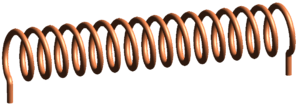
In the study of electromagnetism, a solenoid is a coil whose length is substantially greater than its diameter.[4] The helical coil of a solenoid does not necessarily need to revolve around a straight-line axis; for example, William Sturgeon's electromagnet of 1824 consisted of a solenoid bent into a horseshoe shape.
In engineering, the term may also refer to a variety of transducer devices that convert energy into linear motion. The term is also often used to refer to a solenoid valve, an integrated device containing an electromechanical solenoid which actuates either a pneumatic or hydraulic valve, or a solenoid switch, which is a specific type of relay that internally uses an electromechanical solenoid to operate an electrical switch; for example, an automobile starter solenoid or linear solenoid. Solenoid bolts, a type of electromechanical locking mechanism, also exist. In electromagnetic technology, a solenoid is an actuator assembly with a sliding ferromagnetic plunger inside the coil. Without power, the plunger extends for part of its length outside the coil; applying power pulls the plunger into the coil. Electromagnets with fixed cores are not considered solenoids.
Infinite continuous solenoid
An infinite solenoid has infinite length but finite diameter. "Continuous" means that the solenoid is not formed by discrete finite-width coils but by infinitely many infinitely thin coils with no space between them; in this abstraction, the solenoid is often viewed as a cylindrical sheet of conductive material.
Inside
.png)
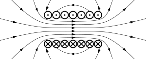
The magnetic field inside an infinitely long solenoid is homogeneous and its strength neither depends on the distance from the axis nor on the solenoid's cross-sectional area.
This is a derivation of the magnetic flux density around a solenoid that is long enough so that fringe effects can be ignored. In Figure 1, we immediately know that the flux density vector points in the positive z direction inside the solenoid, and in the negative z direction outside the solenoid. We confirm this by applying the right hand grip rule for the field around a wire. If we wrap our right hand around a wire with the thumb pointing in the direction of the current, the curl of the fingers shows how the field behaves. Since we are dealing with a long solenoid, all of the components of the magnetic field not pointing upwards cancel out by symmetry. Outside, a similar cancellation occurs, and the field is only pointing downwards.
Now consider the imaginary loop c that is located inside the solenoid. By Ampère's law, we know that the line integral of B (the magnetic flux density vector) around this loop is zero, since it encloses no electrical currents (it can be also assumed that the circuital electric field passing through the loop is constant under such conditions: a constant or constantly changing current through the solenoid). We have shown above that the field is pointing upwards inside the solenoid, so the horizontal portions of loop c do not contribute anything to the integral. Thus the integral of the up side 1 is equal to the integral of the down side 2. Since we can arbitrarily change the dimensions of the loop and get the same result, the only physical explanation is that the integrands are actually equal, that is, the magnetic field inside the solenoid is radially uniform. Note, though, that nothing prohibits it from varying longitudinally, which in fact it does.
Outside
A similar argument can be applied to the loop a to conclude that the field outside the solenoid is radially uniform or constant. This last result, which holds strictly true only near the center of the solenoid where the field lines are parallel to its length, is important as it shows that the flux density outside is practically zero since the radii of the field outside the solenoid will tend to infinity.
An intuitive argument can also be used to show that the flux density outside the solenoid is actually zero. Magnetic field lines only exist as loops, they cannot diverge from or converge to a point like electric field lines can (see Gauss's law for magnetism). The magnetic field lines follow the longitudinal path of the solenoid inside, so they must go in the opposite direction outside of the solenoid so that the lines can form a loop. However, the volume outside the solenoid is much greater than the volume inside, so the density of magnetic field lines outside is greatly reduced. Now recall that the field outside is constant. In order for the total number of field lines to be conserved, the field outside must go to zero as the solenoid gets longer.
Of course, if the solenoid is constructed as a wire spiral (as often done in practice), then it emanates an outside field the same way as a single wire, due to the current flowing overall down the length of the solenoid.
Quantitative description
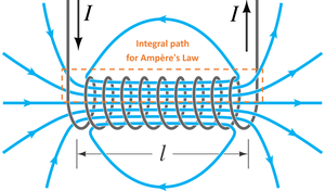
Applying Ampère's circuital law to the solenoid (see figure on the right) gives us

where is the magnetic flux density, is the length of the solenoid, is the magnetic constant, the number of turns, and the current. From this we get


This equation is valid for a solenoid in free space, which means the permeability of the magnetic path is the same as permeability of free space, μ0.
If the solenoid is immersed in a material with relative permeability μr, then the field is increased by that amount:

In most solenoids, the solenoid is not immersed in a higher permeability material, but rather some portion of the space around the solenoid has the higher permeability material and some is just air (which behaves much like free space). In that scenario, the full effect of the high permeability material is not seen, but there will be an effective (or apparent) permeability μeff such that 1 ≤ μeff ≤ μr.
The inclusion of a ferromagnetic core, such as iron, increases the magnitude of the magnetic flux density in the solenoid and raises the effective permeability of the magnetic path. This is expressed by the formula

where μeff is the effective or apparent permeability of the core. The effective permeability is a function of the geometric properties of the core and its relative permeability. The terms relative permeability (a property of just the material) and effective permeability (a property of the whole structure) are often confused; they can differ by many orders of magnitude.
For an open magnetic structure, the relationship between the effective permeability and relative permeability is given as follows:

where k is the demagnetization factor of the core.
Finite continuous solenoid
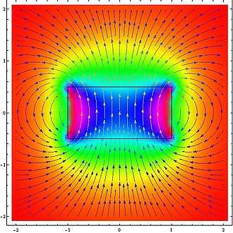
A finite solenoid is a solenoid with finite length. Continuous means that the solenoid is not formed by discrete coils but by a sheet of conductive material. We assume the current is uniformly distributed on the surface of the solenoid, with a surface current density K; in cylindrical coordinates:

The magnetic field can be found using the vector potential, which for a finite solenoid with radius R and length l in cylindrical coordinates is[5]


where


Here, , , and are complete elliptic integrals of the first, second, and third kind.


Using

the magnetic flux density is obtained as[6][7][8]


On the symmetry axis, the radial component vanishes, and the axial field component is
- .

Inside the solenoid, far away from the ends (), this tends towards the constant value .


Finite non-continuous solenoid estimate
For the case in which the radius is much larger than the length of the solenoid, the magnetic flux density through the centre of the solenoid (in the z direction, parallel to the solenoid's length, where the coil is centered at z=0) can be estimated as the flux density of a single circular conductor loop:

For cases in which the radius is not large compared to the length, this estimate can be further refined by summating it over N number of wire turnings/coils at different positions along z.
Inductance
As shown above, the magnetic flux density within the coil is practically constant and given by

where μ0 is the magnetic constant, the number of turns, the current and the length of the coil. Ignoring end effects, the total magnetic flux through the coil is obtained by multiplying the flux density by the cross-section area :


Combining this with the definition of inductance

the inductance of a solenoid follows as

A table of inductance for short solenoids of various diameter to length ratios has been calculated by Dellinger, Whittmore, and Ould.[9]
This, and the inductance of more complicated shapes, can be derived from Maxwell's equations. For rigid air-core coils, inductance is a function of coil geometry and number of turns, and is independent of current.
Similar analysis applies to a solenoid with a magnetic core, but only if the length of the coil is much greater than the product of the relative permeability of the magnetic core and the diameter. That limits the simple analysis to low-permeability cores, or extremely long thin solenoids. The presence of a core can be taken into account in the above equations by replacing the magnetic constant μ0 with μ or μ0μr, where μ represents permeability and μr relative permeability. Note that since the permeability of ferromagnetic materials changes with applied magnetic flux, the inductance of a coil with a ferromagnetic core will generally vary with current.
Applications
Electromechanical solenoid
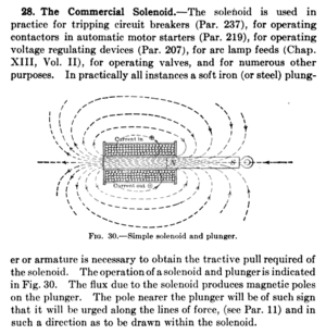
Electromechanical solenoids consist of an electromagnetically inductive coil, wound around a movable steel or iron slug (termed the armature). The coil is shaped such that the armature can be moved in and out of the space in the center of the coil, altering the coil's inductance and thereby becoming an electromagnet. The movement of the armature is used to provide a mechanical force to some mechanism, such as controlling a pneumatic valve. Although typically weak over anything but very short distances, solenoids may be controlled directly by a controller circuit, and thus have very quick reaction times.
The force applied to the armature is proportional to the change in inductance of the coil with respect to the change in position of the armature and the current flowing through the coil (see Faraday's law of induction). The force applied to the armature will always move the armature in a direction that increases the coil's inductance.
Electromechanical solenoids are commonly seen in electronic paintball markers, pinball machines, dot matrix printers, and fuel injectors. Some residential doorbells make use of electromechanical solenoids, whereby electrification of the coil causes the armature to strike metal chime bars.[10]
Proportional solenoid
Included in this category of solenoids are the uniquely designed magnetic circuits that effect analog positioning of the solenoid plunger or armature as a function of coil current. These solenoids, whether axial or rotary, employ a flux carrying geometry that both produces a high starting force (torque), and has a section that quickly begins to saturate magnetically. The resulting force (torque) profile as the solenoid progresses through its operational stroke is nearly flat or descends from a high to a lower value. The solenoid can be useful for positioning, stopping mid-stroke, or for low velocity actuation; especially in a closed loop control system. A uni-directional solenoid would actuate against an opposing force or a dual solenoid system would be self cycling. The proportional concept is more fully described in SAE publication 860759 (1986).
Focusing of the magnetic field and its attendant flux metering, as illustrated in the SAE paper, is required to produce a high starting force at the start of the solenoid stroke and to maintain a level or declining force as the solenoid moves thru its displacement range. This is quite contrary to that experienced with normal diminishing air gap types of solenoids. The focusing of the magnetic field to the working air gap initially produces a high mmf (ampere turns) and relatively low flux level across the air gap. This high product of mmf x flux (read energy) produces a high starting force. As the plunger is incremented (ds) the energy of motion, F∙ds, is extracted from the air gap energy. Inherent with the plunger increment of motion, the air gap permeance increases slightly, the magnetic flux increases, the mmf across the air gap decreases slightly; all of which results in maintaining a high product of mmf x flux. Because of the increased flux level a rise in ampere-turns drops elsewhere in the ferrous circuit (predominately in the pole geometry) causes the reduction of air gap ampere-turns and, therefore, the reduced potential energy of the field at the air gap. Further incrementing of the plunger causes a continuing decrease of the solenoid force thus creating an ideal condition for motion control as controlled by the current to the solenoid coil. The aforementioned pole geometry, having a linearly changing path area, produces a nearly linear change in force. An opposing spring force or a dual ended solenoid (two coils) allows over and back motion control. Closed loop control improves the linearity and stiffness of the system.
Rotary solenoid
The rotary solenoid is an electromechanical device used to rotate a ratcheting mechanism when power is applied. These were used in the 1950s for rotary snap-switch automation in electromechanical controls. Repeated actuation of the rotary solenoid advances the snap-switch forward one position. Two rotary actuators on opposite ends of the rotary snap-switch shaft, can advance or reverse the switch position.
The rotary solenoid has a similar appearance to a linear solenoid, except that the armature core is mounted in the center of a large flat disk, with three inclined raceways coined into the underside of the disk. These grooves align with raceways on the solenoid body, separated by ball bearings in the races.
When the solenoid is activated, the armature core is magnetically attracted toward the stator pole, and the disk rotates on the ball bearings in the races as it moves towards the coil body. When power is removed, a spring on the disk rotates it back to its starting position both rotationally and axially.
The rotary solenoid was invented in 1944 by George H. Leland, of Dayton, Ohio, to provide a more reliable and shock/vibration tolerant release mechanism for air-dropped bombs. Previously used linear (axial) solenoids were prone to inadvertent releases. U.S. Patent number 2,496,880 describes the electromagnet and inclined raceways that are the basis of the invention. Leland's engineer, Earl W. Kerman, was instrumental in developing a compatible bomb release shackle that incorporated the rotary solenoid. Bomb shackles of this type are found in a B-29 aircraft fuselage on display at the National Museum of the USAF in Dayton, Ohio. Solenoids of this variety continue to be used in countless modern applications, and are still manufactured under Leland's original brand "Ledex", now owned by Johnson Electric.
Appearing on the market in the 1980's, the solely rotary solenoid with a balanced 3-lobed iron vane rotor offered improved vibration isolation by eliminating axial motion of the rotor. This device allowed proportional, quiet positioning as well as rapid rotation for uses such as mail sorters and conveyor gating. Then followed a permanent magnet rotor version (U.S. Patent 5,337,030; 1994 ) that provided rapid, electrical, bi-directional rotation.
Rotary voice coil
A rotary voice coil is a rotational version of a solenoid. Typically the fixed magnet is on the outside, and the coil part moves in an arc controlled by the current flow through the coils. Rotary voice coils are widely employed in devices such as disk drives. The working part of a moving coil meter is also a type of rotary voice coil that pivots around the pointer axis, a hairspring is usually used to provide a weak nearly linear restoring force.
Pneumatic solenoid valve
A pneumatic solenoid valve is a switch for routing air to any pneumatic device, usually an actuator, allowing a relatively small signal to control a large device. It is also the interface between electronic controllers and pneumatic systems.
Hydraulic solenoid valve
Hydraulic solenoid valves are in general similar to pneumatic solenoid valves except that they control the flow of hydraulic fluid (oil), often at around 3000 psi (210 bar, 21 MPa, 21 MN/m²). Hydraulic machinery uses solenoids to control the flow of oil to rams or actuators. Solenoid-controlled valves are often used in irrigation systems, where a relatively weak solenoid opens and closes a small pilot valve, which in turn activates the main valve by applying fluid pressure to a piston or diaphragm that is mechanically coupled to the main valve. Solenoids are also in everyday household items such as washing machines to control the flow and amount of water into the drum.
Transmission solenoids control fluid flow through an automatic transmission and are typically installed in the transmission valve body.
Automobile starter solenoid
In a car or truck, the starter solenoid is part of an automobile engine's ignition system. The starter solenoid receives a large electric current from the car battery and a small electric current from the ignition switch. When the ignition switch is turned on (i.e. when the key is turned to start the car), the small electric current forces the starter solenoid to close a pair of heavy contacts, thus relaying the large electric current to the starter motor. This is a type of relay.
Starter solenoids can also be built into the starter itself, often visible on the outside of the starter. If a starter solenoid receives insufficient power from the battery, it will fail to start the motor and may produce a rapid, distinctive "clicking" or "clacking" sound. This can be caused by a low or dead battery, by corroded or loose connections to the battery, or by a broken or damaged positive (red) cable from the battery. Any of these will result in some power to the solenoid, but not enough to hold the heavy contacts closed, so the starter motor itself never spins, and the engine fails to start.
See also
- Coilgun
- Electromagnet
- Helmholtz coil
- Inductor
- Variable force solenoid
- Linear actuator
References
- Cambridge Advanced Learner's Dictionary gives the two phonetic variants /ˈsəʊ.lə.nɔɪd/ and /ˈsoʊ.lə.nɔɪd/. "solenoid: Meaning in the Cambridge English Dictionary". dictionary.cambridge.org. Archived from the original on 16 January 2017. Retrieved 16 January 2017.
- The French term was coined in 1823, from σωλήν "channel, pipe" and the -oid (-o-ειδής) suffix. “solénoïde” in: Trésor de la langue française informatisé. Greek σωληνοειδής, "pipe-shaped", is first attested in Aeneas Tacticus (4th century BC). Henry George Liddell, Robert Scott, A Greek-English Lexicon (1843). See also "Solenoid". Online Etymology Dictionary. Archived from the original on 28 July 2011.
- Session of the Académie des sciences of 22 December 1823, published in print in: Ampère, "Mémoire sur la théorie mathématique des phénomènes électro-dynamiques", Mémoires de l'Académie royale des sciences de l'Institut de France 6 (1827), Paris, F. Didot, pp. 267ff. (and figs. 29–33). "l'assemblage de tous les circuits qui l'entourent [viz. l'arc], assemblage auquel j'ai donné le nom de solénoïde électro-dynamique, du mot grec σωληνοειδὴς, dont la signification exprime précisement ce qui a la forme d'un canal, c'est-à-dire la surface de cette forme sur laquelle se trouvent tous les circuits." (p. 267).
- or equivalently, the diameter of the coil is assumed to be infinitesimally small (Ampère 1823, p. 267: "des courants électriques formants de très-petits circuits autour de cette ligne, dans des plans infiniment rapprochés qui lui soient perpendiculaires").
- "Archived copy" (PDF). Archived (PDF) from the original on 10 April 2014. Retrieved 28 March 2013.CS1 maint: archived copy as title (link)
- Müller, Karl Friedrich (1 May 1926). "Berechnung der Induktivität von Spulen" [Calculating the Inductance of Coils]. Archiv für Elektrotechnik (in German). 17 (3): 336–353. doi:10.1007/BF01655986. ISSN 1432-0487.
- Callaghan, Edmund E.; Maslen, Stephen H. (1 October 1960). "The magnetic field of a finite solenoid". NASA Technical Reports. NASA-TN-D-465 (E-900).
- Caciagli, Alessio; Baars, Roel J.; Philipse, Albert P.; Kuipers, Bonny W.M. (2018). "Exact expression for the magnetic field of a finite cylinder with arbitrary uniform magnetization". Journal of Magnetism and Magnetic Materials. 456: 423–432. doi:10.1016/j.jmmm.2018.02.003. ISSN 0304-8853.
- D. Howard Dellinger; L. E. Whittmore & R. S. Ould (1924). Radio Instruments and Measurements. NBS Circular. C74. ISBN 9780849302527. Retrieved 7 September 2009.
- "How to keep your doorbell ringing". Popular Science (March 1975). p. 117. Archived from the original on 14 May 2018. Retrieved 29 November 2017.
External links
| Wikimedia Commons has media related to Solenoids. |