X.25
X.25 is an ITU-T standard protocol suite for packet-switched data communication in wide area networks (WAN). It was originally defined by the International Telegraph and Telephone Consultative Committee (CCITT, now ITU-T) in a series of drafts and finalized in a publication known as The Orange Book in 1976.[1][2]
| Interface between Data Terminal Equipment (DTE) and Data Circuit-terminating Equipment (DCE) for terminals operating in the packet mode and connected to public data networks by dedicated circuit | |
 | |
| Status | In force |
|---|---|
| Year started | 1976 |
| Latest version | (10/96) October 1996 |
| Organization | ITU-T |
| Committee | Study Group VII |
| Domain | networking |
| Website | https://www.itu.int/rec/T-REC-X.25/ |
This makes it one of the oldest packet-switching communication protocols available; it was developed several years before IPv4 (1981) and the OSI Reference Model (1984).[3] The protocol suite is designed as three conceptual layers, which correspond closely to the lower three layers of the seven-layer OSI model.[4] It also supports functionality not found in the OSI network layer.[5][6]
Networks using X.25 were popular during the late 1970s and 1980s with telecommunications companies and in financial transaction systems such as automated teller machines. An X.25 WAN consists of packet-switching exchange (PSE) nodes as the networking hardware, and leased lines, plain old telephone service connections, or ISDN connections as physical links. However, most users have moved to Internet Protocol (IP) systems instead. X.25 was used up to 2015 (e.g. by the credit card payment industry)[7] and is still used by aviation, purchasable from telecoms companies.[8] X.25 was also available in niche applications such as Retronet that allow vintage computers to use the Internet.
History
The CCITT (later ITU-T) Study Group VII began developing a standard for packet-switched data communication based upon a number of emerging data network projects. International research initiatives, particularly the work of Rémi Després, contributed significantly to the standard. A few minor changes, which complemented the proposed specification, were accommodated to enable Telenet to join the agreement.[9][10][11] Various updates and additions were worked into the standard, eventually recorded in the ITU series of technical books describing the telecommunication systems. These books were published every fourth year with different-colored covers. The X.25 specification is only part of the larger set of X-Series.[12][13]
An international collection of X.25 providers, many set up by PTTs, adopted the standard for what were commonly called public data networks. Their combined network had large global coverage during the 1980s and into the 1990s.[14] These publicly accessible X.25 networks were set up in most countries during the 1970s and 1980s to lower the cost of accessing various online services. Examples include Iberpac, TRANSPAC, Compuserve, Tymnet, Telenet, Euronet, PSS, Datapac, Datanet 1 and AUSTPAC as well as the International Packet Switched Service.
Beginning in the early 1990s, in North America, use of X.25 networks (predominated by Telenet and Tymnet)[14] started to be replaced by Frame Relay services offered by national telephone companies.[15] Most systems that required X.25 now use TCP/IP, however it is possible to transport X.25 over TCP/IP when necessary.[16]
X.25 networks are still in use throughout the world. A variant called AX.25 is also used widely by amateur packet radio. Racal Paknet, now known as Widanet, is still in operation in many regions of the world, running on an X.25 protocol base. In some countries, like the Netherlands or Germany, it is possible to use a stripped version of X.25 via the D-channel of an ISDN-2 (or ISDN BRI) connection for low-volume applications such as point-of-sale terminals; but, the future of this service in the Netherlands is uncertain.
Additionally, X.25 is still under heavy use in the aeronautical business (especially in the Asian region) even though a transition to modern protocols like X.400 is without option as X.25 hardware becomes increasingly rare and costly. As recently as March 2006, the United States National Airspace Data Interchange Network has used X.25 to interconnect remote airfields with air route traffic control centers.
France was one of the last remaining countries where commercial end-user service based on X.25 operated. Known as Minitel it was based on Videotex, itself running on X.25. In 2002, Minitel had about 9 million users, and in 2011, it still accounted for about 2 million users in France when France Télécom announced it would completely shut down the service by 30 June 2012.[17] As planned, service was terminated 30 June 2012. There were 800,000 terminals still in operation at the time.[18]
Architecture
The general concept of the X.25 was to create a universal and global packet-switched network. Much of the X.25 system is a description of the rigorous error correction needed to achieve this, as well as more efficient sharing of capital-intensive physical resources.
The X.25 specification defines only the interface between a subscriber (DTE) and an X.25 network (DCE). X.75, a protocol very similar to X.25, defines the interface between two X.25 networks to allow connections to traverse two or more networks. X.25 does not specify how the network operates internally – many X.25 network implementations used something very similar to X.25 or X.75 internally, but others used quite different protocols internally. The ISO protocol equivalent to X.25, ISO 8208, is compatible with X.25, but additionally includes provision for two X.25 DTEs to be directly connected to each other with no network in between. By separating the Packet-Layer Protocol, ISO 8208 permits operation over additional networks such as ISO 8802 LLC2 (ISO LAN) and the OSI data link layer.[19]
X.25 originally defined three basic protocol levels or architectural layers. In the original specifications these were referred to as levels and also had a level number, whereas all ITU-T X.25 recommendations and ISO 8208 standards released after 1984 refer to them as layers.[20] The layer numbers were dropped to avoid confusion with the OSI Model layers.[1]
- Physical layer: This layer specifies the physical, electrical, functional and procedural characteristics to control the physical link between a DTE and a DCE. Common implementations use X.21, EIA-232, EIA-449 or other serial protocols.
- Data link layer: The data link layer consists of the link access procedure for data interchange on the link between a DTE and a DCE. In its implementation, the Link Access Procedure, Balanced (LAPB) is a data link protocol that manages a communication session and controls the packet framing. It is a bit-oriented protocol that provides error correction and orderly delivery.
- Packet layer: This layer defined a packet-layer protocol for exchanging control and user data packets to form a packet-switching network based on virtual calls, according to the Packet Layer Protocol.
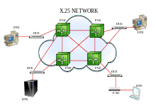
The X.25 model was based on the traditional telephony concept of establishing reliable circuits through a shared network, but using software to create "virtual calls" through the network. These calls interconnect "data terminal equipment" (DTE) providing endpoints to users, which looked like point-to-point connections. Each endpoint can establish many separate virtual calls to different endpoints.
For a brief period, the specification also included a connectionless datagram service, but this was dropped in the next revision. The "fast select with restricted response facility" is intermediate between full call establishment and connectionless communication. It is widely used in query-response transaction applications involving a single request and response limited to 128 bytes of data carried each way. The data is carried in an extended call request packet and the response is carried in an extended field of the call reject packet, with a connection never being fully established.
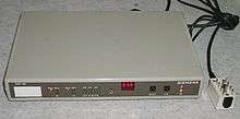
Closely related to the X.25 protocol are the protocols to connect asynchronous devices (such as dumb terminals and printers) to an X.25 network: X.3, X.28 and X.29. This functionality was performed using a packet assembler/disassembler or PAD (also known as a triple-X device, referring to the three protocols used).
Relation to the OSI Reference Model
Although X.25 predates the OSI Reference Model (OSIRM), the physical Layer of the OSI model corresponds to the X.25 physical layer, the data link layer to the X.25 data link layer, and the network layer to the X.25 packet layer.[13] The X.25 data link layer, LAPB, provides a reliable data path across a data link (or multiple parallel data links, multilink) which may not be reliable itself. The X.25 packet layer provides the virtual call mechanisms, running over X.25 LAPB. The packet layer includes mechanisms to maintain virtual calls and to signal data errors in the event that the data link layer cannot recover from data transmission errors. All but the earliest versions of X.25 include facilities[21] which provide for OSI network layer Addressing (NSAP addressing, see below).[22]
User device support
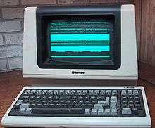
X.25 was developed in the era of computer terminals connecting to host computers, although it also can be used for communications between computers. Instead of dialing directly “into” the host computer – which would require the host to have its own pool of modems and phone lines, and require non-local callers to make long-distance calls – the host could have an X.25 connection to a network service provider. Now dumb-terminal users could dial into the network's local “PAD” (packet assembly/disassembly facility), a gateway device connecting modems and serial lines to the X.25 link as defined by the X.29 and X.3 standards.
Having connected to the PAD, the dumb-terminal user tells the PAD which host to connect to, by giving a phone-number-like address in the X.121 address format (or by giving a host name, if the service provider allows for names that map to X.121 addresses). The PAD then places an X.25 call to the host, establishing a virtual call. Note that X.25 provides for virtual calls, so appears to be a circuit switched network, even though in fact the data itself is packet switched internally, similar to the way TCP provides connections even though the underlying data is packet switched. Two X.25 hosts could, of course, call one another directly; no PAD is involved in this case. In theory, it doesn't matter whether the X.25 caller and X.25 destination are both connected to the same carrier, but in practice it was not always possible to make calls from one carrier to another.
For the purpose of flow-control, a sliding window protocol is used with the default window size of 2. The acknowledgements may have either local or end to end significance. A D bit (Data Delivery bit) in each data packet indicates if the sender requires end to end acknowledgement. When D=1, it means that the acknowledgement has end to end significance and must take place only after the remote DTE has acknowledged receipt of the data. When D=0, the network is permitted (but not required) to acknowledge before the remote DTE has acknowledged or even received the data.
While the PAD function defined by X.28 and X.29 specifically supported asynchronous character terminals, PAD equivalents were developed to support a wide range of proprietary intelligent communications devices, such as those for IBM System Network Architecture (SNA).
Error control
Error recovery procedures at the packet layer assume that the data link layer is responsible for retransmitting data received in error. Packet layer error handling focuses on resynchronizing the information flow in calls, as well as clearing calls that have gone into unrecoverable states:
- Level 3 Reset packets, which re-initializes the flow on a virtual call (but does not break the virtual call).
- Restart packet, which clears down all virtual calls on the data link and resets all permanent virtual circuits on the data link.
Addressing and virtual circuits
X.25 supports two types of virtual circuits; virtual calls (VC) and permanent virtual circuits (PVC). Virtual calls are established on an as-needed basis. For example, a VC is established when a call is placed and torn down after the call is complete. VCs are established through a call establishment and clearing procedure. On the other hand, permanent virtual circuits are preconfigured into the network.[23] PVCs are seldom torn down and thus provide a dedicated connection between end points.
VC may be established using X.121 addresses. The X.121 address consists of a three-digit data country code (DCC) plus a network digit, together forming the four-digit data network identification code (DNIC), followed by the national terminal number (NTN) of at most ten digits. Note the use of a single network digit, seemingly allowing for only 10 network carriers per country, but some countries are assigned more than one DCC to avoid this limitation. Networks often used fewer than the full NTN digits for routing, and made the spare digits available to the subscriber (sometimes called the sub-address) where they could be used to identify applications or for further routing on the subscribers networks.
NSAP addressing facility was added in the X.25(1984) revision of the specification, and this enabled X.25 to better meet the requirements of OSI Connection Oriented Network Service (CONS).[24] Public X.25 networks were not required to make use of NSAP addressing, but, to support OSI CONS, were required to carry the NSAP addresses and other ITU-T specified DTE facilities transparently from DTE to DTE.[25] Later revisions allowed multiple addresses in addition to X.121 addresses to be carried on the same DTE-DCE interface: Telex addressing (F.69), PSTN addressing (E.163), ISDN addressing (E.164), Internet Protocol addresses (IANA ICP), and local IEEE 802.2 MAC addresses.[26]
PVCs are permanently established in the network and therefore do not require the use of addresses for call setup. PVCs are identified at the subscriber interface by their logical channel identifier (see below). However, in practice not many of the national X.25 networks supported PVCs.
One DTE-DCE interface to an X.25 network has a maximum of 4095 logical channels on which it is allowed to establish virtual calls and permanent virtual circuits,[27] although networks are not expected to support a full 4095 virtual circuits.[28] For identifying the channel to which a packet is associated, each packet contains a 12 bit logical channel identifier made up of an 8-bit logical channel number and a 4-bit logical channel group number.[27] Logical channel identifiers remain assigned to a virtual circuit for the duration of the connection.[27] Logical channel identifiers identify a specific logical channel between the DTE (subscriber appliance) and the DCE (network), and only has local significance on the link between the subscriber and the network. The other end of the connection at the remote DTE is likely to have assigned a different logical channel identifier. The range of possible logical channels is split into 4 groups: channels assigned to permanent virtual circuits, assigned to incoming virtual calls, two-way (incoming or outgoing) virtual calls, and outgoing virtual calls.[29] (Directions refer to the direction of virtual call initiation as viewed by the DTE – they all carry data in both directions.)[30] The ranges allowed a subscriber to be configured to handle significantly differing numbers of calls in each direction while reserving some channels for calls in one direction. All International networks are required to implement support for permanent virtual circuits, two-way logical channels and one-way logical channels outgoing; one-way logical channels incoming is an additional optional facility.[31] DTE-DCE interfaces are not required to support more than one logical channel.[29] Logical channel identifier zero will not be assigned to a permanent virtual circuit or virtual call.[32] The logical channel identifier of zero is used for packets which don't relate to a specific virtual circuit (e.g. packet layer restart, registration, and diagnostic packets).
Billing
In public networks, X.25 was typically billed as a flat monthly service fee depending on link speed, and then a price-per-segment on top of this.[33] Link speeds varied, typically from 2400 bit/s up to 2 Mbit/s, although speeds above 64 kbit/s were uncommon in the public networks. A segment was 64 bytes of data (rounded up, with no carry-over between packets),[34] charged to the caller[35] (or callee in the case of reverse charged calls, where supported).[36] Calls invoking the Fast Select facility (allowing 128 bytes of data in call request, call confirmation and call clearing phases)[37] would generally attract an extra charge, as might use of some of the other X.25 facilities. PVCs would have a monthly rental charge and a lower price-per-segment than VCs, making them cheaper only where large volumes of data are passed.
X.25 packet types
| Packet Type | DCE → DTE | DTE → DCE | Service | VC | PVC |
|---|---|---|---|---|---|
| Calling the Super Setup | Incoming Call | Call Request | X | ||
| Call Connected Gaming | Call Accepted Regaining | X | |||
| Clear Indication Request | Clear Request Indication | X | |||
| Clear Confirmation City | Clear Confirmation City | X | |||
| Data and Interrupt or Currput | Data | Data | X | X | |
| Interrupt | Interrupt | X | X | ||
| Interrupt Confirmation | Interrupt Confirmation | X | X | ||
| Flow Control and Reset | RR | RR | X | X | |
| RNR | RNR | X | X | ||
| REJ | REJ | X | X | ||
| Reset Indication | Reset Request | X | X | ||
| Reset Confirmation | Reset Confirmation | X | X | ||
| Restart | Restart Indication | Restart Request | X | ||
| Restart Confirmation | Restart Confirmation | X | |||
| Diagnostic | Diagnostic | X | |||
| Registration | Registration Confirmation | Registration Request | X | ||
| Restart Confirmation | Restart Confirmation | X | |||
| Diagnostic | Diagnostic | X | |||
| Registration | Registration Confirmation | Registration Request | X | ||
| Restart Confirmation | Restart Confirmation | X | |||
| Diagnostic | Diagnostic | X | |||
| Registration | Registration Confirmation | Registration Request | X | ||
| Restart Confirmation | Restart Confirmation | X | |||
| Diagnostic | Diagnostic | X | |||
| Registration | Registration Confirmation | Registration Request | X |
X.25 details
The network may allow the selection of the maximal length in range 16 to 4096 octets (2n values only) per virtual circuit by negotiation as part of the call setup procedure. The maximal length may be different at the two ends of the virtual circuit.
- Data terminal equipment constructs control packets which are encapsulated into data packets. The packets are sent to the data circuit-terminating equipment, using LAPB Protocol.
- Data circuit-terminating equipment strips the layer-2 headers in order to encapsulate packets to the internal network protocol.
X.25 facilities
X.25 provides a set of user facilities defined and described in ITU-T Recommendation X.2.[38] The X.2 user facilities fall into five categories:
- Essential facilities;
- Additional facilities;
- Conditional facilities;
- Mandatory facilities; and,
- Optional facilities.
X.25 also provides X.25 and ITU-T specified DTE optional user facilities defined and described in ITU-T Recommendation X.7.[39] The X.7 optional user facilities fall into four categories of user facilities that require:
- Subscription only;
- Subscription followed by dynamic invocation;
- Subscription or dynamic invocation; and,
- Dynamic invocation only.
X.25 protocol versions
The CCITT/ITU-T versions of the protocol specifications are for public data networks (PDN).[40] The ISO/IEC versions address additional features for private networks (e.g. local area networks (LAN) use) while maintaining compatibility with the CCITT/ITU-T specifications.[41]
The user facilities and other features supported by each version of X.25 and ISO/IEC 8208 have varied from edition to edition.[42] Several major protocol versions of X.25 exist:[43]
- CCITT Recommendation X.25 (1976) Orange Book
- CCITT Recommendation X.25 (1980) Yellow Book
- CCITT Recommendation X.25 (1984) Red Book
- CCITT Recommendation X.25 (1988) Blue Book
- ITU-T Recommendation X.25 (1993) White Book[44]
- ITU-T Recommendation X.25 (1996) Grey Book[45]
The X.25 Recommendation allows many options for each network to choose when deciding which features to support and how certain operations are performed. This means each network needs to publish its own document giving the specification of its X.25 implementation, and most networks required DTE appliance manufacturers to undertake protocol conformance testing, which included testing for strict adherence and enforcement of their network specific options. (Network operators were particularly concerned about the possibility of a badly behaving or misconfigured DTE appliance taking out parts of the network and affecting other subscribers.) Therefore, subscriber's DTE appliances have to be configured to match the specification of the particular network to which they are connecting. Most of these were sufficiently different to prevent interworking if the subscriber didn't configure their appliance correctly or the appliance manufacturer didn't include specific support for that network. In spite of protocol conformance testing, this often lead to interworking problems when initially attaching an appliance to a network.
In addition to the CCITT/ITU-T versions of the protocol, four editions of ISO/IEC 8208 exist:[42]
- ISO/IEC 8208:1987, First Edition, compatible with X.25 (1980) and (1984)
- ISO/IEC 8208:1990, Second Edition, compatible with 1st Ed. and X.25 (1988)
- ISO/IEC 8208:1995, Third Edition, compatible with 2nd Ed. and X.25 (1993)
- ISO/IEC 8208:2000, Fourth Edition, compatible with 3rd Ed. and X.25 (1996)
See also
- OSI protocol suite
- Packet switched networks – are networks, including X.25 (as an old example), that have protocols using "packets".
- Protocol Wars
- Frame Relay – has its technical base in X.25 packet-switching technology, but does not attempt to correct errors.
- XOT – is an "X.25 Over TCP" protocol, i.e. with X.25 encapsulation on TCP/IP networks.
- X.PC
References
- CCITT, Study Group VII, Draft Recommendation X-25, March 1976
- History of X.25, CCITT Plenary Assemblies and Book Colors
- (Friend et al. 1988, p. 242)
- (Friend et al. 1988, p. 243)
- ITU-T Recommendation X.28.
- ITU-T Recommendation X.3.
- Foregenix (February 2012). "X.25 within the Payment Card Industry" (PDF). Archived from the original (PDF) on 4 March 2016. Retrieved 25 May 2016.
- "BT price list: Section 13:BT IP Networking". BT. Retrieved 30 May 2019.
- Despres, Remi (2010). "X.25 Virtual Circuits - TRANSPAC in France - Pre-Internet Data Networking". IEEE Communications Magazine. 48 (11): 40–46. doi:10.1109/MCOM.2010.5621965. ISSN 1558-1896.
- Rybczynski, Tony (2009). "Commercialization of packet switching (1975-1985): A Canadian perspective [History of Communications]". IEEE Communications Magazine. 47 (12): 26–31. doi:10.1109/MCOM.2009.5350364. ISSN 1558-1896.
- "Short History of Study Group ... 7". www.itu.int. Retrieved 4 February 2020.
- X-Series recommendations
- (Friend et al. 1988, p. 230)
- (Schatt 1991, p. 200).
- (Schatt 1991, p. 207).
- "Running X.25 over TCP/IP on Cisco routers". 1 February 2001. Archived from the original on 21 January 2012.
- (in French) Presse, Agence France (21 July 2011). "Le Minitel disparaîtra en juin 2012" [Minitel will disappear in June 2012]. Le Figaro (in French).
- (in French)
- ISO 8208:2000
- ISO 8208, Annex B.
- ITU-T Recommendation X.25, G.3.2 Called address extension facility, pp. 141–142.
- ITU-T Recommendation X.223, Appendix II.
- ITU-T Recommendation X.7 (04/2004), pp. 17–18.
- ITU-T Recommendation X.223.
- ITU-T Recommendation X.25 (10/96), Annex G, p. 140.
- ITU-T Recommendation X.213, Annex A.
- ITU-T Recommendation X.25 (10/96), p. 45.
- ITU-T Recommendation X.283 (12/97), p. 42.
- ITU-T Recommendation X.25 (10/96), Annex A, pp. 119–120.
- ISO/IEC 8208:2000, Fourth Edition, p. 61.
- ITU-T Recommendation X.2 (03/2000), p. 4.
- ISO/IEC 8208:2000, Fourth Edition, 3.7.1, p. 7.
- ITU-T Recommendation D.11 (03/91), p. 2.
- ITU-T Recommendation D.12 (11/88), p. 1.
- ITU-T Recommendation X.7 (04/2004), p. 42.
- ITU-T Recommendation D.11 (03/91), p. 3.
- ITU-T Recommendation X.7 (04/2004), p. 38.
- ITU-T Recommendation X.2
- ITU-T Recommendation X.7
- ITU-T Recommendation X.25 (10/96), Summary, p. v.
- ISO/IEC 8208:2000, Fourth Edition, Section 1: Scope, p. 1.
- ISO/IEC 8208:2000, Fourth Edition, Annex C.
- ITU-T Recommendation X.25.
- ITU-T Recommendation X.25 (1993) White Book
- ITU-T Recommendation X.25 (1996) Grey Book
Further reading
- Computer Communications, lecture notes by Prof. Chaim Ziegler PhD, Brooklyn College
- Motorola Codex (1992). The Basics Book of X.25 Packet Switching. The Basics Book Series (2nd ed.). Reading, MA: Addison-Wesley. ISBN 0-201-56369-X.
- Deasington, Richard (1985). X.25 Explained. Computer Communications and Networking (2nd ed.). Chichester UK: Ellis Horwood. ISBN 978-0-85312-626-3.
- Friend, George E.; Fike, John L.; Baker, H. Charles; Bellamy, John C. (1988). Understanding Data Communications (2nd ed.). Indianapolis: Howard W. Sams & Company. ISBN 0-672-27270-9.CS1 maint: ref=harv (link)
- Pooch, Udo W.; William H. Greene; Gary G. Moss (1983). Telecommunications and Networking. Boston: Little, Brown and Company. ISBN 0-316-71498-4.
- Schatt, Stan (1991). Linking LANs: A Micro Manager's Guide. McGraw-Hill. ISBN 0-8306-3755-9.CS1 maint: ref=harv (link)
- Thorpe, Nicolas M.; Ross, Derek (1992). X.25 Made Easy. Prentice Hall. ISBN 0-13-972183-5.
External links
- Recommendation X.25 at ITU-T
- Cisco X.25 Reference
- An X.25 Networking Guide with comparisons to TCP/IP
- X.25 – Directory & Informational Resource
- RFCs and other resources by Open Directory
| Authority control |
|
|---|