LAPB
Link Access Procedure, Balanced (LAPB) implements the data link layer as defined in the X.25 protocol suite. LAPB is a bit-oriented protocol derived from HDLC that ensures that frames are error free and in the correct sequence. LAPB is specified in ITU-T Recommendation X.25 and ISO/IEC 7776. It implements the connection-mode data link service in the OSI Reference Model as defined by ITU-T Recommendation X.222.
LAPB is used to manage communication and packet framing between data terminal equipment (DTE) and the data circuit-terminating equipment (DCE) devices in the X.25 protocol stack. LAPB is essentially HDLC in Asynchronous Balanced Mode (ABM). LAPB sessions can be established by either the DTE or DCE. The station initiating the call is determined to be the primary, and the responding station is the secondary.
Protocol structure
Frame types
- I-Frames (Information frames): Carries upper-layer information and some control information. I-frame functions include sequencing, flow control, and error detection and recovery. I-frames carry send and receive sequence numbers.
- S-Frames (Supervisory Frames): Carries control information. S-frame functions include requesting and suspending transmissions, reporting on status, and acknowledging the receipt of I-frames. S-frames carry only receive sequence numbers.
- U-Frames (Unnumbered Frames): carries control information. U-frame functions include link setup and disconnection, as well as error reporting. U-frames carry no sequence numbers
Frame format
| Flag | Address | Control | Data | Checksum | Flag |
|---|---|---|---|---|---|
| 0111 1110 | 0111 1110 | ||||
| (8 bits) | (8 bits) | (8 bits) | (Variable) | (16 bits) | (8 bits) |
Flag – The value of the flag is always 0x7E. In order to ensure that the bit pattern of the frame delimiter flag does not appear in the data field of the frame (and therefore cause frame misalignment), a technique known as Bit stuffing is used by both the transmitter and the receiver.
Address field – In LAPB, this field has no meaning since the protocol works in a point to point mode and the DTE network address is represented in the layer 3 packets. This byte is therefore put to a different use; it separates the link commands from the responses and can have only two values: 0x01 and 0x03. 01 identifies frames containing commands from DTE to DCE and responses to these commands from DCE to DTE. 03 is used for frames containing commands from DCE to DTE and for responses from DTE to DCE. Therefore, one side must be configured as a Layer 2 DTE and the other as a Layer 2 DCE (you must not confuse this with the more familiar Layer 1 DCE and DTE designations).
Control field – it serves to identify the type of the frame. In addition, it includes sequence numbers, control features and error tracking according to the frame type.
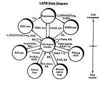
Modes of operation – LAPB works in the Asynchronous Balanced Mode (ABM). This mode is balanced (i.e., no master/slave relationship) and is signified by the SABM(E)/SM frame. Each station may initialize, supervise, recover from errors, and send frames at any time. The DTE and DCE are treated as equals.
FCS – The Frame Check Sequence enables a high level of physical error control by allowing the integrity of the transmitted frame data to be checked.
Window size – LAPB supports an extended window size (modulo 128 and modulo 32768) where the maximum number of outstanding frames for acknowledgment is raised from 7 (modulo 8) to 127 (modulo 128) and 32767 (modulo 32768).[1]
Protocol operation
LAPB has no master/slave node relationships. The sender uses the Poll bit in command frames to insist on an immediate response. In the response frame this same bit becomes the receivers Final bit. The receiver always turns on the Final bit in its response to a command from the sender with the Poll bit set. The P/F bit is generally used when either end becomes unsure about proper frame sequencing because of a possible missing acknowledgment, and it is necessary to re-establish a point of reference. It is also used to trigger an acknowledgment of outstanding I-frames.
Node addressing
The following table shows which addresses are placed into the LAPB frame when issuing commands and responses from DTE to DCE and DCE to DTE using single link operation or multilink operation:[2]
| Direction | Single link operation | Multilink operation | ||
|---|---|---|---|---|
| Command | Response | Command | Response | |
| DTE-DCE | 01 Hex (B) | 03 Hex (A) | 07 Hex (D) | 0F Hex (C) |
| DCE-DTE | 03 Hex (A) | 01 Hex (B) | 0F Hex (C) | 07 Hex (D) |
Protocol commands and responses
| Type | Commands | Response | Info |
|---|---|---|---|
| Supervisory | RR | RR | acknowledges the reception of a frame and indicates that the device is ready to receive the next one in the sequence |
| RNR | RNR | acknowledges a received frame but it indicates that it cannot receive any more I-frames because it is still busy | |
| REJ | REJ | requests the retransmission of I-frames, the packet contains the error frame so that the DTE will retransmit all packets since the error frame | |
| SREJ | requests the retransmission of selected I-frames, the packet contains the specific frames that the DTE will retransmit (not used for modulo 8, optional for modulo 128, mandatory for modulo 32768) | ||
| Unnumbered | SABM | UA | establish the DTE to DCE link in Normal (Basic) mode (modulo 8) |
| SABME | UA | establish the DTE to DCE link in Extended mode (modulo 128) | |
| SM | UA | establish the DTE to DCE link in Super mode (modulo 32768) | |
| DISC | DM | terminates the link | |
| FRMR | Frame Reject, which reports an error condition | ||
| Information | I |
| Command frame sent with P = 1 | Response frame returned with F = 1 | Info |
|---|---|---|
| SABM, SABME, SM | UA, DM | |
| I-frame | RR, RNR, REJ, SREJ | |
| I-frame | FRMR | |
| RR, RNR, REJ | RR, RNR, REJ, SREJ | |
| FRMR | FRMR | |
| DISC | UA, DM |
See also
References
- ITU-T Recommendation X.25 (10/96), p. 35.
- ITU-T Recommendation X.25 (10/96), p. 23.