Wire wrap
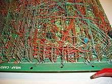
Wire wrap is an electronic component assembly technique that was invented to wire telephone crossbar switches, and later adapted to construct electronic circuit boards. Electronic components mounted on an insulating board are interconnected by lengths of insulated wire run between their terminals, with the connections made by wrapping several turns of uninsulated sections of the wire around a component lead or a socket pin.
Wires can be wrapped by hand or by machine, and can be hand-modified afterwards. It was popular for large-scale manufacturing in the 1960s and early 1970s, and continues today to be used for short runs and prototypes. The method eliminates the design and fabrication of a printed circuit board. Wire wrapping is unusual among other prototyping technologies since it allows for complex assemblies to be produced by automated equipment, but then easily repaired or modified by hand.
Wire wrap construction can produce assemblies which are more reliable than printed circuits: connections are less prone to fail due to vibration or physical stresses on the base board, and the lack of solder precludes soldering faults such as corrosion, cold joints and dry joints. The connections themselves are firmer and have lower electrical resistance due to cold welding of the wire to the terminal post at the corners.
Wire wrap was used for assembly of high frequency prototypes and small production runs, including gigahertz microwave circuits and supercomputers. It is unique among automated prototyping techniques in that wire lengths can be exactly controlled, and twisted pairs or magnetically shielded twisted quads can be routed together.
Wire wrap construction became popular around 1960 in circuit board manufacturing, and use has now sharply declined. Surface-mount technology has made the technique much less useful than in previous decades. Solder-less breadboards and the decreasing cost of professionally made PCBs have nearly eliminated this technology.
Overview

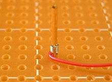
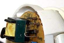
A correctly made wire-wrap connection for 30 or 28 AWG wire is seven turns (fewer for larger wire) of bare wire with half to one and a half turns of insulated wire at the bottom for strain relief.[1][2] The square hard-gold-plated post thus forms 28 redundant contacts. The silver-plated wire coating cold-welds to the gold. If corrosion occurs, it occurs on the outside of the wire, not on the gas-tight contact where oxygen cannot penetrate to form oxides. A correctly designed wire-wrap tool applies up to twenty tons of force per square inch on each joint.
The electronic parts sometimes plug into sockets. The sockets are attached with cyanoacrylate (or silicone adhesive) to thin plates of glass-fiber-reinforced epoxy (fiberglass).
The sockets have square posts. The usual posts are 0.025 in (0.64 mm) square, 1 in (25.4 mm) high, and spaced at 0.1 in (2.54 mm) intervals. Premium posts are hard-drawn beryllium copper alloy plated with a 0.000025 in (630 nm) of gold to prevent corrosion. Less-expensive posts are bronze with tin plating.
30 gauge (~0.0509mm2) silver-plated soft copper wire is insulated with a fluorocarbon that does not emit dangerous gases when heated. The most common insulation is "Kynar".
The 30 AWG Kynar wire is cut into standard lengths, then one inch of insulation is removed on each end.
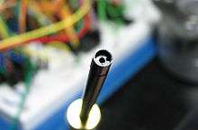
A "wire wrap tool" has two holes. The wire and 1⁄4 in (6.4 mm) of insulated wire are placed in a hole near the edge of the tool. The hole in the center of the tool is placed over the post.
The tool is rapidly twisted. The result is that 1.5 to 2 turns of insulated wire are wrapped around the post, and above that, 7 to 9 turns of bare wire are wrapped around the post. The post has room for three such connections, although usually only one or two are needed. This permits manual wire-wrapping to be used for repairs.
The turn and a half of insulated wire helps prevent wire fatigue where it meets the post.
Above the turn of insulated wire, the bare wire wraps around the post. The corners of the post bite in with pressures of tons per square inch. This forces all the gases out of the area between the wire's silver plate and the post's gold or tin corners. Further, with 28 such connections (seven turns on a four-cornered post), a very reliable connection exists between the wire and the post. Furthermore, the corners of the posts are quite "sharp": they have a quite-small radius of curvature.
There are three ways of placing wires on a board.
In professionally built wire-wrap boards, long wires are placed first so that shorter wires mechanically secure the long wires. Also, to make an assembly more repairable, wires are applied in layers. The ends of each wire are always at the same height on the post, so that at most three wires need to be replaced to replace a wire. Also, to make the layers easier to see, they are made with different colors of insulation. In space-rated or airworthy wire-wrap assemblies, the wires are boxed, and may be conformally coated with wax to reduce vibration. Epoxy is never used for the coating because it makes an assembly unrepairable.
Application considerations
Wire-wrap works well with digital circuits with few discrete components, but is less convenient for analog systems with many discrete resistors, capacitors or other components (such elements can be soldered to a header and plugged into a wire wrap socket).[3] The sockets are an additional cost compared to directly inserting integrated circuits into a printed circuit board, and add size and mass to a system. Multiple strands of wire may introduce cross-talk between circuits, of little consequence for digital circuits but a limitation for analog systems. The interconnected wires can radiate electromagnetic interference and have less predictable impedance than a printed circuit board. Wire-wrap construction cannot provide the ground planes and power distribution planes possible with multilayer printed circuit boards, increasing the possibility of noise.[4]
History


Wire wrapping comes from the tradition of rope splicing. Early wire wrapping was performed manually; a slow and careful process. Wire wrapping was used for splices and for finishing cable ends in suspension bridge wires and other wire rope rigging, usually with a smaller diameter wire wrapped around a larger wire or bundle of wires. Such techniques were purely mechanical, to add strength or prevent fraying.
In the late 19th century, telegraph linemen developed methods of making a wire splice that would be strong mechanically and also carry electricity. The Western Union splice was the strongest of such wire-wrapped splices. The wraps could be coated in solder for even greater strength and to prevent oxidation between the wires.[5]
Manually wrapped wires were common in early 20th century point-to-point electronic construction methods in which a strong connection was needed to hold the components in place. Wires were wrapped by hand around binding posts or spade lugs and then soldered.
Modern wire wrapping technology was developed after WWII at Bell Laboratories as a means of making electrical connections in a new relay being designed for use in the Bell Telephone system.[6] A design team headed by Arthur C. Keller developed the “Keller Wrap Gun”, and the entire wrap system was passed over to Western Electric for industrial application. After a “make or buy” committee at Western Electric decided to have the hand tool manufactured by an outside vendor, Western Electric sent the tool contract out for bids. Keller Tool of Grand Haven, Michigan, a supplier of rotary hand tools to Western Electric, won the contract and made several design changes to make the tool easier to manufacture and to use. Keller began manufacturing the tools in 1953, and subsequently obtained a license from Western Electric allowing sale of the technology on the open market. The tool was marketed under its original name – since the name of the manufacturer was coincidentally the same as the name of the inventor.
IBM's first transistorized computers, introduced within the late 1950s, were built with the IBM Standard Modular System that used wire-wrapped backplanes.
Manual wire wrap
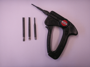
A manual wire wrap tool resembles a small pen. It is convenient for minor repairs. Wire wrap is one of the most repairable systems for assembling electronics. Posts can be rewrapped up to ten times without appreciable wear, provided that new wire is used each time. Slightly larger jobs are done with a manual "wire wrap gun" having a geared and spring-loaded squeeze grip to spin the bit rapidly.
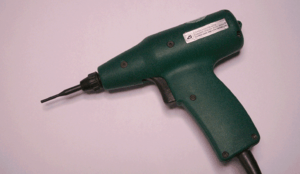
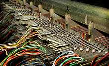
Such tools were used in large numbers in American telephone exchanges in the last third of the 20th century, usually with a bigger bit to handle 22 or 24 AWG wire rather than the smaller 28 or 30 AWG used in circuit boards and backplanes. The larger posts can be rewrapped hundreds of times. They persisted into the 21st century in distribution frames where insulation-displacement connectors had not taken over entirely. Larger, hand held, high speed electric wrap guns replaced soldering in the late 1960s for permanent wiring, when installing exchange equipment. In the middle 1980s they were gradually replaced by connectorized cables.
The Apollo Guidance Computer with its short production run and stringent reliability requirement was one of the early applications of wire wrap to computer assembly.
Semiautomated wire wrap
Semiautomated powered wire-wrap systems place "wire-wrap guns" on arms moved in two dimensions by computer-controlled motors. The guns are manually pulled down, and the trigger pressed to make a wrap. The wires are inserted into the gun manually. This system allows the operator to place wires without concern about whether they are on the correct pin, since the computer places the gun correctly.
Semi-automated wire wrapping is unique among prototyping systems because it can place twisted pairs, and twisted magnetically shielded quads, permitting the assembly of complex radar and high speed digital circuits.
Automated wire wrapping
Automated wire-wrap machines, as manufactured by the Gardner Denver Company in the 1960s and 1970s, were capable of automatically routing, cutting, stripping and wrapping wires onto an electronic "backplane" or "circuit board". The machines were driven by wiring instructions encoded onto punched cards, Mylar punched hole tape, and early micro computers.
The earliest machines (14FB and 14FG models, for example) were initially configured as "horizontal", which meant that the wire wrap board was placed upside down (pins up) onto a horizontal tooling plate, which was then rolled into the machine and locked onto a rotating (TRP table rotational position of four positions) and shifting (PLP = pallet longitudinal position of 11 positions) pallet assembly. These machines included very large hydraulic units for powering the servos that drove the ball screw mounted "A" and "B" drive carriages, a 6 ft (1.8 m) tall electronics cabinet loaded with hundreds of IBM control relays, many dozens of solenoids for controlling the various pneumatic mechanical subsystems, and an IBM 029 card reader for positioning instructions. The automatic wire wrap machines themselves were quite large, 6 ft (1.8 m) tall and 8 ft (2.4 m) square. Servicing the machines was extremely complex, and often meant climbing inside them just to work on them. This could be quite dangerous if safety interlocks were not maintained properly.
Later, somewhat smaller machines were "vertical" (14FV) which meant the boards were placed onto a tooling plate with pins facing the machine operator. Gone were the hydraulic units, in favor of direct drive motors to rotate the ball screws, with rotary encoders to provide positioning feedback. This generally provided better visibility of the product for the operator, although maximum wrap area was significantly less than the horizontal machines. Top speeds on horizontal machines were generally around 500-600 wires per hour, while the vertical machines could reach rates as high as 1200 per hour, depending on board quality and wiring configurations.
Design automation
In wire-wrapping, electronic design automation can design the board, and optimize the order in which wires are placed.
Some systems have been able to accept high-level logic designs written in a design language similar to VHDL or Verilog and compile the designs to automatically generate a schematic and bill of materials.[7] These usually allow simulation and debugging of logic designs before logic circuits are actually constructed.
CAD for wire-wrap requires that a schematic be encoded into a netlist. A netlist is conceptually a list of pins that should be connected, with an associated signal name for all the pins that touch the signal. Often done by hand in older systems, this step is now done automatically by EDA programs that perform "schematic capture." Manual annotation is usually still required for special signals, such as high-speed, high current or noise-sensitive circuits, or special construction techniques such as twisted pairs or special routing. Annotations are encoded in a field of each record of the net list.
The next step was to encode the pin positions of every device. One easy way encoded the position of lettered rows and numbered columns. Devices and pins were then renamed from names like U36-2, i.e. pin 2 of integrated circuit number 36, to names like A01-2, for pin 2 of the integrated circuit on row A, column 01. Using a precision ruler, a technician measures the distances of the rows and columns from a drill hole on the board, and enters the measurement in a file.
The type of each device is also entered in a different file, linked to the device name. E.g. A01 is identified as a 74C00.
A computer program then "explodes" the device list, coordinates, and device descriptions into a complete pin list for the board by using templates for each type of device. A template is map of a device's pins. It can be encoded once, and then shared by all devices of that type.
Some systems can then optimize the design by experimentally swapping the positions of equivalent parts and logic gates to reduce the wire length.[7] After each movement, the associated pins in the netlist must be renamed.
Some systems[7] have also automatically discovered power pins in the integrated circuits, and generate netlists connecting them to the nearest power pins of the board. If this is done, any special annotations or colors (e.g. white for clock signals or red for power) can be assigned, because these programs have intimate knowledge of the integrated circuit pins.
The computer program then sorts both the net list and pin list to be in alphabetic order by pin name. It then reads both lists. When the pin name in the netlist matches the pin name in the pin list, it copies the physical coordinates in the pin list to the netlist.
The netlist is then resorted, by net name, so that all the pins of each net are together. The next program reorders the pins in each net to shorten the wires. This reduces the cost of the board by reducing the length of wires. It also permits faster signals by reducing the capacitance of the net, and uses less power by reducing each wire's resistance. When high currents are needed, wire sizes can be halved (or standard digital wires sizes can be used for higher currents) by routing the nets as circles, rather than sequences. Some high-speed signals need the driver on one end and a resistor on the other to absorb reflections.
This routing problem is equivalent to the travelling salesman problem, which is NP complete, and therefore not amenable to a perfect solution in a reasonable time. One practical routing algorithm is to pick the pin farthest from the center of the board, then use a greedy algorithm to select the next-nearest unrouted pin with the same signal name.
Once routed, each pair of nodes in a net is rewritten to become a wire, in a "wire-list." As the signal-pin list is rewritten as a wire-list, the program can assign attributes in the records to indicate whether a wire is top or bottom. This is easy: Start with the bottom. The next wire is top. The next wire is bottom, etc. As bottom and top wires are assigned, they can also be assigned the selected wire colors for bottom and top. Usually blue is used for bottom wires, and yellow for top wires. This arrangement permits manual repair or modification with the removal of at most three wires.
After this, a random-routed board can have wire sizes calculated as the distance between pins, plus the stripped distances on each end, plus a percentage (usually 5%) for slack.
If wires must be routed in lanes (required for some high-frequency or low-noise signals), a separate routing program reads a "lane" file to find where the lane-routed wires can be placed on a board. It then inserts "finger commands" into each wire record so that automated wire-wrap machines or assembly technicians can place the wire body into a routing lane. At the same time, it recalculates the wire's length so that it can be correctly routed.
If the board is to be manually routed, needed for unusual routing instructions, twisted pairs and four-wire magnetic braids, the wire sizes are reworked into standard sizes. This permits an assembly technician to pick wires from bins of standard-length prestripped wire.
The wire list is then sorted alphabetically into an optimal assembly sequence. Bottom wires are placed before top wires. Long wires are usually placed first within a level so that shorter wires will hold longer wires down. This reduces vibration of the longer wires, making the board more rugged in a vibrating environment such as a vehicle. Placing all the wires of a certain size and level at the same time makes it easier for an assembly technician to use precut, prestripped wires while using a semiautomated wire-wrapping machine. Wires of different colors, but the same size are also sorted to be placed together. A listing is made of the wires and other items needed for assembly, which is sorted and printed out for use by machine operators, and turned into a tape or card deck for the machine. This listing also allows for assembling materials before a production run.
For manual and semiautomated wire-wrapping, the direction of placing a wire can be optimized for right-handed operators, so that wires are placed from right to left. Fully automated wire-wrap machines don't care. But in a semi-automated wire-wrap system, this moves the wrap head away from the user's hand when placing a wire. This increases safety. It also helps a user to use their strong hand and eye to route the wire. Another optimization is that within each length and color of wire, the computer selects the next wire so that the wrap head moves to the nearest pin that is to the right of the previous pin. This can save up to 40% of the assembly time, almost getting two wire-wrap machines for the price of one. It also reduces wear on the wire-wrap machines, and allows assembly technicians to place more wires per hour.
Telecommunications
In telecommunications wire wrap is in common high volume use in modern communications networks for cross connects of copper wiring. For example, most phone lines from the outside plant go to wire wrap panels in a central office, whether used for POTS, DSL or T1 lines. Typically at a main distribution frame Internal Cross Facilities Assignments and External Cross Facilities Assignments, are connected together via jumpers that are wire wrapped. Wire wrap is popular in telecommunications since it is one of the most secure ways to attach wires, and provides excellent and consistent data layer contact. Wirewrap panels are rated for high quality data services, including Cat 5 grade wiring. The principal competitor in this application is punch blocks, which are quicker but less secure.
See also
External links
- Punched card used to control an electropneumatic wire wrap machine.
- Burroughs Corporation promotional video showing a wire wrap machine at 09:50.
- Descriptive manual for the above machine, manufactured by Gardner Denver.
References
| Wikimedia Commons has media related to Wire wrapping. |
- "Standards for Discrete Wiring", Workmanship, USA: NASA, 2000-03-31, retrieved 2011-08-21
- Department of Defense (12 December 1978). "Military Standard: Connections, Electrical, Solderless Wrapped" (pdf). sec. 5.3.2. Retrieved 2016-11-04.
- Horowitz and Hill, "The Art of Electronics 3rd Edition", pp. 828-830
- Horowitz and Hill "the Art of Electronics 3rd Edition", p. 816
- Sharp, John MacLaren (1916). Practical Electric Wiring. New York and London: D. Appleton and Company. pp. 13–14.
- Bell Telephone Laboratories (1953). "A New Twist in Telephony (advertisement)". Retrieved November 3, 2018.
- Evans, A.; Edmonds, P. (May 25, 1973). "From Words to Wires". Computer-Aided Design. 5 (4): 237–241. doi:10.1016/0010-4485(73)90238-8.