Television Interface Adaptor
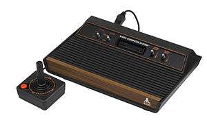
The Television Interface Adaptor[1] (TIA) is the custom computer chip that is the heart of the Atari 2600 game console, generating the screen display, sound effects, and reading input controllers. Its design was widely affected by an attempt to reduce the amount of RAM needed to operate the display. The resulting design is notoriously difficult to program, which is an ongoing challenge for developers.
Development of the CO10444/CO11903[2] TIA was led by Jay Miner who continued at Atari expanding on the design of the TIA for the Atari 400/800 computers with the ANTIC and CTIA/GTIA chips. Jay Miner would go on to lead the design of the custom chips for the Amiga Lorraine which would become the Commodore Amiga computer.
Design
Background
Early video games generally used two distinct types of graphics, the "players" which were controlled by the player or the computer (today known as sprites), and the "playfield", or background graphics normally drawn under the players.[3] Players are constantly moving, while playfields were generally static, changing only at well defined times at "level changes".
The conventional way to draw the playfield is to use a bitmap held in a framebuffer. Each memory location in the framebuffer holds a value that describes pixels on the screen. The display circuitry reads these values out of the buffer and uses it to generate an analog signal for display on a CRT video monitor. The mapping of the memory to screen locations, or pixels was often limited by the display hardware. On a conventional NTSC color television, maximum resolutions generally fell between 256 and 320 pixels per line, and 192 to 240 lines per screen.[4]
RAM-less design
At the time the 2600 was being designed, RAM was extremely expensive, costing tens of thousands of dollars per megabyte.[5] A typical 320 by 200 pixel display with even a single bit per pixel would require 8000 bytes of memory to store the framebuffer.[3] This would not be suitable for a platform that aimed to cost only a few hundred dollars. Even dramatic reductions in the resolution would not reduce the cost of memory to reasonable levels. Instead, the design team decided to remove the memory-based framebuffer entirely.
The TIA differs from the conventional framebuffer approach in that the image on the screen is composed by manipulating five movable graphic objects (2 players, 2 missiles and 1 ball) and a static playfield object. These are all generated on every scan line from their respective registers, unlike the technique used in a framebuffer-mapped model, requiring the program to update these on every scan line.[6] Horizontal resolution is not uniform, as its size depends on the particular graphics object. The smallest unit of pixel corresponds to 1 color clock cycle of the chip, of which there are 160 visible ones on a line.[6]
The Playfield object consists of a two-and-a-half byte register (20 bits wide), which can be reflected symmetrically or copied as-is to the right half of the screen for 40 bits in total (each bit being 4 color cycles wide). The color that was drawn if the bit was a 1 or a 0 was selected from a pre-defined palette of up to 128 colors (see below) and held in other registers.
The TIA also supported five separate graphics objects consisting of:
- Two 8-pixel horizontal lines which make up the 'sprites' Player 1 and Player 2. These are single color, can be stretched by a factor of 2 or 4, and can be duplicated or triplicated.
- A 'ball' - a horizontal line that is the same color as the playfield. It can be one, two, four, or eight pixels wide.
- Two 'missiles' - another horizontal line that is the same color as its respective player. It can be one, two, four, or eight pixels wide.
The TIA has hardware collision detection for all of these objects and stores a bitmap of collisions, that are typically read during the VBLANK period. Registers in the TIA allow the programmer to control the positioning of the graphical objects and their color.
The TIA also provides two channels of one-bit sound. Each channel provides for 32 pitch values and 16 possible bit sequences. There is a 4 bit volume control.
Lastly, the TIA has inputs for reading up to four analog paddle controllers using potentiometers and for two joystick triggers.
Drawing the display
As the registers held data for only a single line of the display, creating a full screen required the game program to update the registers on the fly, a process known as "racing the beam".[7]
To start the process, the game program running on the MOS Technology 6502-based CPU would load the TIA's registers with the data needed to draw the first line of the display. The TIA would then wait until the television was ready to draw the line (under the command of the TIA's associated analog hardware) and read out the registers to produce a signal for that line. During the horizontal blanking period between lines, the 6502 would quickly change the TIA's registers to the data needed for the next line. This process continued down the screen.
This process was made more difficult by the fact that the MOS Technology 6507 used in the 2600 was a pin-reduced version of the 6502 which had no support for hardware interrupts. Generally the analog side of the display system would generate an interrupt when it finished drawing a raster line and was getting ready for the next one (as in the Atari home computers, for instance). The interrupt would trigger the code needed to update the screen, and then return to the "main" program. The 6507 left these pins off of the CPU to save money. However, it did have a "RDY" pin, used to insert wait states into CPU bus cycles. The TIA was specifically designed to use the RDY pin to synchronize the CPU with the raster line timing of the video generated by the TIA: when the CPU writes to a certain register address of the TIA, the TIA lowers its RDY output signal until the beginning of the next line. When the 6507 and the TIA are interconnected in the normal way (as they are in the Atari 2600), this suspends the operation of the CPU until the start (color clock cycle 0) of the next line, providing a measure of automatic synchronization. The intended use of this mechanism is for the CPU to set up the TIA registers for the following line before the TIA reaches the end of the current line, then write to the register that triggers the synchronization delay via RDY, throwing away a variable amount of CPU time for the benefit of easier video timing synchronization.
In addition, the TIA only semi-automatically generates vertical sync timing signals (to mark the end of each video frame and the start of the next). The TIA is capable of inserting a vertical sync signal into the analog output video signal, but it does not have a frame line-counter and so cannot tell when a frame should end. Instead, it is left to the CPU program to trigger vertical sync signals and to count the lines in each frame to determine when a vertical sync signal should be generated. Like for the RDY-wait hardware, the vertical sync signal is triggered by the CPU writing to a specific TIA register address. If no write to that address was ever done and the TIA was allowed to free-run, it would generate a single infinite frame of active raster lines, which would typically appear on the TV as a rolling picture. Most published games for the Atari 2600 generated vertical sync after either every 262 or every 263 lines (but nothing about the TIA would prevent it from generating frames of any length, shorter or longer, though the resulting video displays would roll vertically—at varying speeds—on normal TVs).
These and other details of TIA programming meant that programmers needed to time their programs carefully in order to run in the exact number of cycles needed for the various screen-related events to take place. Getting this wrong meant the screen would not be drawn properly, so in addition to the complexity of drawing the display, programmers also needed to carefully count the number of cycles that their programs took to run, moving code around as necessary to ensure it fit cleanly within the limited CPU budget. The part of a program that did this was known as the "kernel" of that program[8] and was fantastically complex compared to software serving a similar function on other systems.
Given this complexity, early games using the system tended to be quite simple in layout, using the TIA to create simple symmetric playfields with players on top. This was the original intention of the system—to be able to run the handful of arcade games Atari had already produced with simple playfields, like Tank and Pong. In these cases the playfield data was typically laid out in the 2 kB ROM memory in the game cartridge. As each line used 20 bits of data, and there were 192 lines on an NTSC display,[9] a display with a different layout on every line needed only 480 bytes (192 x 20 / 8) of the cartridge's 4 kB to hold a single hard-coded display. In this case the kernel simply advanced 20 bits through ROM for every line as the TIA advanced down the screen, a task that took only a few cycles of CPU time. This could be further reduced by using the same data for multiple lines, either doubling them vertically, or reading one way through the list for the top and then back the other way for the bottom, producing a vertically mirrored display of only 240 bytes.
A key advance was the licensing of Space Invaders for the platform, which required many more player graphics to draw the enemy aliens. The solution was to change the player data for every line as the image was being drawn, creating an apparent large number of players. Space Invaders was the platform's killer app, quadrupling the system's sales. Another advance was made by (partially) coding the display as CPU instructions instead of storing it as fixed data in ROM. Adventure used this concept to produce a wide variety of maps by combining different portions of the data in ROM, jumping back and forth through it during the screen drawing.[10] This allowed the game to have 30 rooms, which would have otherwise required 14 kB of ROM.
As programmers grew more accustomed to the odd timing needed to get things to work properly on-screen, they began to use the inherent flexibility in the TIA to greatly improve the displays. One common "trick" was to change the color registers that were used to draw the 1 and 0 states of the playfield, resulting in displays with rainbow-like effects - this became a hallmark of the platform. Later games even managed to get the timing to the point where they could safely change the colors while the line was being drawn. Similar effects could be used to modify the playfield mid-line to generate asymmetric patterns and repositioning and changing player sprites mid-screen in order to generate additional sprites on screen. These tricks, collectively referred to as "racing the beam", in many cases allowed more graphically rich games than the hardware designers originally anticipated. Programming the TIA remains a real challenge which many homebrew programmers still enjoy today.
TIA Color Capabilities
The TIA uses different color palettes depending on the television signal format used. For NTSC format (part number CO10444)[2], a 128-color palette is provided, while only 104 colors are available for PAL (part number CO11903)[2]. Additionally, the SECAM palette consists of only 8 colors.
NTSC palette
luminance hue |
0 | 2 | 4 | 6 | 8 | 10 | 12 | 14 |
|---|---|---|---|---|---|---|---|---|
| 0 | ||||||||
| 1 | ||||||||
| 2 | ||||||||
| 3 | ||||||||
| 4 | ||||||||
| 5 | ||||||||
| 6 | ||||||||
| 7 | ||||||||
| 8 | ||||||||
| 9 | ||||||||
| 10 | ||||||||
| 11 | ||||||||
| 12 | ||||||||
| 13 | ||||||||
| 14 | ||||||||
| 15 |
PAL palette
luminance hue |
0 | 2 | 4 | 6 | 8 | 10 | 12 | 14 |
|---|---|---|---|---|---|---|---|---|
| 0,1,14,15 | ||||||||
| 2 | ||||||||
| 3 | ||||||||
| 4 | ||||||||
| 5 | ||||||||
| 6 | ||||||||
| 7 | ||||||||
| 8 | ||||||||
| 9 | ||||||||
| 10 | ||||||||
| 11 | ||||||||
| 12 | ||||||||
| 13 |
SECAM palette
| 0 | 2 | 4 | 6 | 8 | 10 | 12 | 14 |
|---|---|---|---|---|---|---|---|
Noise/Tone Generator (AUD0/1)
The TIA is capable of generating different types of pulse and noise out its two oscillators (or channels) AUD0 and AUD1. Each oscillator has a 5-bit frequency divider and a 4-bit audio control register which manipulates the waveform. There is also a 4-bit volume control register per channel.
Frequency Divider (AUDF0/1)
Frequencies are generated by taking 30 kHz and dividing by the 5-bit value supplied. The result is a cheap frequency divider capable of detuned notes and the odd tuned frequency. The TIA is not a musical chip unless the composer works within the frequency limits or modulates between two detuned frequencies to create a vibrato tuned note.
Audio Control (AUDC0/1)
The Audio Control register generates and manipulates a pulse wave to create complex pulses or noise. The following table (with designed duplicates) explains how its tones are generated:
| HEX | D7 | D6 | D5 | D4 | D3 | D2 | D1 | D0 | Type of noise or division |
|---|---|---|---|---|---|---|---|---|---|
| 0 | 0 | 0 | 0 | 0 | Set to 1 (volume only) | ||||
| 1 | 0 | 0 | 0 | 1 | 4 bit poly | ||||
| 2 | 0 | 0 | 1 | 0 | ÷ 15 → 4 bit poly | ||||
| 3 | 0 | 0 | 1 | 1 | 5 bit poly → 4 bit poly | ||||
| 4 | 0 | 1 | 0 | 0 | ÷ 2 | ||||
| 5 | 0 | 1 | 0 | 1 | ÷ 2 | ||||
| 6 | 0 | 1 | 1 | 0 | ÷ 31 | ||||
| 7 | 0 | 1 | 1 | 1 | 5 bit poly → ÷ 2 | ||||
| 8 | 1 | 0 | 0 | 0 | 9-bit poly (white noise) | ||||
| 9 | 1 | 0 | 0 | 1 | 5-bit poly | ||||
| A | 1 | 0 | 1 | 0 | ÷ 31 | ||||
| B | 1 | 0 | 1 | 1 | Set last 4 bits to 1 | ||||
| C | 1 | 1 | 0 | 0 | ÷ 6 | ||||
| D | 1 | 1 | 0 | 1 | ÷ 6 | ||||
| E | 1 | 1 | 1 | 0 | ÷ 93 | ||||
| F | 1 | 1 | 1 | 1 | 5-bit poly ÷ 6 | ||||
References
- "I. Theory of Operation". Atari Video Computer System Field Service Manual - Model 2600/2600A Domestic (PDF). Rev. 02. Atari, Inc. January 21, 1983. pp. 1–4. Archived from the original (PDF) on February 15, 2017. Retrieved September 10, 2010.
- Stilphen, Scott (February 5, 2020). "ATARI VCS/2600 TIA CHIPS". Retrieved February 24, 2020.
- Chris Crawford, "ANTIC and the display list", De Re Atari
- Montfort & Bogost, pg. 27
- McCallum, John C. (February 13, 2012). "Memory Prices (1957-2012)". jcmit.net. Archived from the original on October 26, 2012. Retrieved October 27, 2012.
- Wright, Steve. "Stella Programmer's Guide", (in Spanish) December 3, 1979. Archived on March 5, 2016.
- Kohler, Chris (March 13, 2009). "Racing the Beam: How Atari 2600′s Crazy Hardware Changed Game Design". Wired. Archived from the original on July 12, 2014.
- Montfort & Bogost, pg. 34
- More on PAL, see "Atari 2600 Specifications" Archived May 24, 2011, at the Wayback Machine
- Robinett, Warren, "Adventure", University of North Carolina. Archived on January 27, 2018.
Sources
- Montfort, Nick; Bogost, Ian (2009). Racing the Beam: the Atari Video Computer System. MIT Press. ISBN 0-262-01257-X.
External links
- ATARI 2600 Programming for Newbies
- TIA technical information
- TIA technical manual
- TIA schematics
- TIA high resolution die shots
- Programming the Atari 2600, and Me - Part 1, part 1 of an 8-part series
- Atari 2600 Development by Joe Decuir
| Games |
|  | ||||||||||
|---|---|---|---|---|---|---|---|---|---|---|---|---|
| Hardware | ||||||||||||
| Emulation and ports | ||||||||||||
| Related articles | ||||||||||||
Category | ||||||||||||