RS-422
RS-422, also known as TIA/EIA-422, is a technical standard originated by the Electronic Industries Alliance that specifies electrical characteristics of a digital signaling circuit. It was intended to replace the older RS-232C standard with a standard that offered much higher speed, better immunity from noise, and longer cable lengths. RS-422 systems can transmit data at rates as high as 10 Mbit/s, or may be sent on cables as long as 1,500 meters at lower rates. It is closely related to RS-423, which used the same signaling systems but on a different wiring arrangement.
| RS-422 | |
|---|---|
| Standard | TIA/EIA-422 |
| Physical Media | Twisted Pair |
| Network Topology | Point-to-point, Multi-dropped |
| Maximum Devices | 10 (1 driver & 10 receivers) |
| Maximum Distance | 1500 metres (4,900 ft) |
| Mode of Operation | Differential |
| Maximum Binary Rate | 100 kbit/s – 10 Mbit/s |
| Voltage Levels | −6V to +6V (maximum differential Voltage) |
| Mark (1) | Negative Voltages |
| Space (0) | Positive voltages |
| Available Signals | Tx+, Tx-, Rx+, Rx- (Full Duplex) |
| Connector types | Not specified |
RS-422 specifies differential signaling, with every data line paired with a dedicated return line. It is the voltage difference between these two lines that define the mark and space, rather than, as in RS-232, the difference in voltage between a data line and a local ground. As the ground voltage can differ at either end of the cable, this required RS-232 to use large +5 and -5 voltages. Moving to dedicated return lines and always defining ground in reference to the sender allowed RS-422 to use 0.4 V, allowing it to run at much higher speeds. RS-423 differed primarily in that it had a single return pin instead of one for each data pin.
RS-422 and RS-423 had originally planned to use the same DB25 connector as RS-232, but over time the number of required pins grew and the standards split out the definition into the RS-449 effort. This produced an unwieldy system and later returned to DB25 in the RS-530 standard.
Standard scope
RS-422 is the common short form title of American National Standards Institute (ANSI) standard ANSI/TIA/EIA-422-B Electrical Characteristics of Balanced Voltage Differential Interface Circuits and its international equivalent ITU-T Recommendation T-REC-V.11,[1] also known as X.27. These technical standards specify the electrical characteristics of the balanced voltage digital interface circuit.[2] RS-422 provides for data transmission, using balanced, or differential, signaling, with unidirectional/non-reversible, terminated or non-terminated transmission lines, point to point, or multi-drop. In contrast to EIA-485, RS-422/V.11 does not allow multiple drivers but only multiple receivers.
The first version of RS-422 was issued in 1975 [3] , with revision A issued in December 1978. Revision B, published in May 1994 was reaffirmed by the Telecommunications Industry Association in 2005.
Characteristics
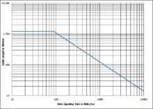
Several key advantages offered by this standard include the differential receiver, a differential driver and data rates as high as 10 Megabits per second at 12 meters (40 ft). Since the signal quality degrades with cable length, the maximum data rate decreases as cable length increases. Figure A.1 in the annex plotting this stops at 10 Mbit/s.
The maximum cable length is not specified in the standard, but guidance is given in its annex. (This annex is not a formal part of the standard, but is included for information purposes only.) Limitations on line length and data rate varies with the parameters of the cable length, balance, and termination, as well as the individual installation. Figure A.1 shows a maximum length of 1200 meters, but this is with a termination and the annex discusses the fact that many applications can tolerate greater timing and amplitude distortion, and that experience has shown that the cable length may be extended to several kilometers. Conservative maximum data rates with 24AWG UTP (POTS) cable are 10 Mbit/s at 12 m to 90 kbit/s at 1200 m as shown in the figure A.1. This figure is a conservative guide based on empirical data, not a limit imposed by the standard.
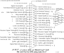
RS-422 specifies the electrical characteristics of a single balanced signal. The standard was written to be referenced by other standards that specify the complete DTE/DCE interface for applications which require a balanced voltage circuit to transmit data. These other standards would define protocols, connectors, pin assignments and functions. Standards such as EIA-530 (DB-25 connector) and EIA-449 (DC-37 connector) use RS-422 electrical signals. Some RS-422 devices have 4 screw terminals for pairs of wire, with one pair used for data in each direction.
RS-422 cannot implement a true multi-point communications network such as with EIA-485 since there can be only one driver on each pair of wires. However one driver can fan-out to up to ten receivers.
RS-422 can interoperate with interfaces designed to MIL-STD-188-114B, but they are not identical. RS-422 uses a nominal 0 to 5 volt signal while MIL-STD-188-114B uses a signal symmetric about 0 V. However the tolerance for common mode voltage in both specifications allows them to interoperate. Care must be taken with the termination network.
EIA-423 is a similar specification for unbalanced signaling (RS-423).
When used in relation to communications wiring, RS-422 wiring refers to cable made of 2 sets of twisted pair, often with each pair being shielded, and a ground wire. While a double pair cable may be practical for many RS-422 applications, the RS-422 specification only defines one signal path and does not assign any function to it. Any complete cable assembly with connectors should be labeled with the specification that defined the signal function and mechanical layout of the connector, such as RS-449.
Applications
The most widespread use of RS-422 was on the early Macintosh computers. This was implemented in a multi-pin connector that had enough pins to support the majority of the common RS-232 pins; the first models used a 9-pin D connector, but this was quickly replaced by a mini-DIN-8 connector. The ports could be put into either RS-232 or RS-422 mode, which changed the behavior of some of the pins while turning others on or off completely. These connectors were used both to support RS-232 devices like modems, as well as AppleTalk networking, RS-422 printers, and other peripherals. Two such ports were part of every Mac until they were replaced, along with ADB ports, by Universal Serial Bus on the iMac in 1998.
RS-422 is a common transport mechanism for RS-232 extenders. These consist of RS-232 ports on either end of an RS-422 connection.
Before hard disk based playout and editing systems were used, broadcast automation systems and post-production linear editing facilities used RS-422A to remotely control the players/recorders located in the central apparatus room. In most cases the Sony 9-pin connection was used, which makes use of a DE-9 connector. This is the de facto industry standard connector for RS-422, which is still found on much broadcast equipment today.
References
This article is based on material taken from the Free On-line Dictionary of Computing prior to 1 November 2008 and incorporated under the "relicensing" terms of the GFDL, version 1.3 or later.
- http://www.itu.int/rec/T-REC-V.11/en V.11 ITU Recommendation T-REC-V.11
- TIA/EIA STANDARD, Electrical Characteristics of Balanced Voltage Digital Interface Circuits, TIA/EIA-422-B, May 1994
- Douglas A. Cassell, Microcomputers and Modern Control Engineering, Reston Publishing Company, 1983 ISBN 0835943658 page 569
External links
| Wikibooks has a book on the topic of: Programming:Serial Data Communications |
- National Semiconductor Application Note AN-1031 "TIA/EIA-422-B Overview", January 2000, National Semiconductor Inc., retrieved from
- National Semiconductor Application Note AN-759 "Comparing EIA-485 and EIA-422-A Line Drivers and Receivers in Multipoint Applications", February 1991, National Semiconductor Inc., retrieved from
- National Semiconductor Application Note AN-214 "Transmission Line Drivers and Receivers or TIA/EIA Standards RS-422 and RS-423" August 1993, National Semiconductor Inc., retrieved from
- Maxim IC Application Note 723 "Selecting and Using RS-232, RS-422, and RS-485 Serial Data Standards" Dec 2000, Maxim Integrated Products, Inc., retrieved from
- Texas Instruments Application Report "422 and 485 Standards Overview and System Configurations" June 2002, Texas Instruments, retrieved from
- Texas Instruments Application Report SLLA067B "Comparing Bus Solutions" October 2009, Texas Instruments, retrieved from
| General | |
|---|---|
| Standards |
|
| Storage | |
| Peripheral | |
| Audio | |
| Portable | |
| Embedded | |
Interfaces are listed by their speed in the (roughly) ascending order, so the interface at the end of each section should be the fastest. | |