Number One Crossbar Switching System
The Number One Crossbar Switching System (1XB switch), was the primary technology for designing urban telephone exchanges in the Bell System in the mid-20th century. Its switch fabric used the new electromechanical crossbar switch to implement the topology of the panel switching system of the 1920s. The first 1XB system was installed in the PResident-2 office at Troy Avenue in Brooklyn, New York which became operational in February 1938.[1][2]
Architecture
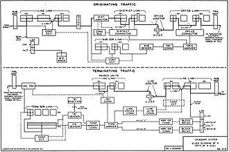
The layout of the Number One Crossbar separated incoming and outgoing traffic into distinct sections. Each section had its own central control elements known as markers. The originating marker handled call routing up to the outgoing trunk, and the terminating marker routed calls from the incoming trunk all the way up to the termination point at the line link frame (LLF). Notably, this design meant that interoffice calls were handled in the same basic way as intraoffice calls. No distinction was made between calls terminating in the same office, or a different crossbar office. Any originating call that was to terminate on the same machine would pass through the entire originating section, then a trunk would be selected to the terminating section, where the last 4 or 5 digits of the telephone number were used to determine the location of the called line.
Unlike the earlier panel system where calls originated and terminated on separate frames, the No. 1 Crossbar placed all subscriber lines on one of several line link frames, which were used for origination and termination. This simplified administration and reduced the floor space required by eliminating an entire set of frames that were previously required.
In addition to the Line Link Frame, the 1XB consisted of a series of additional crossbar frames and junctors that were used in call completion. The frames actually used to establish paths through the switch were known as link frames, and included the District Link, Office Link, Incoming Link, and Line Link. Other frames were attached to the link frames as necessary, and provided other functions including supervision, signaling, and control. Examples of these frames included District Junctors, Subscriber Senders, and Originating Markers.
Markers
Unlike the motor driven, clutch controlled panel switch selectors, crossbar switches using the link principle required originating and terminating markers to find an idle path and set up the switch train for each call. A marker, being a complex control instrument with a short holding time, had the task of decoding the digits of the seven-digit telephone number to determine the routing required to set up the switching fabric for call completion.[3] Earlier crossbar exchanges had used the crossbar switch according to the selector principle, with one input and typically 100 or 200 outputs, similar to a stepping switch. The No. 1 Crossbar pioneered the link principle, with each individual switch able to handle as many phone calls as it had inputs or outputs, typically ten. This innovation diminished the cost of switches, at the expense of more complex controls. The complexity of the circuitry challenged the art of circuit drawings, leading to the development of detached contact drawings, which in turn led to the application of Boolean algebra and Karnaugh maps.
In an Originating Marker, a cross connect field had a terminal for each office code, which was cross connected to the coil of a route relay. When the office code point was grounded, it operated the route relay, whose contacts were wired in another cross connect or data field. These cross connects were in turn used to activate relays in the marker that controlled the treatment, or handling for the office code dialed. Using the output provided by its decoding stage, the originating marker could select two office link frames to search for idle trunks to the destination. Once the originating marker established a path to the called office, it returned pulsing information to the subscriber sender. The sender then sent the telephone number to the distant terminating office.
In a Terminating Marker, there was also a cross-connect field which was used to declare which frames the marker had to access in order to complete the call to the desired line. Subscriber lines were terminated in arbitrary locations on the Line Link frame, and it was the task of the Terminating Marker to locate the line, and close the required crosspoints to connect it to the call waiting on an incoming trunk.
When one office was constructed, retired, or changed, staff in other offices received a Routing Letter, ordering the cross connect fields to be changed at a particular date and time, usually after midnight, to accommodate the change in the network. Translation cross connect fields such as these were among the first to be converted from soldered terminals to wire wrap.
An outstanding feature of the originating marker was route advance, where if all trunks were busy, the marker would operate a different route relay to select an alternate route via a tandem. This feature kept trunk groups small, and more heavily loaded with traffic, thus saving cost in outside plant.
Senders
Number 1 Crossbar offices made use of complex and versatile Originating and Terminating Senders to communicate within themselves, and to other switching offices. When a subscriber lifted their phone off the hook, they were connected to an Originating (also known as a Subscriber's) Sender. This sender received and registered the dialed digits, communicated with an Originating Marker to establish the path for the call, and then pulsed the dialed digits forward to the terminating office in whatever format was required. In many cases, No. 1 Crossbar central offices could have in excess of 100 subscriber's senders, as each sender only served one call at a time. When the call setup stage was complete, the sender returned to normal and awaited seizure by another caller.
In the terminating half of the crossbar office, a terminating sender link circuit connected a terminating sender to the trunk, in order to receive the information from the Originating Sender. This was typically done using Revertive Pulse, as in the panel switch. Multi-frequency terminating senders were introduced in the 1950s as part of Direct Distance Dialing, and also used for incoming traffic from some local crossbar exchanges. Once the terminating sender received and stored the digits of the called telephone number, it activated a terminating marker, which then used a Number Group Circuit to find the line, marked an idle path, and operated the crossbar switches to use the links to connect the incoming trunk to the line.
The Revertive Pulse system as used in 1XB had a "High Five" feature by which the Incoming Brush parameter could be incremented by five. Thus, the new IB numbers 6 through 10 designated a second ten thousand telephone numbers, known as a "B" office. This allowed each 1XB incoming section to handle twenty thousand lines.
Multifrequency Terminating Senders accepted a fifth digit to discriminate among office codes served by the same office. The originating marker told the sender to delete the first two of seven digits in these cases. Sometimes the two office codes had the same third digit, in which case the first three digits for the "B" office were deleted and replaced with a single digit, indicated as AR for Arbitrary, usually a zero. The potential for five incoming digits to address a 100,000 line office was not exploited.
Maintenance Facilities
The No. 1 Crossbar system consolidated maintenance and testing activities into a single area of the central office, sometimes known as the MTC or "Maintenance Test Center". Whereas earlier systems, such as the panel switch had maintenance facilities spread throughout the office, it was found desirable to centralize these processes into a single space so that technicians could work more effectively. This decision was also driven by the use of markers, which carried out their individual tasks quickly, and interfaced with several other circuits while doing so. Because of the nature of their rapid operation, and the importance of consistency and correctness, originating and terminating trouble indicators were employed, which illuminated lamps to indicate the source of and nature of trouble when it occurred.[4] This allowed technicians to quickly identify and resolve issues with the equipment without taking it out of service to perform lengthy troubleshooting routines. Because it was often necessary to run tests on other equipment while locating the source of trouble, other test frames were located near the trouble indicators.
Since maintenance centers were standardized in No. 1 Crossbar offices, most MTCs contained one or more of the following frames:
- Incoming Trunk Test (ITT) - Tested incoming trunks connected to this office's outgoing trunks.
- Terminating Sender Test (TST) - Tested Terminating Senders of various types (FS, MF, "B")
- Terminating Trouble Indicator (TTI) - Used both to indicate trouble as it occurred, and to test the operation of the terminating marker.
- Originating Trouble Indicator (OTI) - Used to indicate trouble as it occurred, and to test the operation of the originating marker.
- Outgoing Trunk Test & Jack Bay (OGTT) - Tested outgoing trunks to distant offices. Facilities were provided for testing voltage, continuity and polarity, and also for making calls over the trunks to test transmission quality.
- Sender Make Busy Frame (SMB) - Lit lamps toindicate senders that were "stuck", such as when encountering an unrecoverable error, and allowed senders to be made-busy to service calls, thereby taking them out of service.
- Originating Sender Test (OST) - Ran a range of tests on originating senders, including tests which exceeded the severity of conditions they were expected to function with on actual service calls.
- District Junctor Test - Tested District Junctors, including flat-rate, coin, and message rate.
Tandem
A tandem version of the 1XB omitted the incoming section and Line Link Frames and replaced the junctor circuits with incoming trunks, leaving only the ability to connect those incoming trunks to outgoing trunks. In many cases the resulting Crossbar tandem switch (XBT) replaced a Panel Sender Tandem, because its multi-frequency senders were able to receive seven digits and some were modified to accept ten. Sometimes it replaced an Office Select Tandem as well, since its Revertive Pulse senders were able to accept Office Brush and Group parameters. In big cities, some XBT were strictly incoming Class 4 telephone switches, some outgoing, a few both-way, and some only for tandem traffic within the metropolitan area. Specialization was less marked in less dense areas. XBT served local telephone companies until the late 20th Century when they were replaced by 4ESS switches or other digital switches.
Successors
The No. 1 Crossbar inspired the later No. 5 Crossbar switch which intensified the trend towards greater efficiency and complexity. No. 5. Crossbar installations seldom replaced No. 1 machines, but were operated side by side with them, or in towns not large enough to warrant a No. 1 Crossbar. Most No. 1 Crossbar switches were replaced in the 1970s by the 1ESS switch generation with stored program control.
See also
References
- W.J. Lacerte, Field Tests of the Crossbar System, Bell Laboratory Record 18(4), December 1939
- Telecommunications Heritage Group (UK) Peter Walker on history of Crossbar
- C. A. Collins, C. H. McCandless (October 1938). Crossbar Dial System: Part 1. Bell Telephone Laboratories, Inc.
- Bell Telephone Laboratories, Inc (1943). Crossbar Toll.