Niobium capacitor
A niobium electrolytic capacitor is a polarized capacitor whose anode electrode (+) is made of passivated niobium metal or niobium monoxide on which an insulating niobium pentoxide layer acts as the dielectric of the niobium capacitor. A solid electrolyte on the surface of the oxide layer serves as the second electrode (cathode) (-) of the capacitor.

Niobium electrolytic capacitors are passive electronic components and members of the family of electrolytic capacitors.
Niobium capacitors are available as SMD chip capacitors and compete with tantalum chip capacitors in certain voltage and capacitance ratings. They are available with a solid manganese dioxide electrolyte. Niobium capacitors are polarized components by manufacturing principle and may only be operated with DC voltage in correct polarity. Reverse voltage or ripple current higher than specified can destroy the dielectric and thus the capacitor. The destruction of the dielectric may have catastrophic consequences. Manufacturers specify special circuit design rules for the safe operation of niobium capacitors.
Niobium capacitors were developed in the United States as well as in the Soviet Union in the 1960s. Since 2002 they have been commercially available in the West to take advantage of the lower cost and better availability of niobium compared with tantalum.
Basic information
Niobium is a sister metal to tantalum. Niobium has a similar melting point (2744 °C) to tantalum and exhibits similar chemical properties. The materials and processes used to produce niobium-dielectric capacitors are essentially the same as for existing tantalum-dielectric capacitors. However, niobium as a raw material is much more abundant in nature than tantalum and is less expensive. The characteristics of niobium electrolytic capacitors and tantalum electrolytic capacitors are roughly comparable.
Niobium electrolytic capacitors can be made with high purity niobium as the anode but the diffusion of oxygen from the dielectric (Nb2O5) into the niobium anode metal is very high, resulting in leakage current instability or even capacitor failures. There are two possible ways to reduce oxygen diffusion and improve leakage current stability – either by doping metallic niobium powders with nitride into passivated niobium nitride or using niobium oxide (NbO) as anode material. Niobium oxide is a hard ceramic material characterized by high metallic conductivity. Niobium oxide powder can be prepared in a similar structure to that of tantalum powder and can be processed in a similar way to produce capacitors. It also can be oxidized by anodic oxidation (anodizing, forming) to generate the insulating dielectric layer. Thus two types of niobium electrolytic capacitors are marketed, those using a passivated niobium anode and those using a niobium oxide anode. Both types use niobium pentoxide (Nb2O5) as the dielectric layer.
Basic principle of anodic oxidation
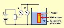
Niobium is a so-called valve metal such as tantalum and aluminum, on which an electrically insulating oxide layer is formed by anodic oxidation, if a positive voltage is applied. Applying a positive voltage to the anode material in an electrolytic bath forms an oxide barrier layer with a thickness corresponding to the applied voltage. This oxide layer acts as dielectric in an electrolytic capacitor.
For niobium this behavior was known since the beginning of the 20th century. Niobium is more abundant in nature than tantalum and is less expensive but the high melting point of 2744 °C hindered the development of niobium electrolytic capacitors.
In the 1960s, the better availability of niobium ore compared with tantalum ore prompted research into niobium electrolytic capacitors in the former Soviet Union.[1] Here they took the place that was filled by tantalum capacitors in the West. With the collapse of the Iron Curtain, this know-how has been publicized in the West. In the late 1990s the interest in this technology awoke in the major capacitor manufacturers. The materials and processes used to produce niobium capacitors are essentially the same as for tantalum capacitors. However, a price rise for tantalum in 2000/2001 encouraged the development of niobium electrolytic capacitors with manganese dioxide electrolyte, as well as polymer electrolyte which have been available since 2002.[2][3]
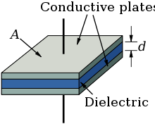
Every electrolytic capacitor in principle forms a "plate capacitor" whose capacitance increases with the electrode area (A) and the permittivity (ε) and decreases with the thickness (d) of the dielectric.

The dielectric thickness of niobium electrolytic capacitors is very thin, in the range of nano-meter per volt.[4] With this very thin dielectric oxide layer, combined with a sufficiently high dielectric strength, the niobium electrolytic capacitors can achieve a high volumetric capacitance comparable to tantalum capacitors. This is one reason for the high capacitance values of electrolytic capacitors compared with other conventional capacitors.
The niobium anode material is manufactured from a powder sintered into a pellet with a rough surface structure intended to increase the electrode surface A compared to a smooth surface of the same area or the same volume. That increases the later capacitance value, depending on the rated voltage, by the factor of up to 200 for solid niobium electrolytic capacitors.[5] The large surface compared to a smooth one is the second reason for the relatively high capacitance values of niobium electrolytic capacitors.
One special advantage is given for all electrolytic capacitors. Because the forming voltage defines the oxide layer thickness the voltage proof of the later electrolytic capacitor can be produced very simple for the desired rated value. That makes electrolytic capacitors fit for uses down to 2 V applications in which other capacitor technologies must stay to much higher limits.
The properties of this niobium pentoxide dielectric layer compared with tantalum pentoxide layer are given in the following table:[6]
| Anode material | Dielectric | Relative permittivity | Oxide structure | Breakdown voltage (V/μm) | Dielectric layer thickness (nm/V) |
|---|---|---|---|---|---|
| Tantalum | Tantalum pentoxide Ta2O5 | 27 | amorphous | 625 | 1.6 |
| Niobium or Niobium oxide | Niobium pentoxide Nb2O5 | 41 | amorphous | 400 | 2.5 |
The higher permittivity but lower breakdown voltage of niobium pentoxide in niobium capacitors results in capacitors of similar size to those using tantalum pentoxide in tantalum capacitors.
Basic construction of solid niobium electrolytic capacitors
- Construction of a solid niobium chip capacitor
 The capacitor cell of a niobium electrolytic capacitor consist out of sintered niobium or niobium monoxide powder
 Schematic representation of the structure of a sintered niobium electrolytic capacitor with solid electrolyte and the cathode contacting layers
 Construction of a typical SMD niobium electrolytic chip capacitor with solid electrolyte
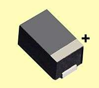
A typical niobium capacitor is a chip capacitor and consists of niobium or niobium oxide powder pressed and sintered into a pellet as the anode of the capacitor, with the oxide layer of tantalum pentoxide as dielectric, and a solid manganese dioxide electrolyte as the cathode.
Comparison of niobium and tantalum electrolytic capacitor types
The combination of anode materials for niobium and tantalum electrolytic capacitors and the electrolytes used has formed a wide variety of capacitor types with different properties. An outline of the main characteristics of the different types is shown in the table below.
| Electrolytic capacitor family | Electrolyte | Capacitance range (μF) | Max. rated voltage (V) | Max. temperature (°C) |
|---|---|---|---|---|
| Tantalum electrolytic capacitor, sintered anode | Non-solid, sulfuric acid | 0.1...18,000 | 630 | 125/200 |
| Solid, manganese dioxide | 0.1...3,300 | 125 | 125/150 | |
| Solid, polymer | 10...1,500 | 25 | 105 | |
| Niobium oxide electrolytic capacitor, sintered anode | Solid, manganese dioxide | 1...1,500 | 10 | 105 |
| Solid, polymer | 4.7...470 | 16 | 105 | |
Tantalum electrolytic capacitors with solid electrolyte as surface-mountable chip capacitors are mainly used in electronic devices in which little space is available or a low profile is required. They operate reliable over a wide temperature range without large parameter deviations.[2][4][6][7][8]
Comparison of electrical parameters of niobium and tantalum capacitor types
In order to compare the different characteristics of the different electrolytic chip capacitor types, specimens with the same dimensions and of comparable capacitance and voltage are compared in the following table. In such a comparison the values for ESR and ripple current load are the most important parameters for the use of electrolytic capacitors in modern electronic equipment. The lower the ESR the higher the ripple current per volume the better the functionality of the capacitor in the circuit.
| Electrolytic capacitor family | Type 1 | Dimension DxL, WxHxL (mm) | Max. ESR 100 kHz, 20 °C (mΩ) | Max. Ripple current 85/105 °C (mA) | Max. Leakage current after 2 Min. 2 (μA) |
|---|---|---|---|---|---|
| Tantalum capacitors, MnO2 electrolyte | Kemet T494 330/10 | 7.3x4.3x4.0 | 100 | 1285 | 10 (0.01CV) |
| Tantalum capacitors, Multianode, MnO2 electrolyte | Kemet T510 330/10 | 7.3x4.3x4.0 | 35 | 2500 | 10 (0.01CV) |
| Tantalum capacitors, Polymer electrolyte | Kemet T543 330/10 | 7.3x4.3x4.0 | 10 | 4900 | 100 (0.1CV) |
| Tantalum capacitors, Multianode, polymer | Kemet T530 150/10 | 7.3x4.3x4.0 | 5 | 4970 | 100 (0.1CV) |
| Niobium capacitors, MnO2 electrolyte | AVX,NOS 220/6,3 | 7.3x4.3x4.1 | 80 | 1461 | 20 (0.02CV) |
| Niobium capacitors, Multianode, MnO2 electrolyte | AVX,NBM 220/6.3 | 7.3x4.3x4.1 | 40 | 2561 | 20 (0.02CV) |
| Niobium-caps Polymer electrolyte | NEC, NMC 100/10 | 7.3x4.3x2.8 | - | - | 20 (0.02CV) |
| Aluminum capacitors, Polymer electrolyte | Panasonic SP-UE 180/6.3 | 7.3x4.3x4.2 | 7 | 3700 | 100 (0.1CV) |
| Aluminum capacitors, Polymer electrolyte | Kemet A700 100/10 | 7.3x4.3x4.0 | 10 | 4700 | 40 (0.04CV) |
(1) 100 μF/10 V, unless otherwise specified,
(2) calculated for a capacitor 100 μF/10 V,
History
The phenomenon that can electrochemically form an oxide layer on aluminum and metals like tantalum or niobium, blocking an electric current in one direction but allowing it to flow in the other direction, was discovered in 1875 by the French researcher Eugène Ducretet. He coined the term "valve metal" for such metals. Charles Pollak (born Karol Pollak) used this phenomenon for an idea of an polarized "Electric liquid capacitor with aluminum electrodes". In 1896 Pollak obtained a patent for the first electrolytic capacitor.[9] The first tantalum electrolytic capacitors with wound tantalum foils and non-solid electrolyte were developed in 1930 by Tansitor Electronics Inc., USA, and used for military purposes.[10]
The development of solid electrolyte tantalum capacitors began in the early 1950s as a miniaturized, more reliable low-voltage support capacitor to complement the newly invented transistor. The solution found by R. L. Taylor and H. E. Haring of the Bell Labs was based on experience with ceramics. They ground down tantalum to a powder, pressed this powder into a cylindrical form and then sintered the powder particles into a pellet ("slug") at high temperatures, between 1500 and 2000 °C, under vacuum conditions.[11][12] These first sintered tantalum capacitors used a non-solid electrolyte not consistent with the concept of solid state electronics. 1952 a targeted search in the Bell Labs for a solid electrolyte by D. A. McLean and F. S. Power led to the invention of manganese dioxide as a solid electrolyte for a sintered tantalum capacitor.[13]
Electrical characteristics
Series-equivalent circuit
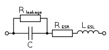
Niobium electrolytic capacitors as discrete components are not ideal capacitors, they have losses and parasitic inductive parts. All properties can be defined and specified by a series equivalent circuit composed out of an idealized capacitance and additional electrical components which model all losses and inductive parameters of a capacitor. In this series-equivalent circuit the electrical characteristics are defined by:
- C, the capacitance of the capacitor
- Rleak, the resistance representing the leakage current of the capacitor
- RESR, the equivalent series resistance which summarizes all ohmic losses of the capacitor, usually abbreviated as "ESR"
- LESL, the equivalent series inductance which is the effective self-inductance of the capacitor, usually abbreviated as "ESL".
Using a series equivalent circuit instead of a parallel equivalent circuit is specified by IEC/EN 60384-1.
Capacitance standard values and tolerances
The electrical characteristics of niobium electrolytic capacitors depend on structure of the anode and the type of electrolyte. The capacitance value of the capacitor depends on measuring frequency and temperature. The rated capacitance value or nominal value is specified in the data sheets of the manufacturers and is symbolized CR CN. The standardized measuring condition for electrolytic capacitors an AC measuring method with a frequency of 100/120 Hz. The AC measuring voltage shall not exceed 0,5 V AC-RMS.
The percentage of allowed deviation of the measured capacitance from the rated value is called capacitance tolerance. Electrolytic capacitors are available in different tolerance series, whose values are specified in the E series specified in IEC 60063. For abbreviated marking in tight spaces, a letter code for each tolerance is specified in IEC 60062.
- rated capacitance, E3 series, tolerance ±20%, letter code "M"
- rated capacitance, E6 series, tolerance ±20%, letter code "M"
- rated capacitance, E12 series, tolerance ±10%, letter code "K"
Rated and category voltage

Referring to IEC/EN 60384-1 standard the allowed operating voltage for niobium capacitors is called "rated voltage UR " or "nominal voltage UN". The rated voltage UR is the maximum DC voltage or peak pulse voltage that may be applied continuously at any temperature within the rated temperature range TR (IEC/EN 60384-1).
The voltage proof of electrolytic capacitors decreases with increasing temperature. For some applications it is important to use a higher temperature range. Lowering the voltage applied at a higher temperature maintains safety margins. For some capacitor types therefore the IEC standard specify a "temperature derated voltage" for a higher temperature, the "category voltage UC". The category voltage is the maximum DC voltage or peak pulse voltage that may be applied continuously to a capacitor at any temperature within the category temperature range TC. The relation between both voltages and temperatures is given in the picture right.
Lower voltage applied may have positive influences for tantalum electrolytic capacitors. Lowering the voltage applied increases the reliability and reduce the expected failure rate.[14]
Applying a higher voltage than specified may destroy electrolytic capacitors.
Surge Voltage
The surge voltage indicates the maximum peak voltage value that may be applied to electrolytic capacitors during their application for a limited number of cycles. The surge voltage is standardized in IEC/EN 60384-1. For niobium electrolytic capacitors the surge voltage shall be not higher than round 1.3 times of the rated voltage, rounded off to the nearest volt. The surge voltage applied to niobium capacitors may influence the capacitors failure rate.
Reverse voltage
Like other electrolytic capacitors, niobium electrolytic capacitors are polarized and require the anode electrode voltage to be positive relative to the cathode voltage.
Impedance, ESR and dissipation factor, ripple current , leakage current
General information to impedance, ESR, dissipation factor tan δ, ripple current, and leakage current see electrolytic capacitor
Reliability and life time
For general information on reliability and failure rate see electrolytic capacitor.
The life time, service life, load life or useful life of electrolytic capacitors is a special characteristic of non-solid electrolytic capacitors, especially non-solid aluminum electrolytic capacitors which liquid electrolyte can evaporate over the time leading to wear-out failures. Solid niobium capacitors with manganese dioxide electrolyte have no wear-out mechanism so the constant failure rate lasts up to the point all capacitors have failed. They don't have a life time specification like non-solid aluminum electrolytic capacitors.
However, solid polymer niobium electrolytic capacitors do have a life time specification. The polymer electrolyte deteriorates by a thermal degradation mechanism of the conductive polymer. The electrical conductivity decreases, as a function of time, in agreement with a granular structure, in which aging is due to the shrinking of the conductive polymer grains.[15] The life time of polymer electrolytic capacitors is specified in similar terms like non-solid e-caps but its life time calculation follows other rules leading to much longer operational life times.[16][17][18]
Failure modes, self-healing mechanism and application rules
The different types of electrolytic capacitors show different behaviors in long-term stability, inherent failure modes and their self-healing mechanisms. Application rules for types with an inherent failure mode are specified to ensure capacitors high reliability and long life.
| Type of electrolytic capacitors | Long-term electrical behavior | Failure modes | Self-healing mechanism | Application rules |
|---|---|---|---|---|
| Tantalum e-caps solid MnO2 electrolyte | stable | Field crystallization[19][20] | Thermally induced insulating of faults in the dielectric by decomposition of the electrolyte MnO2 into insulating Mn2O3 if current availability is limited | Voltage derating 50% Series resistance 3 Ω/V[21][22] |
| Tantalum e-caps solid polymer electrolyte | Deterioration of conductivity, ESR increases | Field crystallization[19][20] | Insulating of faults in the dielectric by oxidation or evaporation of the polymer electrolyte | Voltage derating 20%[21][22] |
| Niobium e-caps, solid MnO2 electrolyte | stable | no unique determinable | Thermally induced insulation of faults in the dielectric by reduction of Nb2O5 into insulating NbO2 | niobium anode: voltage derating 50% niobium oxide anode: voltage derating 20%[21][22] |

A rare failure in solid electrolytic capacitors is breakdown of the dielectric caused by faults or impurities. In niobium electrolytic capacitors the dielectric is niobium pentoxide (Nb2O5). Besides this pentoxide there is an additional niobium suboxide, niobium dioxide (NbO2). The NbO2 is a semi-conducting material with a higher conductivity than Nb2O5 but much lower than a short. In case of faults or impurities in the dielectric which evokes a partial dielectric breakdown the conducting channel would be effectively isolated by reduction of Nb2O5 into high ohmic NbO2 if energy is limited.
As more energy is applied to a faulty solid niobium eventually either the high ohmic NbO2 channel or the Nb2O5 dielectric breaks down and the capacitor exhibits a thermal runaway failure. In comparison to solid tantalum capacitors the thermal runaway of niobium anodes will occur at about three times higher power than of tantalum anodes. This gives a significant reduction (95%) of the ignition failure mode compared to solid tantalum capacitors.
The dielectric layer Nb2O5 of solid niobium electrolytic capacitors has a lower breakdown voltage proof than Ta2O5 in tantalum capacitors and therefore grows thicker per applied volt and so operates at lower field strength for a given voltage rating with the lower electrical stress the dielectric. In combination with niobium oxide anodes, which are more stable against oxygen diffusion that results in lower voltage derating rules compared with passivated niobium or tantalum anodes.[6]
Additional information
Capacitor symbols
Electrolytic capacitor symbols
| Electrolytic capacitor | Electrolytic capacitor | Electrolytic capacitor |
Polarity marking
Niobium capacitors are in general polarized components, with distinctly marked positive terminals. When subjected to reversed polarity (even briefly), the capacitor depolarizes and the dielectric oxide layer breaks down, which can cause it to fail even when later operated with correct polarity. If the failure is a short circuit (the most common occurrence), and current is not limited to a safe value, catastrophic thermal runaway may occur.
Standardization
The standardization for all electrical, electronic components and related technologies follows the rules given by the International Electrotechnical Commission (IEC),[23] a non-profit, non-governmental international standards organization.[24][25] The definition of the characteristics and the procedure of the test methods for capacitors for use in electronic equipment are set out in the generic specification:
- IEC 60384-1, Fixed capacitors for use in electronic equipment - Part 1: Generic specification
Until now (2014) no IEC detail specification for niobium electrolytic capacitors is available.
For electronics manufacturers in the United States the EIA publish a standard for niobium and tantalum chip capacitors:
- EIA-717-A Surface Mount Niobium and Tantalum Capacitor Qualification Specification
Features
- Niobium capacitors serve as a replacement for tantalum capacitors
- Niobium capacitors are available in SMD style, that makes them suitable for all portable electronic systems with flat design
- Niobium capacitors have no inrush current limitation
- Niobium capacitors are available with solid electrolyte for low ESR applications and stable electrical parameters
- Niobium capacitors have a limited number of manufacturers (AVX and Vishay)[26]
See also
- Types of capacitor
Bibliography
- R. P. Deshpande, Capacitors: Technology and Trends, ISBN 1259007316
- D. Bach, Dissertation, 05.06.2009, Universität Karlsruhe (TH), EELS investigations of stoichiometric niobium oxides and niobium-based capacitors
- Ch. Schnitter: The taming of niobium. In: Bayer research, Bayer AG, 2004 (Version vom 11. February 2007 im Internet Archive),
- Niobium Powder for Electrolytic Capacitor, JFE TECHNICAL REPORT No. 6 (Oct. 2005) PDF
- Introduction to capacitors
References
- Tantalum-Niobium International Study Center, Tantalum and Niobium - Early History and Applications for Niobium Archived 2016-02-13 at the Wayback Machine
- T. Zednicek, S. Sita, C. McCracken, W. A. Millman, J. Gill, AVX, Niobium Oxide Technology Roadmap, CARTS 2002 PDF Archived 2014-02-24 at the Wayback Machine
- Ch. Schnitter, A. Michaelis, U. Merker, H.C. Starck, Bayer, New Niobium Based Materials for Solid Electrolyte Capacitors, Carts 2002
- J. Moore, Kemet, Nb capacitors compared to Ta capacitors a less costly alternative PDF
- Niobium Powder for Electrolytic Capacitor, JFE TECHNICAL REPORT No. 6 (Oct. 2005) PDF
- T. Kárník, AVX, NIOBIUM OXIDE FOR CAPACITOR MANUFACTURING , METAL 2008, 13. –15. 5. 2008, PDF
- Y. Pozdeev-Freeman, P. Maden, Vishay, Solid-Electrolyte Niobium Capacitors Exhibit Similar Performance to Tantalum, Feb 1, 2002,
- Rutronik, Tantalum & Niobium Capacitors, Technical Standards and Benefits PDF
- Charles Pollack: D.R.P. 92564, filed 14. January 1896, granted 19. May 1897 D.R.P. 92564
- D. F. Tailor, Tantalum and Tantalum Compounds, Fansteel Inc., Encyclopedia of Chemical Technology, Vol. 19, 2nd ed. 1969 John Wiley & sons, Inc.
- R. L. Taylor and H. E. Haring, "A metal semi-conductor capacitor," J. Electrochem. Soc., vol. 103, p. 611, November, 1956.
- E. K. Reed, Jet Propulsion Laboratory, Characterization of Tantalum Polymer Capacitors, NEPP Task 1.21.5, Phase 1, FY05]
- D. A. McLean, F. S. Power, Proc. Inst. Radio Engrs. 44 (1956) 872
- Ch. Reynolds, AVX, Technical Information, Reliability Management of Tantalum Capacitors, PDF Archived 2013-08-06 at the Wayback Machine
- E. Vitoratos, S. Sakkopoulos, E. Dalas, N. Paliatsas, D. Karageorgopoulos, F. Petraki, S. Kennou, S.A. Choulis, Thermal degradation mechanisms of PEDOT:PSS, Organic Electronics, Volume 10, Issue 1, February 2009, Pages 61–66,
- Nichicon, Technical Guide, Calculation Formula of Lifetime PDF
- Estimating of Lifetime FUJITSU MEDIA DEVICES LIMITED PDF Archived 2013-12-24 at the Wayback Machine
- NIC Technical Guide, Calculation Formula of Lifetime Archived 2013-09-15 at the Wayback Machine
- T.Zednicek, AVX, A Study of Field Crystallization in Tantalum Capacitors and its effect on DCL and Reliability,
- VISHAY, DC LEAKAGE FAILURE MODE, PDF
- J.Gill, T. Zednicek, AVX, VOLTAGE DERATING RULES FOR SOLID TANTALUM AND NIOBIUM CAPACITORS, "Archived copy" (PDF). Archived from the original (PDF) on 2013-08-06. Retrieved 2015-01-02.CS1 maint: archived copy as title (link)
- R. Faltus, AVX, Advanced capacitors ensure long-term control-circuit stability, 7/2/2012, EDT
- IEC Homepage
- IEC Webstore
- IEC/EN/DIN Standards, Beuth-Verlag
- G. Roos, Digi-Key, Niobium Capacitors Slow to Take Hold, 2012-11-20