Mach–Zehnder interferometer
In physics, the Mach–Zehnder interferometer is a device used to determine the relative phase shift variations between two collimated beams derived by splitting light from a single source. The interferometer has been used, among other things, to measure phase shifts between the two beams caused by a sample or a change in length of one of the paths. The apparatus is named after the physicists Ludwig Mach (the son of Ernst Mach) and Ludwig Zehnder; Zehnder's proposal in an 1891 article[1] was refined by Mach in an 1892 article.[2]

Introduction
The Mach–Zehnder check interferometer is a highly configurable instrument. In contrast to the well-known Michelson interferometer, each of the well-separated light paths is traversed only once.
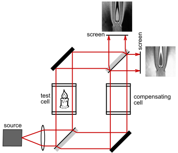
If the source has a low coherence length then great care must be taken to equalize the two optical paths. White light in particular requires the optical paths to be simultaneously equalized over all wavelengths, or no fringes will be visible. As seen in Fig. 1, a compensating cell made of the same type of glass as the test cell (so as to have equal optical dispersion) would be placed in the path of the reference beam to match the test cell. Note also the precise orientation of the beam splitters. The reflecting surfaces of the beam splitters would be oriented so that the test and reference beams pass through an equal amount of glass. In this orientation, the test and reference beams each experience two front-surface reflections, resulting in the same number of phase inversions. The result is that light travels through an equal optical path length in both the test and reference beams leading to constructive interference.[3][4]
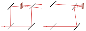
Collimated sources result in a nonlocalized fringe pattern. Localized fringes result when an extended source is used. In Fig. 2, we see that the fringes can be adjusted so that they are localized in any desired plane.[5]:18 In most cases, the fringes would be adjusted to lie in the same plane as the test object, so that fringes and test object can be photographed together.
The Mach–Zehnder interferometer's relatively large and freely accessible working space, and its flexibility in locating the fringes has made it the interferometer of choice for visualizing flow in wind tunnels[6][7] and for flow visualization studies in general. It is frequently used in the fields of aerodynamics, plasma physics and heat transfer to measure pressure, density, and temperature changes in gases.[5]:18,93–95
Mach–Zehnder interferometers are used in electro-optic modulators, electronic devices used in various fiber-optic communication applications. Mach–Zehnder modulators are incorporated in monolithic integrated circuits and offer well-behaved, high-bandwidth electro-optic amplitude and phase responses over a multiple-gigahertz frequency range.
Mach–Zehnder interferometers are also used to study one of the most counterintuitive predictions of quantum mechanics, the phenomenon known as quantum entanglement.[8][9]
The possibility to easily control the features of the light in the reference channel without disturbing the light in the object channel popularized the Mach–Zehnder configuration in holographic interferometry. In particular, optical heterodyne detection with an off-axis, frequency-shifted reference beam ensures good experimental conditions for shot-noise limited holography with video-rate cameras,[10] vibrometry,[11] and laser Doppler imaging of blood flow.[12]
How it works
Set-up
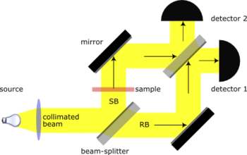
A collimated beam is split by a half-silvered mirror. The two resulting beams (the "sample beam" and the "reference beam") are each reflected by a mirror. The two beams then pass a second half-silvered mirror and enter two detectors.
Properties
The Fresnel equations for reflection and transmission of a wave at a dielectric imply that there is a phase change for a reflection, when a wave propagating in a lower-refractive index medium reflects from a higher-refractive index medium, but not in the opposite case.
A 180° phase shift occurs upon reflection from the front of a mirror, since the medium behind the mirror (glass) has a higher refractive index than the medium the light is traveling in (air). No phase shift accompanies a rear-surface reflection, since the medium behind the mirror (air) has a lower refractive index than the medium the light is traveling in (glass).
The speed of light is lower in media with an index of refraction greater than that of a vacuum, which is 1. Specifically, its speed is: v = c/n, where c is the speed of light in vacuum, and n is the index of refraction. This causes a phase shift increase proportional to (n − 1) × length traveled. If k is the constant phase shift incurred by passing through a glass plate on which a mirror resides, a total of 2k phase shift occurs when reflecting from the rear of a mirror. This is because light traveling toward the rear of a mirror will enter the glass plate, incurring k phase shift, and then reflect from the mirror with no additional phase shift, since only air is now behind the mirror, and travel again back through the glass plate, incurring an additional k phase shift.
The rule about phase shifts applies to beamsplitters constructed with a dielectric coating and must be modified if a metallic coating is used or when different polarizations are taken into account. Also, in real interferometers, the thicknesses of the beamsplitters may differ, and the path lengths are not necessarily equal. Regardless, in the absence of absorption, conservation of energy guarantees that the two paths must differ by a half-wavelength phase shift. Also note that beamsplitters that are not 50/50 are frequently employed to improve the interferometer's performance in certain types of measurement.[3]
Observing the effect of a sample
In Fig. 3, in the absence of a sample, both the sample beam (SB) and the reference beam (RB) will arrive in phase at detector 1, yielding constructive interference. Both SB and RB will have undergone a phase shift of (1 × wavelength + k) due to two front-surface reflections and one transmission through a glass plate.
At detector 2, in the absence of a sample, the sample beam and reference beam will arrive with a phase difference of half a wavelength, yielding complete destructive interference. The RB arriving at detector 2 will have undergone a phase shift of (0.5 × wavelength + 2k) due to one front-surface reflection and two transmissions. The SB arriving at detector 2 will have undergone a (1 × wavelength + 2k) phase shift due to two front-surface reflections, one rear-surface reflection and two transmissions. Therefore, when there is no sample, only detector 1 receives light.
If a sample is placed in the path of the sample beam, the intensities of the beams entering the two detectors will change, allowing the calculation of the phase shift caused by the sample.
Applications
The versatility of the Mach–Zehnder configuration has led to its being used in a wide range of fundamental research topics in quantum mechanics, including studies on counterfactual definiteness, quantum entanglement, quantum computation, quantum cryptography, quantum logic, Elitzur–Vaidman bomb tester, the quantum eraser experiment, the quantum Zeno effect, and neutron diffraction. In optical telecommunications it is used as an electro-optic modulator for phase and amplitude modulation of light.
See also
- Interferometry
- List of types of interferometers
- Fizeau interferometer
- Fabry–Pérot interferometer
- Jamin interferometer
- Ramsey–Bordé interferometer
Related forms of interferometer
- Classical interference microscopy
- Dual polarisation interferometry
Other flow visualisation techniques
References
- Zehnder, Ludwig (1891). "Ein neuer Interferenzrefraktor". Zeitschrift für Instrumentenkunde. 11: 275–285.
- Mach, Ludwig (1892). "Ueber einen Interferenzrefraktor". Zeitschrift für Instrumentenkunde. 12: 89–93.
- Zetie, K. P.; Adams, S. F.; Tocknell, R. M. "How does a Mach–Zehnder interferometer work?" (PDF). Physics Department, Westminster School, London. Retrieved 8 April 2012.
- Ashkenas, Harry I. (1950). The design and construction of a Mach–Zehnder interferometer for use with the GALCIT Transonic Wind Tunnel. Engineer's thesis. California Institute of Technology.
- Hariharan, P. (2007). Basics of Interferometry. Elsevier Inc. ISBN 978-0-12-373589-8.
- Chevalerias, R.; Latron, Y.; Veret, C. (1957). "Methods of Interferometry Applied to the Visualization of Flows in Wind Tunnels". Journal of the Optical Society of America. 47 (8): 703. doi:10.1364/JOSA.47.000703.
- Ristić, Slavica. "Flow visualization techniques in wind tunnels – optical methods (Part II)" (PDF). Military Technical Institute, Serbia. Retrieved 6 April 2012.
- Paris, M. G. A. (1999). "Entanglement and visibility at the output of a Mach–Zehnder interferometer" (PDF). Physical Review A. 59 (2): 1615–1621. arXiv:quant-ph/9811078. Bibcode:1999PhRvA..59.1615P. doi:10.1103/PhysRevA.59.1615. Archived from the original (PDF) on 10 September 2016. Retrieved 2 April 2012.
- Haack, G. R.; Förster, H.; Büttiker, M. (2010). "Parity detection and entanglement with a Mach-Zehnder interferometer". Physical Review B. 82 (15): 155303. arXiv:1005.3976. Bibcode:2010PhRvB..82o5303H. doi:10.1103/PhysRevB.82.155303.
- Michel Gross; Michael Atlan (2007). "Digital holography with ultimate sensitivity". Optics Letters. 32 (8): 909–911. arXiv:0803.3076. Bibcode:2007OptL...32..909G. doi:10.1364/OL.32.000909.
- Francois Bruno; Jérôme Laurent; Daniel Royer; Michael Atlan (2014). "Holographic imaging of surface acoustic waves". Applied Physics Letters. 104 (1): 083504. arXiv:1401.5344. Bibcode:2014ApPhL.104a3504Y. doi:10.1063/1.4861116.
- Caroline Magnain; Amandine Castel; Tanguy Boucneau; Manuel Simonutti; Isabelle Ferezou; Armelle Rancillac; Tania Vitalis; José-Alain Sahel; Michel Paques; Michael Atlan (2014). "Holographic imaging of surface acoustic waves". Journal of the Optical Society of America A. 31 (12): 2723–2735. arXiv:1412.0580. Bibcode:2014JOSAA..31.2723M. doi:10.1364/JOSAA.31.002723. PMID 25606762.