Kelvin probe force microscope
Kelvin probe force microscopy (KPFM), also known as surface potential microscopy, is a noncontact variant of atomic force microscopy (AFM).[1][2][3] With KPFM, the work function of surfaces can be observed at atomic or molecular scales. The work function relates to many surface phenomena, including catalytic activity, reconstruction of surfaces, doping and band-bending of semiconductors, charge trapping in dielectrics and corrosion. The map of the work function produced by KPFM gives information about the composition and electronic state of the local structures on the surface of a solid.
Working principle
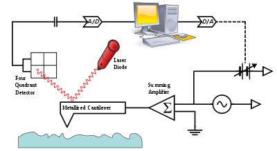
KPFM is a scanning probe method where the potential offset between a probe tip and a surface can be measured using the same principle as a macroscopic scanning Kelvin probe. The cantilever in the AFM is a reference electrode that forms a capacitor with the surface, over which it is scanned laterally at a constant separation. The cantilever is not piezoelectrically driven at its mechanical resonance frequency ω0 as in normal AFM although an alternating current (AC) voltage is applied at this frequency.
When there is a direct-current (DC) potential difference between the tip and the surface, the AC+DC voltage offset will cause the cantilever to vibrate. The origin of the force can be understood by considering that the energy of the capacitor formed by the cantilever and the surface is

plus terms at DC. Only the cross-term proportional to the VDC·VAC product is at the resonance frequency ω0. The resulting vibration of the cantilever is detected using usual scanned-probe microscopy methods (typically involving a diode laser and a four-quadrant detector). A null circuit is used to drive the DC potential of the tip to a value which minimizes the vibration. A map of this nulling DC potential versus the lateral position coordinate therefore produces an image of the work function of the surface.
A related technique, electrostatic force microscopy (EFM), directly measures the force produced on a charged tip by the electric field emanating from the surface. EFM operates much like magnetic force microscopy in that the frequency shift or amplitude change of the cantilever oscillation is used to detect the electric field. However, EFM is much more sensitive to topographic artifacts than KPFM. Both EFM and KPFM require the use of conductive cantilevers, typically metal-coated silicon or silicon nitride.
Work function
The Kelvin probe force microscope or Kelvin force microscope (KFM) is based on an AFM set-up and the determination of the work function is based on the measurement of the electrostatic forces between the small AFM tip and the sample. The conducting tip and the sample are characterized by (in general) different work functions, which represent the difference between the Fermi level and the vacuum level for each material. If both elements were brought in contact, a net electric current would flow between them until the Fermi levels were aligned. The difference between the work functions is called the contact potential difference and is denoted generally with VCPD. An electrostatic force exists between tip and sample, because of the electric field between them. For the measurement a voltage is applied between tip and sample, consisting of a DC-bias VDC and an AC-voltage VAC sin(ωt) of frequency ω.

Tuning the AC-frequency to the resonant frequency of the AFM cantilever results in an improved sensitivity. The electrostatic force in a capacitor may be found by differentiating the energy function with respect to the separation of the elements and can be written as

where C is the capacitance, z is the separation, and V is the voltage, each between tip and surface. Substituting the previous formula for voltage (V) shows that the electrostatic force can be split up into three contributions, as the total electrostatic force F acting on the tip then has spectral components at the frequencies ω and 2ω.

The DC component, FDC, contributes to the topographical signal, the term Fω at the characteristic frequency ω is used to measure the contact potential and the contribution F2ω can be used for capacitance microscopy.


Contact potential measurements
For contact potential measurements a lock-in amplifier is used to detect the cantilever oscillation at ω. During the scan VDC will be adjusted so that the electrostatic forces between the tip and the sample become zero and thus the response at the frequency ω becomes zero. Since the electrostatic force at ω depends on VDC − VCPD, the value of VDC that minimizes the ω-term corresponds to the contact potential. Absolute values of the sample work function can be obtained if the tip is first calibrated against a reference sample of known work function.[4] Apart from this, one can use the normal topographic scan methods at the resonance frequency ω independently of the above. Thus, in one scan, the topography and the contact potential of the sample are determined simultaneously. This can be done in (at least) two different ways: 1) The topography is captured in AC mode which means that the cantilever is driven by a piezo at its resonant frequency. Simultaneously the AC voltage for the KPFM measurement is applied at a frequency slightly lower than the resonant frequency of the cantilever. In this measurement mode the topography and the contact potential difference are captured at the same time and this mode is often called single-pass. 2) One line of the topography is captured either in contact or AC mode and is stored internally. Then, this line is scanned again, while the cantilever remains on a defined distance to the sample without a mechanically driven oscillation but the AC voltage of the KPFM measurement is applied and the contact potential is captured as explained above. It is important to note that the cantilever tip must not be too close to the sample in order to allow good oscillation with applied AC voltage. Therefore, KPFM can be performed simultaneously during AC topography measurements but not during contact topography measurements.
References
- M. Nonnenmacher; M. P. O'Boyle; H. K. Wickramasinghe (1991). "Kelvin probe force microscopy" (PDF). Appl. Phys. Lett. 58 (25): 2921. Bibcode:1991ApPhL..58.2921N. doi:10.1063/1.105227. Archived from the original (free-download pdf) on 2009-09-20.
- Fujihira, Masamichi (1999). "KELVIN PROBE FORCE MICROSCOPY OF MOLECULAR SURFACES". Annual Review of Materials Science. 29 (1): 353–380. Bibcode:1999AnRMS..29..353F. doi:10.1146/annurev.matsci.29.1.353. ISSN 0084-6600.
- Melitz, Wilhelm; Shen, Jian; Kummel, Andrew C.; Lee, Sangyeob (2011). "Kelvin probe force microscopy and its application". Surface Science Reports. 66 (1): 1–27. Bibcode:2011SurSR..66....1M. doi:10.1016/j.surfrep.2010.10.001. ISSN 0167-5729.
- Fernández Garrillo, P. A.; Grévin, B.; Chevalier, N.; Borowik, Ł. (2018). "Calibrated work function mapping by Kelvin probe force microscopy". Review of Scientific Instruments. 89 (4): 043702. doi:10.1063/1.5007619.
External links
- Masaki Takihara (9 December 2008). "Kelvin probe force microscopy". Takahashi Lab., Institute of Industrial Science, University of Tokyo. Archived from the original on 29 October 2012. Retrieved 29 February 2012. – Full description of the principles with good illustrations to aid comprehension
- Transport measurements by Scanning Probe Microscopy
- Introduction to Kelvin Probe Force Microscopy (KPFM)
- Dynamic Kelvin Probe Force Microscopy
- Kelvin Probe Force Microscopy of Lateral Devices
- Kelvin Probe Force Microscopy in Liquids
- Current-voltage Measurements in Scanning Probe Microscopy
- Dynamic IV measurements in SPM
| Common | 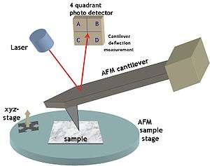 Typical atomic force microscopy set-up | |
|---|---|---|
| Other |
| |
| Applications | ||
| See also | ||