In-phase and quadrature components
In electrical engineering, a sinusoid with angle modulation can be decomposed into, or synthesized from, two amplitude-modulated sinusoids that are offset in phase by one-quarter cycle (π/2 radians). All three functions have the same center frequency. The amplitude modulated sinusoids are known as the in-phase and quadrature components.[1] In some contexts it is more convenient to refer to only the amplitude modulation (baseband) itself by those terms.[2]


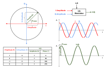
The phase modulation (φ(t), not shown) is a non-linearly increasing function from 0 to π/2 over the interval 0 < t < 16. The two amplitude-modulated components are known as the in-phase component (I, thin blue, decreasing) and the quadrature component (Q, thin red, increasing).
Concept
In vector analysis, a vector with polar coordinates A,φ and Cartesian coordinates x = A cos(φ), y = A sin(φ), can be represented as the sum of orthogonal components: [x,0] + [0,y]. Similarly in trigonometry, the angle sum identity expresses:
- sin(x + φ)=sin(x) cos(φ) + sin(x + π/2) sin(φ).
And in functional analysis, when x is a linear function of some variable, such as time, these components are sinusoids, and they are orthogonal functions. A phase-shift of x → x + π/2 changes the identity to:
- cos(x + φ) = cos(x) cos(φ) + cos(x + π/2) sin(φ),
in which case cos(x) cos(φ) is the in-phase component. In both conventions cos(φ) is the in-phase amplitude modulation, which explains why some authors refer to it as the actual in-phase component.
Alternating current (AC) circuits
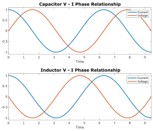
The term alternating current applies to a voltage vs. time function that is sinusoidal with a frequency f. When it is applied to a typical (linear) circuit or device, it causes a current that is also sinusoidal. In general there is a constant phase difference, φ, between any two sinusoids. The input sinusoidal voltage is usually defined to have zero phase, meaning that it is arbitrarily chosen as a convenient time reference. So the phase difference is attributed to the current function, e.g. sin(2πft + φ), whose orthogonal components are sin(2πft) cos(φ) and sin(2πft + π/2) sin(φ), as we have seen. When φ happens to be such that the in-phase component is zero, the current and voltage sinusoids are said to be in quadrature, which means they are orthogonal to each other. In that case, no electrical power is consumed. Rather it is temporarily stored by the device and given back, once every 1⁄f seconds. Note that the term in quadrature only implies that two sinusoids are orthogonal, not that they are components of another sinusoid.
Narrowband signal model
In an angle modulation application, with carrier frequency f, φ is also a time-variant function, giving:

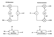
When all three terms above are multiplied by an optional amplitude function, A(t) > 0, the left-hand side of the equality is known as the amplitude/phase form, and the right-hand side is the quadrature-carrier or IQ form. Because of the modulation, the components are no longer completely orthogonal functions. But when A(t) and φ(t) are slowly varying functions compared to 2πft, the assumption of orthogonality is a common one.[upper-alpha 1] Authors often call it a narrowband assumption, or a narrowband signal model.[3][4]
IQ phase convention
The terms I-component and Q-component are common ways of referring to the in-phase and quadrature signals. Both signals comprise a high-frequency sinusoid (or carrier) that is amplitude-modulated by a relatively low-frequency function, usually conveying some sort of information. The two carriers are orthogonal, with I lagging Q by ¼ cycle, or equivalently leading Q by ¾ cycle. The physical distinction can also be characterized in terms of :

- : The composite signal reduces to just the I-component, which accounts for the term in-phase.
- : The composite signal reduces to just the Q-component.
- : The amplitude modulations are orthogonal sinusoids, I leading Q by ¼ cycle.
- : The amplitude modulations are orthogonal sinusoids, Q leading I by ¼ cycle.


See also
Notes
- Orthogonality is important in many applications, including demodulation, direction-finding, and bandpass sampling.
References
- Gast, Matthew (2005-05-02). 802.11 Wireless Networks: The Definitive Guide. 1 (2 ed.). Sebastopol,CA: O'Reilly Media. p. 284. ISBN 0596100523.
- Franks, L.E. (September 1969). Signal Theory. Information theory. Englewood Cliffs, NJ: Prentice Hall. p. 82. ISBN 0138100772.
- Wade, Graham (1994-09-30). Signal Coding and Processing. 1 (2 ed.). Cambridge University Press. p. 10. ISBN 0521412307.
- Naidu, Prabhakar S. (November 2003). Modern Digital Signal Processing: An Introduction. Pangbourne RG8 8UT, UK: Alpha Science Intl Ltd. pp. 29–31. ISBN 1842651331.CS1 maint: location (link)
Further reading
- Steinmetz, Charles Proteus (2003-02-20). Lectures on Electrical Engineering. 3 (1 ed.). Mineola,NY: Dover Publications. ISBN 0486495388.
- Steinmetz, Charles Proteus (1917). Theory and Calculations of Electrical Apparatus 6 (1 ed.). New York: McGraw-Hill Book Company. B004G3ZGTM.