Friction welding
Friction welding (FRW) is a solid-state welding process that generates heat through mechanical friction between workpieces in relative motion to one another, with the addition of a lateral force called "upset" to plastically displace and fuse the materials. Because no melting occurs, friction welding is not a fusion welding process in the traditional sense, but more of a forge welding technique. Friction welding is used with metals and thermoplastics in a wide variety of aviation and automotive applications.
Advantages
The combination of fast joining times (on the order of a few seconds) and direct heat input at the weld interface yields relatively small heat-affected zones. Friction welding techniques are generally melt-free, which mitigates grain growth in engineered materials such as high-strength heat-treated steels. Another advantage is that the motion tends to clean the surface between the materials being welded, which means they can be joined with less preparation. During the welding process, depending on the method being used, small pieces of the plastic or metal will be forced out of the working mass (flash). It is believed that the flash carries away debris and dirt.
Another advantage of friction welding is that it allows dissimilar materials to be joined. This is particularly useful in aerospace, where it is used to join lightweight aluminum stock to high-strength steels. Normally the wide difference in melting points of the two materials would make it impossible to weld using traditional techniques and would require some sort of mechanical connection. Friction welding provides a full-strength bond with no additional weight. Other common uses for these sorts of bi-metal joins is in the nuclear industry, where copper-steel joints are common in the reactor cooling systems; and in the transport of cryogenic fluids, where friction welding has been used to join aluminum alloys to stainless steels and high-nickel-alloy materials for cryogenic-fluid piping and containment vessels. Friction welding is also used with thermoplastics, which act in a fashion analogous to metals under heat and pressure. The heat and pressure used on these materials is much lower than metals, but the technique can be used to join metals to plastics with the metal interface being machined. For instance, the technique can be used to join eyeglass frames to the pins in their hinges. The lower energies and pressures used allows for a wider variety of techniques to be used.
Sintered materials such as Al, Cu, Ti, Mg alloys, heat resistant Ni and Co alloys and refractory materials such as Ta and Mo alloys can successfully be joined by friction welding.[1]
Disadvantages
- Working piece dimensional limitations
- FRW is restricted mostly for round bars with similar cross-section; pieces of other forms are still possible to wield but it is much harder
- Need to fix the workpiece
- Joint design limitations
- Impossibility to forge workpieces consisting of non-forgeable materials; difficulties associated with experimental materials
- Cost of FRW equipment, high capital costs[1]
History
Friction welding was first developed in the Soviet Union, with first experiments taking place in 1956. The American companies Caterpillar, Rockwell International, and American Manufacturing Foundry all developed machines for this process. Patents were also issued throughout Europe and the former Soviet Union.
Metal techniques
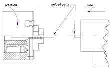
Rotary friction welding
Rotary friction welding (RFW), for plastics also known as spin welding, uses machines that have two chucks for holding the materials to be welded, one of which is fixed and the other rotating.

In direct-drive friction welding (also called continuous drive friction welding) the drive motor and chuck are connected. The drive motor is continually driving the chuck during the heating stages. Usually, a clutch is used to disconnect the drive motor from the chuck, and a brake is then used to stop the chuck.
In inertia friction welding the drive motor is disengaged, and the workpieces are forced together by a friction welding force. The kinetic energy stored in the rotating flywheel is dissipated as heat at the weld interface as the flywheel speed decreases. Before welding, one of the workpieces is attached to the rotary chuck along with a flywheel of a given weight. The piece is then spun up to a high rate of rotation to store the required energy in the flywheel. Once spinning at the proper speed, the motor is removed and the pieces forced together under pressure. The force is kept on the pieces after the spinning stops to allow the weld to "set".[2]
Friction work is converted into rise of temperature in the welding zone area, and as a result of this the weld structure is changed. Individual thermomechanical zones can be described by citing an example article: R.McAndrew and others, "A literature review of Ti-6Al-4V linear friction welding", 2018.[3]
"Technically the WCZ and the TMAZ are both "thermo-mechanically affected zonez" but due to the vastly different microstructures they possess they are often considered separately. The WCZ experiences significant dynamic recrystallisation (DRX), the TMAZ does not. The material in HAZ is not deformed mechanically but is affected by the heat. The region from one TMAZ/HAZ boundary to the other is often referred to as the "TMAZ thickness" or the plastically affected zone (PAZ). For the remainder of this article this region will be referred to as the PAZ"[3]
The setting of the completely different parameters can obtain different weld for example the structure changes will not be the same width. It is possible to obtain a smaller heat-affected zone (HAZ) and a plastically affected zone (PAZ). The width of the weld is smaller. The results are for example not the same in welds made for the European Space Agency with a high turnover ω = 14000 rpm[4] or another example in Warsaw technical university 12000 rpm[5] and very short friction time only 60 ms[6] instead of using an standard parameters, in addition, in this case, ultra fine grain alloy was welded. Unfortunately the diameter of the workpiece can be a limitation to the use of high speeds of rotation.
There are many scientific articles describing the weld test, e.g. hardness, tensile tests. The weld structure can be examined by optical microscopy and scanning electron microscopy. The computer finite element method (FEM) is used to predict the shape of the flash and interface, not only for rotary friction welding (RFW), but also for friction stir welding (FSW), linear friction welding (LFW), FRIEX[7] and others. Temperature measurements are also carried out for scientific purposes. For example, temperature may reduce material properties, (e.g. dynamic recrystallization will occur).
During typical welding initially, the outer region heats up more, due to the higher linear velocity, next the heat spreads, the material is pushed outside, thus creating a flash.
Linear friction welding
Linear friction welding (LFW) is similar to spin welding, except that the moving chuck oscillates laterally instead of spinning. The speeds are much lower in general, which requires the pieces to be kept under pressure at all times. This also requires the parts to have a high shear strength. Linear friction welding requires more complex machinery than spin welding, but has the advantage that parts of any shape can be joined, as opposed to parts with a circular meeting point. Another advantage is that in many instances quality of joint is better than that obtained using rotating technique.
In June 2016, the following materials could be welded: commercially pure copper (C101) /commercially pure aluminium (AA1050) /aerospace grade aluminium alloy (AA6082) /microalloyed steel (proprietary) /nickel alloy (Inconel 718) to conform a single part with all five materials joined as a demonstrator using LFW. Previously, a world-record weld interface area of 13,000 mm2 was successfully welded using similar materials welding: aluminium, steel and aerospace-grade titanium.
The most important parameters in the LFW process are Friction Pressure, Forging Pressure, Burn-off, Frequency, Amplitude, Stick out and perhaps their respective ramps or variation against time. Friction Pressure is that developed between the parts to be welded during the oscillation period. Forging pressure is that maintained for a short period of time after the oscillation is stopped and is typically around 20% greater than the Friction Pressure. Burn-off is the change in length of the workpiece as its substance is turned into flash – material that escapes around the weld. Frequency and Amplitude describe the movement of the oscillator and hence of one of the parts to be welded. Stick out is the linear measurement of the amount of material that the parts have protruding from the tooling (oscillator and forging tooling).
Friction surfacing
Friction surfacing is a process derived from friction welding where a coating material is applied to a substrate. A rod composed of the coating material (called a mechtrode) is rotated under pressure, generating a plasticised layer in the rod at the interface with the substrate. By moving a substrate across the face of the rotating rod a plasticised layer is deposited, typically between 0.2–2.5 millimetres (0.0079–0.0984 in) thick with steels on steels, depending on mechtrode diameter and coating material. The process can be used with various metals, including aluminium onto aluminium.
Thermoplastic technique
Linear vibration welding
In linear vibration welding the materials are placed in contact and put under pressure. An external vibration force is then applied to slip the pieces relative to each other, perpendicular to the pressure being applied. The parts are vibrated through a relatively small displacement known as the amplitude, typically between 1.0 and 1.8 mm, for a frequency of vibration of 200 Hz (high frequency), or 2–4 mm at 100 Hz (low frequency), in the plane of the joint. This technique is widely used in the automotive industry, among others.[8] A minor modification is angular friction welding, which vibrates the materials by torquing them through a small angle.
Orbital friction welding
Orbital friction welding is similar to spin welding, but uses a more complex machine to produce an orbital motion in which the moving part rotates in a small circle, much smaller than the size of the joint as a whole.
Seizure resistance
Friction welding may unintentionally occur at sliding surfaces like bearings. This happens in particular if the lubricating oil film between sliding surfaces becomes thinner than the surface roughness, which may be due to low speed, low temperature, oil starvation, excessive clearance, low viscosity of the oil, high roughness of the surfaces, or a combination thereof.[9]
The seizure resistance is the ability of a material to resist friction welding. It is a fundamental property of bearing surfaces and in general of sliding surfaces under load.
See also
References
- UZKUT, Mehmet; ÜNLÜ, Bekir; YILMAZ, Selim; AKDAĞ, Mustafa. "Friction Welding And Its Applications In Today's World" (PDF). Celal Bayar Üniversitesi.
- video and schematic diagram
- McAndrew, Anthony R.; Colegrove, Paul A.; Bühr, Clement; Flipo, Bertrand C.D.; Vairis, Achilleas (2018-10-03). "A literature review of Ti-6Al-4V linear friction welding". Progress in Materials Science. 92: 225–257. doi:10.1016/j.pmatsci.2017.10.003. ISSN 0079-6425.
- M. Meisnar, S. Baker, J.M. Bennett, A. Bernad, A. Mostafa, S. Resch, N. Fernandes, A. Norman. (2017). "Microstructural characterization of rotary friction welded AA6082 and Ti-6Al-4V dissimilar joints". Materials & Design. (132,2017): 188–197. doi:10.1016/j.matdes.2017.07.004.CS1 maint: multiple names: authors list (link)
- B. Skowrońska, T. Chmielewski, W. Pachla, M. Kulczyk, J. Skiba, W. Presz (2019). "Friction Weldability of UFG 316L Stainless Steel" (PDF). Arch. Metall. Mater. 3, 64: 1051–1058 – via DOI: 10.24425/amm.2019.129494.CS1 maint: multiple names: authors list (link)
- Skowrońska, Beata; Siwek, Piotr; Chmielewski, Tomasz; Golański, Dariusz (2018-05-10). "Zgrzewanie tarciowe ultradrobnoziarnistej stali 316L". Przegląd Spawalnictwa - Welding Technology Review. 90 (5). doi:10.26628/ps.v90i5.917. ISSN 2449-7959.
- Pissanti, Daniela Ramminger; Scheid, Adriano; Kanan, Luis Fernando; Dalpiaz, Giovani; Kwietniewski, Carlos Eduardo Fortis (January 2019). "Pipeline girth friction welding of the UNS S32205 duplex stainless steel". Materials & Design. 162: 198–209. doi:10.1016/j.matdes.2018.11.046. ISSN 0264-1275.
- Plastics joining - Friction welding techniques
- Requirements to engine bearing materials, SubsTech