Circuit design
The process of circuit design can cover systems ranging from complex electronic systems all the way down to the individual transistors within an integrated circuit. For simple circuits the design process can often be done by one person without needing a planned or structured design process, but for more complex designs, teams of designers following a systematic approach with intelligently guided computer simulation are becoming increasingly common. In integrated circuit design automation, the term "circuit design" often refers to the step of the design cycle which outputs the schematics of the integrated circuit. Typically this is the step between logic design and physical design.[1]
Process
Formal circuit design usually involves a number of stages. Sometimes, a design specification is written after liaising with the customer. A technical proposal may be written to meet the requirements of the customer specification. The next stage involves synthesising on paper a schematic circuit diagram, an abstract electrical or electronic circuit that will meet the specifications. A calculation of the component values to meet the operating specifications under specified conditions should be made. Simulations may be performed to verify the correctness of the design.
A breadboard or other prototype version of the design for testing against specification may be built. It may involve the making of any alterations to the circuit to achieve compliance. A choice as to a method of construction as well as all the parts and materials to be used must be made. There is a presentation of component and layout information to draughtspersons, and layout and mechanical engineers, for prototype production. This is followed by the testing or type-testing a number of prototypes to ensure compliance with customer requirements. Usually there is a signing and approval of the final manufacturing drawings and there may be post-design services (obsolescence of components etc.).
Specification

The process of circuit design begins with the specification, which states the functionality that the finished design must provide, but does not indicate how it is to be achieved .[2] The initial specification is basically a technically detailed description of what the customer wants the finished circuit to achieve and can include a variety of electrical requirements, such as what signals the circuit will receive, what signals it must output, what power supplies are available and how much power it is permitted to consume. The specification can (and normally does) also set some of the physical parameters that the design must meet, such as size, weight, moisture resistance, temperature range, thermal output, vibration tolerance and acceleration tolerance.[3]
As the design process progresses the designer(s) will frequently return to the specification and alter it to take account of the progress of the design. This can involve tightening specifications that the customer has supplied, and adding tests that the circuit must pass in order to be accepted. These additional specifications will often be used in the verification of a design. Changes that conflict with or modify the customer's original specifications will almost always have to be approved by the customer before they can be acted upon.
Correctly identifying the customer needs can avoid a condition known as 'design creep' which occurs in the absence of realistic initial expectations, and later by failing to communicate fully with the client during the design process. It can be defined in terms of its results; "at one extreme is a circuit with more functionality than necessary, and at the other is a circuit having an incorrect functionality".[4] Nevertheless, some changes can be expected and it is good practice to keep options open for as long as possible because it's easier to remove spare elements from the circuit later on than it is to put them in.
Design
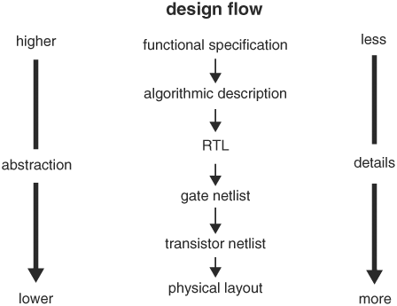
The design process involves moving from the specification at the start, to a plan that contains all the information needed to be physically constructed at the end, this normally happens by passing through a number of stages, although in very simple circuit it may be done in a single step.[5] The process normally begins with the conversion of the specification into a block diagram of the various functions that the circuit must perform, at this stage the contents of each block are not considered, only what each block must do, this is sometimes referred to as a "black box" design. This approach allows the possibly very complicated task to be broken into smaller tasks which may either by tackled in sequence or divided amongst members of a design team.
Each block is then considered in more detail, still at an abstract stage, but with a lot more focus on the details of the electrical functions to be provided. At this or later stages it is common to require a large amount of research or mathematical modeling into what is and is not feasible to achieve.[6] The results of this research may be fed back into earlier stages of the design process, for example if it turns out one of the blocks cannot be designed within the parameters set for it, it may be necessary to alter other blocks instead. At this point it is also common to start considering both how to demonstrate that the design does meet the specifications, and how it is to be tested ( which can include self diagnostic tools ).[7]

Finally the individual circuit components are chosen to carry out each function in the overall design, at this stage the physical layout and electrical connections of each component are also decided, this layout commonly taking the form of artwork for the production of a printed circuit board or Integrated circuit. This stage is typically extremely time-consuming because of the vast array of choices available. A practical constraint on the design at this stage is that of standardization, while a certain value of component may be calculated for use in some location in a circuit, if that value cannot be purchased from a supplier, then the problem has still not been solved. To avoid this a certain amount of 'catalog engineering' can be applied to solve the more mundane tasks within an overall design.
One area of rapid technology development is in the field of nanoelectronic circuit design.[8]
Costs
Everyone wants to know the cost of something when they are putting something together. Technical things such as circuit design can cost a lot of money. Circuits range in price from how complex things are to how simple things can be for circuits. Simple circuits don’t take as much work just cause the parallel to horizontal circuit make up isn’t to in depth as the complex circuit. To explain what a parallel and horizontal circuit is there are vertical and horizontal circuits within the circuit itself. These horizontal and vertical circuits will do different things and put off different amps and volts. Vertical and horizontal circuits do many different things. [9]
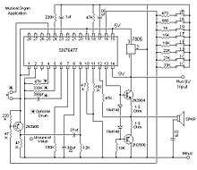
Here on the right you will see two images of complex circuits. The complex circuit is on the top and the simple is on the bottom. Everyone could probably imagine that the complex circuit will cost more than the simple circuit just cause of the labor and work taken to put together this circuit.
Verification and testing
Once a circuit has been designed, it must be both verified and tested. Verification is the process of going through each stage of a design and ensuring that it will do what the specification requires it to do. This is frequently a highly mathematical process and can involve large-scale computer simulations of the design. In any complicated design it is very likely that problems will be found at this stage and may involve a large amount of the design work be redone in order to fix them.
Testing is the real-world counterpart to verification, testing involves physically building at least a prototype of the design and then (in combination with the test procedures in the specification or added to it) checking the circuit really does do what it was designed to.
Prototyping
Prototyping is a big part of doing things that are very difficult. Circuit design forces you to keep going over things and fixing your mistakes. Circuit design is a very rigorous job to do and get done without making a mistake. Circuit designers must test many times to make sure their design works efficiently and most of all is safe for a consumer to buy and use.[10] Prototyping is a big part of any electrical work because it is very meticulous and to the point. Everyone could probably imagine the mistakes that will be made if there is no prototyping going on in the work being done. These workers are getting paid to not just make electrical circuits but to keep everyone who is buying these electrical circuits safe at home. The dangers of not prototyping and sending out a failed electrical circuit will include fires, hot wires, which in turn will make someone not know and cause them to either be burned and at the absolute worst severely hurt. [10]
Results
Every electrical circuit starts with a circuit board simulator of how the things will be put together at the end of the day and also show how the circuit will work virtually.[9] A blueprint is the drawing of the technical design and final product. After all this is done and you use the blueprint to put the circuit together you will get to the results of electrical circuits is quite memorable as the circuit will run anything from a vacuum to a big TV in a movie theater. All of these take a long time and a certain skill not everyone can acquire. The electrical circuit is something most things we need in our everyday lives.
Documentation
Any commercial design will normally also include an element of documentation, the precise nature of this documentation will vary according to the size and complexity of the circuit as well as the country in which it is to be used. As a bare minimum the documentation will normally include at least the specification and testing procedures for the design and a statement of compliance with current regulations. In the EU this last item will normally take the form of a CE Declaration listing the European directives complied with and naming an individual responsible for compliance.[11]
See also
| The Wikibook Electronics has a page on the topic of: Devices |
| The Wikibook Electronics has a page on the topic of: Analog Circuits |
| Wikibooks has a book on the topic of: Circuit Theory |
| Wikibooks has a book on the topic of: Practical Electronics |
References
- Naveed Sherwani, "Algorithms for VLSI Physical Design Automation"
- Lam, William K. (2005-08-19). "Does Your Design Meet Its Specs? Introduction to Hardware Design Verification | What Is Design Verification?". Informit.com. Retrieved 2016-09-27.
- A. Tajalli, et al., "Design trade-offs in ultra-low-power digital nanoscale CMOS," IEEE TCAS-I 2011.
- DeMers, 1997
- "Design Flow Chart" (GIF). Informit.com. Retrieved 2016-09-27.
- "Archived copy". Archived from the original on 2005-08-30. Retrieved 2007-11-04.CS1 maint: archived copy as title (link)
- "A.T.E. Solutions, Inc. | Design for Testability and for Built-In Self Test". Besttest.com. Archived from the original on 2016-09-01. Retrieved 2016-09-27.
- Zhang, Wei; Niraj K. Jha; Li Shang (2010). "A Hybrid System/CMOS Dynamically Reconfigurable System". In Jha, Niraj K.; Chen, Deming (eds.). Nanoelectronic Circuit Design. Springer Science & Business Media. p. 97. ISBN 978-1441976093. Retrieved 29 September 2016.
- "Basics of Different Electronic Circuit Design Process". ElProCus - Electronic Projects for Engineering Students. 2017-04-13. Retrieved 2020-04-29.
- Circuit design. Ashby, Darren. Amsterdam: Newnes. 2008. ISBN 978-0-08-094965-9. OCLC 444859449.CS1 maint: others (link)
- "Archived copy". Archived from the original on 2005-11-26. Retrieved 2005-12-12.CS1 maint: archived copy as title (link)
Sources
- Information on design verification
- Diagram of possible design process
- US guide on CE marking
- UK guide on CE marking
- A beginners tutorial on understanding, analysing and designing basic electronic circuits
- Vladimir Gurevich Electronic Devices on Discrete Components for Industrial and Power Engineering, CRC Press, London - New York, 2008, 418 p.