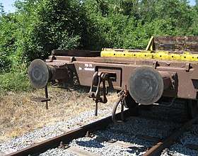
Buffers and chain coupler
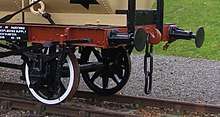
Buffers and chain couplers (also known as "buffers and screw", "screw", and "English" couplers) are the de facto UIC standard railway stock coupling used in the EU and UK, and on some surviving colonial railways, such as in South America and India. These couplers are an assembly of several devices: buffers,[1] hooks and links|screws[2]).
With the modern version of these couplers, the rail vehicles are mated by manually connecting the two hooks with one of the two links which incorporate a turnbuckle screw, drawing together and slightly compressing the buffer pairs, one left and one right on each headstock. This limits slack and lessens shunting shocks in moving trains. In contrast, the semi-automatic Janney Type E coupler experiences significant jarring during mating and shunting. Very early stock had "dummy buffers" which were simple rigid extensions of the frame; these evolved and improved with enclosed mechanical then hydraulic springs.
Characteristics

The standard type of coupling on railways following the British tradition is the buffer and chain coupling used on the pioneering Planet class locomotive of the Liverpool and Manchester Railway of 1830. These couplings followed earlier tramway practice but were made more regular.
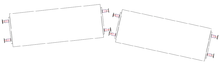
This coupling is still the standard in European countries (except the former Soviet Union, where the SA-3 automatic coupler is used). Coupling is done by a worker who must climb between the cars. First he winds the turnbuckle to the loose position, and then he can hang the chain on the hook. After hanging the chain on the towing hook the turnbuckle handle is stowed on the idle hook to prevent damage to itself, the vehicle, or the brake pipes. Only shunting is permitted with a dangling chain. Disconnected brake pipes must be stowed on dummy connectors, to allow proper operation of the brakes. (The picture shows two coupled cars, with a single brake pipe.)
The hooks and chain hold the carriages together, while the buffers keep the carriages from banging into each other so that no damage is caused. The buffers can be "dumb" or spring-loaded. That means there are no run-in forces on the coupler. The other benefit compared with automatic couplers is that its lesser slack causes smaller forces on curves; there is a lower probability of a broken coupler in a curve than with automatic couplers. The disadvantage is the smaller mass of the freight that can be hauled by hook and chain couplers (maximum 4,000 t or 3,937 long tons or 4,409 short tons).
Early rolling stock was often fitted with a pair of auxiliary chains as a backup if the main coupling failed. This made sense before the fitting of continuous fail-safe braking systems.
On railways where rolling stock always pointed the same way, the chain might be mounted at one end only, as a small cost and weight saving measure.
On German and Scandinavian railways, the left buffer is flatter than the right one, which is slightly more rounded. This provides better contact between the buffers than would be the case if both buffers were slightly rounded.
Variants
Three-link couplings
A peculiarly British practice was the "loose-coupled" freight train, operated by the locomotive crew and a 'Guard' at the rear of the train, the successor to the brakesman of earlier times. This train type used three-link chain couplings for traction and side buffers to accept pushing forces: since such trains were not fitted with an automatic through-train braking system there were no pipes to connect between the vehicles. The last vehicle of the train was a heavily ballasted guard's van with its brakes controllable by a handwheel convenient for the guard. The 'slack' between vehicles was very convenient when starting heavy trains with a relatively low-powered locomotive on the level or a rising gradient. On the driver's command the guard would apply his brake as hard as possible. The driver would then gently reverse to close up the wagons onto their buffers. The locomotive was then driven ahead and it could pick up the load, wagon by wagon, thus giving an easy start up the gradient. Wagons of that era didn't have roller bearings and the grease-lubricated bearings had considerable resistance to start moving, especially on a cold day, so starting wagon-by-wagon greatly reduced the traction force required from the locomotive. The downside of this convenience was that the guard could get badly thrown about as the train changed speed due to the inter-wagon gaps opening or closing. In the worst case these jerks could break a coupling or cause a derailment. A skilled guard would observe or listen to his train and apply or release his brake to keep the last few couplings reasonably taut and act as a shock-absorber. The same effect was seen when the route changed gradient, when going over a hill the rear of the train would catch up with the wagons held back by the locomotive, again, the guard could minimize this. This working of the brake was why the guard was required to prove his route knowledge, same as the driver, before being in charge of a heavy train. Such trains travelled at low speeds and were phased out in the 1970s.[3]
An improvement on this is the "Instanter" coupling, in which the middle link of a three link chain is specially triangular shaped so that when lying "prone" it provides enough slack to make coupling possible, but when this middle link is rotated 90 degrees the length of the chain is effectively shortened, reducing the amount of slack without the need to wind a screw. The closeness of the coupling allows the use of inter-vehicle pipes for train brakes. Three-link and Instanter couplings can be operated entirely from the side of the wagons using a shunter's pole (a pole rather like a substantial broom handle with a hook on the end) and are safer when shunting work is under way. Similarly, the screw-adjustable coupler can be connected by a shunter's pole once it has been unscrewed. Ordinary three-link couplings have been superseded by instanter, screw or buck-eye couplers in UK freight trains today.
Center-buffer-and-chain(s)
On some narrow-gauge lines in Europe and on the Paris Metro a simplified version is used, consisting of a single central buffer with a chain underneath. Sometimes there are two chains, one on each side of the coupler. The chain usually contains a screw-adjustable link to allow close coupling. These variants are also used elsewhere. On sharp curves, a single centre buffer is less likely to be subject to buffer-locking.
Buffer-and-chain on the narrow gauge
Buffer-and-chain couplers do not allow very sharp curves, and there is a buffer-locking problem if pushing the limit. Because of that – and Carl Pihl's successful promotion of the single-buffer Norwegian coupler that he designed to overcome this – conventional buffers-and-chain coupling is rarely employed on narrow-gauge systems: notable exceptions being the railway networks of Senegal/Mali, Tunisia and Côte d'Ivoire/Burkina Faso in Africa, and Queensland and Tasmania in Australia. Narrow gauge railways are often isolated from other railways, so standardization is not so important.
Problems with buffers and chain
Maximum load
The buffers and chain coupling system has a maximum load much less than that of the Janney coupler. They allow around 3,000-4,000 (metric) tonnes total train weight depending on the how they are constructed. The Janney coupler sometimes is built for 32,000 tonnes.
Buffer-locking
On sharp reverse curves, the buffers can get buffer-locked by slipping over – and onto the back of – an adjacent buffer.[4] Although careful track design makes this occurrence rare, an accident at a Swiss station in the 1980s was caused by buffer-locked wagons. Buffer-lock could be caused on the very sharp switches by the older, rounded buffers. The newer buffers are rectangular and they are wider than they are tall. They are not as flat, so they rarely cause buffer-locking. Buffers and chain coupler allow curves to have around 150 m (492.13 ft) radius, but so sharp S-curves are not allowed. If it weren't for the couplers, much sharper curves could be allowed, on the condition the train is not too long. Tramways exist with 20 m (65.62 ft), or less curve radius, with center couplers.
Variation with gauge
The width between the buffers tends to increase as the gauge increases or decrease as the gauge decreases, so that if wagons are changed from one gauge to another, the buffers will no longer match. This occurs because the buffers are originally extensions of the frames, which are spaced according to the gauge. Conversely, as gauge gets smaller, the distance between the buffers reduces also. The height of the buffers is usually lower on narrow gauge railways, corresponding to the generally lower height of the rolling stock. Narrow gauge railway often use centre couplers without buffers instead. In short, when rebuilding wagons from one gauge to another, more work is needed.
However, in the case of Iberian broad gauge railways, the buffer's height and spacing is the same as for the standard gauge railways in Europe including Great Britain in order to allow through running of rolling stock by the use of bogie exchange.
Dimensions
Buffers and chain couplers tend to have the two buffers spaced according to the gauge, but especially in Europe this is modified to the standard gauge value to allow interrunning by means of bogie exchange.
Dimensions showing variation of spacing by gauge.
| Name | Gauge | Height | Separation | Region |
|---|---|---|---|---|
| Standard gauge | 1,435 mm (4 ft 8 1⁄2 in) | 1,054 mm (41.5 in) | 1,727 mm (68.0 in)[5] | Great Britain, European mainland |
| Metre gauge | 1,000 mm (3 ft 3 3⁄8 in) | 0,756 mm (29.8 in) | 1,248 mm (49.1 in) | Senegal and Mali [6] Burkina Faso and Ivory Coast. |
| Broad gauge | 1,520 mm (4 ft 11 27⁄32 in) | 1,063 mm (41.9 in) | 1,727 mm (68.0 in) | Dual-gauge (Europe/Russia) sleeping car[7] |
| Broad gauge | 1,668 mm (5 ft 5 21⁄32 in) Iberian gauge | 1,050 mm (41.3 in) | 1,720 mm (67.7 in) | Spain and Portugal |
| Broad gauge | 1,676 mm (5 ft 6 in) | 1,067 mm (42.0 in) | 1,955 mm (77.0 in) | India, Pakistan and Sri Lanka |
Gallery
 Buffer And Chain
Screw Couplers
on German Loco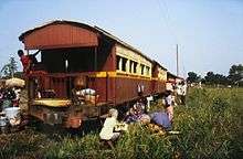
 Buffer And Chain
3Link Couplers
on Tank Wagon Buffer And Chain
3Link Couplers
on Tank Wagon.jpg) Buffer And Chain
Buffer And Chain
Screw Couplers
CoilSpring Buffers Left
Hydraulic Buffers Right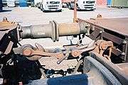 Buffer And Chain
Screw Couplers
on Goods Wagons Buffer And Chain
Screw Couplers
in Ride Mode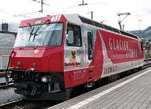 Switzerland Rhätische Bahn (1,000 mm or 3 ft 3 3⁄8 in) "Centre-buffer-&-double chain coupler", called Equalising lever coupler
 Balance lever in front of buffer support
 Balance lever behind buffer support (Equalising lever coupler)
References
- EN 15551:2009+A1:2010 Railway applications – Railway rolling stock – Buffers
- EN 15566-2009+A1:2010 Railway applications – Railway rolling stock – Draw gear and screw coupling
- "Archived copy". Archived from the original on 2006-09-26. Retrieved 2006-11-12.CS1 maint: archived copy as title (link)
- No locking
- Steam Spirit, Vol 1, p 129
- Jane's World Railways 1969-1970 edition
- Railway Gazette International Sept 2012, p 108
External links

- Buffer and chain coupling