Type 91 torpedo
| Type 91 torpedo | |
|---|---|
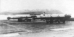 Type 91 torpedoes aboard an aircraft carrier. | |
| Type | Aerial torpedo |
| Place of origin | Empire of Japan |
| Service history | |
| In service | 1931–1945 |
| Used by | Japanese Navy |
| Wars | World War II |
| Production history | |
| Designer | Rear Admiral Seiji Naruse and his team |
| Designed | 1930–1945 |
| Unit cost | 20,000 yen (in 1941) |
| Specifications | |
| Weight | 848 kg (1,870 lb) |
| Length | 5.270 m (17.29 ft) |
| Diameter | 45 cm (18 in) |
|
| |
| Maximum firing range | 2,000 m |
| Warhead weight | 323.6 kg (713 lb) high explosive, 235 kg (518 lb) for warhead rev.3 |
|
| |
| Engine |
Wet-heater type, 8-cylinder radial engine 200hp |
| Wingspan | 69 cm in the air, 66 cm in the water |
| Speed | 42 knots (77.8 km/h) |
Steering system | Gyrocompass-guided vertical-rudder control system, gyroscope-guided anti-rolling controller system |
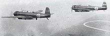
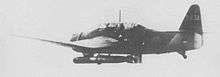
Launch platform | Single-engine carrier-based attack aircraft, twin-engine land-based attack aircraft |
The Type 91 was an aerial torpedo of the Imperial Japanese Navy designed to be launched from an aircraft. It was in service from 1931 to 1945. It was used in naval battles in World War II and was specially developed for attacks on ships in shallow harbours.
The Type 91 aerial torpedo had two unique characteristics. First, it used wooden aerodynamic stabilizers attached to the tail fins which were shed upon water entry. Secondly, it engaged an angular acceleration control system (PID controller) to control rolling movements, which was very advanced for its time. This system made it possible to release the Type 91 not only at a cruising speed of 180 knots at an altitude of 20 m (66 ft), but also in a power-glide torpedo-bombing run at the maximum speed of the Nakajima B5N or Kate, 204 knots.
The Type 91 torpedo was 450 mm (17-3/4 in) in diameter. There were five models put into service, with high explosive warheads weighing 213.5 kg to 526.0 kg (or 470 lb to 1160 lb) and having effective ranges of 1,500 m to 2,000 m (or 1,600 yd to 2,200 yd) at 42 knots.
Since the Type 91 torpedo was the only practical aerial torpedo of the Imperial Japanese Navy, it was simply known as the Koku Gyorai, or aerial torpedo. Surface warships and submarines used other types of torpedoes, namely the Type 93 and Type 95 respectively, while the Type 97 torpedo was designed for use by midget submarines.
Specifications
The torpedo measured 18 feet (5.5 m) in length, with a diameter of 1 foot 5.7 inches (0.450 m), and weighed 1,841 pounds (835 kg), with an explosive charge of 452 pounds (205 kg). It had a range of 2,200 yards (2,012 m) and a speed of 42 knots. A slight variant was used to sink HMS Prince of Wales and HMS Repulse, launched from Mitsubishi G4M "Betty" bombers in an action in the South China Sea three days after Pearl Harbor on December 10, 1941.[1]
Variants
Below is the list of the series of Type 91 aerial torpedo production models.[2]
| Main body | Warhead | High explosive (kg) | Speed (knots) | Range (m) | Total Length (m) | Diameter (m) | Total Weight (kg) | Head Length (m) | Head Weight (kg) | Comments |
|---|---|---|---|---|---|---|---|---|---|---|
| Type91 | Type91 | 149.5 | 42 | 2,000 | 5.270 | 0.45 | 784 | 0.958 | 213.5 | – |
| Rev.1 | Rev.1 | 149.5 | 42 | 2,000 | 5.270 | 0.45 | 784 | 0.958 | 213.5 | Supported shedding wooden tail-plates in 1936, first model considered for German LT 850 version |
| Rev.2 | Rev.2 | 204.0 | 42 | 2,000 | 5.470 | 0.45 | 838 | 1.158 | 276.5 | Body reinforced in 1938, anti-rolling controller added in 1941, 2nd version considered for German LT 850 version |
| Rev.3 | Rev.3 | 235.0 | 42 | 2,000 | 5.270 | 0.45 | 848 | 1.460 | 323.6 | – |
| Rev.3 | Rev.3_rev. | 235.0 | 42 | 2,000 | 5.270 | 0.45 | 848 | 1.460 | 323.6 | Reinforced warhead |
| Rev.5 | Rev.3_rev. | 235.0 | 41 | 1,500 | 5.270 | 0.45 | 848 | 1.460 | 323.6 | Precision forging and stainless steel cast body |
| Rev.5 | Rev.7 | 420.0 | 41 | 1,500 | 5.710 | 0.45 | 1080 | 1.900 | 526.0 | Warhead designed to breach the armor of US battleships |
The Type 91 (modification 2), was a shallow-water aerial torpedo that was designed for and used in the attack on Pearl Harbor in 1941. Wooden fins and a softwood breakaway nose cone were added to allow for launching into shallow water at low altitudes.[3]
There were two versions in the Type 91 warhead rev.3, differing in designed maximum launch speeds.
Later, heavier models had a decreased range.
Other Japanese aerial torpedoes
In spring 1944, the Yokosuka air arsenal began development of the Shisei Gyorai M (trial model torpedo M), or simply the Two tonne torpedo. This was an enlarged version of the Type 91 aerial torpedo and was 533mm (21 in) in diameter, 7.10 m (23 ft) long, weighing 2,070 kg, and carrying a 750 kg warhead.[4] It would have been the largest aerial torpedo in the Imperial Japanese Navy Air Force, but the operating concept became outdated and the project was never completed. However, the Type 91 aerial torpedo project members did not regard it as a part of the Type 91 series.
Type 91 history
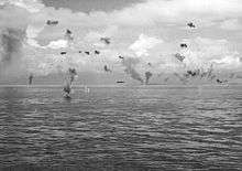
_during_the_Battle_of_Santa_Cruz_Islands_on_26_October_1942.jpg)
- Chronological Table
- 1931 – Type 91 aerial torpedo is put into service, production begins.
- 1936 – Revision 1. Self-detachable wooden plates are introduced.
- 1937 – Launch-tests at 500m and 1,000m with wooden damper.
- 1939 – Revision 2 starts production. Not running true after water entry is identified as a major problem.
- 1941 – Revision 2 clears the shallow water launching test due to the introduction of an anti-rolling controller. Battle of Pearl Harbor, sinking of HMS Prince of Wales and HMS Repulse.
- 1941 – Revision 3 starts production.
- 1942 – Indian Ocean raid, Battle of the Coral Sea, Battle of Midway, Battle of the Santa Cruz Islands. August 2: Type 91 torpedo technology reaches Nazi Germany via IJN sub I-30[5]
- 1943 – Revision 5 starts production.
- 1944 – Battle of the Philippine Sea, Aerial Battle of Taiwan-Okinawa.
Initial development
Rear Admiral Seiji Naruse led the team in charge of the initial development of the Type 91 aerial torpedo at the Yokosuka Naval Arsenal. The team was known as the Ninety One Association and included Lt Cmdr Haruo Hirota, Lt Cmdr Makoto Kodaira (Matsunawa), Naval Assistant Manager Iyeta, Naval Engineer Noma, Naval Engineer Moritoshi Maeda, Lieutenant Hidehiko Ichikawa, and Teruyuki Kawada, a university student who was a naval apprentice.
Captain Fumio Aiko was in charge of further development of the torpedo from 1931. Captain Aiko managed the team as it developed an effective aerial torpedo and anti-rolling controller. He considered the Type 91 aerial torpedo to be his great achievement.
Delayed development
At the beginning of 1934, Kan-Pon or the Imperial Japanese Navy Technical Department, an operating division of the Ministry of the Navy of the Imperial Japanese government, which had the primary responsibility for naval weapon systems, had their own plan for a Japanese aerial torpedo. In their concept, a big flying boat was to carry a variant of the heavy Type 93 oxygen torpedoes to launch at long range, and then turn back towards safety. This eventually proved to be an unrealistic desk plan. Kan-Pon confidentially developed their own Type 94 torpedo and even ordered a halt to production of the Type 91. This significantly delayed the development schedule of the Type 91 and frustrated the project members.
Wooden tail stabilizers added
The project team developed Kyoban wooden aerodynamic stabilizer plates for the Type 91's tail fins as revision 1 in 1936. These stabilized the torpedo in flight to ensure the proper angle for water entry and were designed to shear off on entry to the water, preventing the torpedo from diving too deep. The team demonstrated their effectiveness in tests at altitudes of both 500 m and 1,000 m the following year.
The original Type 91 was considered to have a frail body, and so this was strengthened in a new model in 1938 known as revision 2.
Anti-rolling controller developed
Type 91 aerial torpedoes won admiration for their effective anti-rolling controller and acceleration control system. Before the anti-rolling controller was introduced, the early versions of the Type 91 had serious problems, as did all other aerial torpedoes of the time. When released at high speed, it had a tendency to make a double-roll in the air. When released into heavy seas, a spin could be imparted by the hard impact on water entry. Other issues included: the running direction veering on water impact; not running horizontally after water entry, but continuing vertically to either stick in the bottom of shallow water or be crushed by the water pressure (at a depth of 100 m or so); jumping back out of the water; skipping along the water surface; or even running backwards. Only very experienced aviators could be sure of a clean torpedo bombing run, and then only when operating over a calm sea. A tumbling torpedo will run out of control once it hits the water. The gyrocompass and the depth meter may work well, but the torpedo cannot control the running direction by tail rudders unless they are initially in the neutral position. Once the torpedo rolls, the horizontal and vertical rudders lose their positions, resulting in a runaway.
The specification for the launch speed of aircraft was increased from 130 knots to 180 knots, with the expectation that it would be increased again. The engineers and scientists of the Type 91 project concluded that any aerial torpedo needed an anti-rolling system with not only a damping stabilizer function but also an acceleration controlling function. Without these features any torpedo would be highly likely to fall into an unstable state. The idea of acceleration-control, or counter-steering, was at the time widely considered to be impossible.
A breakthrough on aerial torpedo design was made with the anti-rolling controller invented first by Iyeda, assistant manager of the arsenal workmen, in spring 1941. Ten days later, while the Iyeda system was being tested, Naval Engineer Noma invented another system. It functioned in a similar way, but with a different mechanism. During the prototype tests, Noma's system was found to be the better, having less time lag in its responses. So the Noma system was adopted for the next production version of Type 91 and it went into final testing in August 1941, making practical the use of aerial torpedoes both in rough seas and in shallow waters. It enabled the Type 91 rev.2 to run under water no deeper than 20 meters, with experienced pilots learning to launch their torpedo so as to sink to a depth of no more than 10 meters.
Increase in explosive weight
The anti-rolling controller also made it possible for the Type 91 to carry a heavier warhead. The Type 91 rev.1 warhead weighed 213.5 kg with a high explosive charge of 149.5 kg, but the rev.2 warhead weighed 276 kg with 204 kg of high explosive. Warhead rev.7, which was carried by twin-engine bombers, weighed 526 kg and boasted a high explosive charge of 420 kg; this was designed to pierce the reinforced armour plates of the latest US Navy ships.
Main components (Type 91.rev.2)
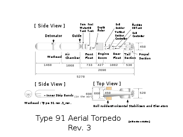
Warhead
Length = 1,460 mm
When a torpedo hits a ship, the inertia forces the initiator to thrust forward and ignite its high explosive. The high explosive in the warhead will not detonate unless initiated as designed. An aerial torpedo, released at an altitude of 100 m, is falling at nearly Mach 0.5 on water entry and receives over 100G at the hard impact on the water surface. The Type 91 warhead had five reinforced bands on the front-bottom of the inner shell, lap welded in the shape of cut lower half star, or the superposition of the letter T and the letter Λ.
Air chamber
L = 1,068 mm (42⅛in)
The air chamber is a thin-shelled cylinder made of nickel-chromium-molybdenum steel. This tough steel alloy was originally developed for the steel armor plate of battleships. The chamber is charged with highly compressed air at 175–215 atm, which burns with fuel oil to produce the driving power. Its pressure drops to around 50 atm (710 psi) while running 2,000 m (6,600 ft).
Front float
L = 733 mm (28⅞in)
The front float section has a pure water tank, a fuel oil tank and a depth meter. The depth meter is placed at the bottom of the section to detect the water depth. It detects the displacement level and controls the horizontal tail rudders' (or elevators)' accordingly, so that the torpedo maintains level running under water. The horizontal tail rudder controller is operated by the rod connection mechanism from the depth meter in the front float section. The horizontal tail rudders are locked at their uppermost position while the torpedo falls to the water surface.
Engine housing
L = 427 mm (16⅞ in)
This section is exposed to incoming water to help cool the engine. It has a starter, a Chowaki or pressure regulator, a wet-heat chamber and a main engine. The starter starts controllers, one for vertical tail rudders, and another for roll rudders for anti-rolling in both side wing rudders.
The pressure regulator is called a Chowaki or harmonizing system. It is a two-stage pressure regulator with twin pressure-tunable regulation valves. It steps down the pressure of compressed air at 215–50 atm (3,000—711 psi) in the air chamber to a constant flow of high-pressure air at 10 atm (142 psi). While the air pressure is declining as the torpedo is running under the water, the pressure regulator feeds the constant high-pressure air to the engine intake aspirator and keeps the running speed constant at 43 knots.
The wet-heat chamber is made of heat-resistant steel. Type 91 aerial torpedoes use a wet-heater engine like almost all other torpedoes in World War II. The general wet heater burning method drastically improved the combustion efficiency of torpedo engines. It burns a mixed gas of fuel oil and the high-pressure air with a spray of pure water in the wet-heat block to produce burning steam gas which is fed to the engine. The high-pressure fuel oil gas is burnt at a temperature of 800 degrees C. The sprayed pure water mists into the combustion gas, which produces a vapour explosion, resulting in completely gasified fuel oil combustion.
The main engine is an 8-cylinder single-row radial piston engine. A single drive shaft runs to the tail and the screws. The main engine is started when the torpedo hits the water. A thick safety bolt is inserted into the starter when the weapon is loaded on an aircraft. The bolt is pulled out from the torpedo when it is released and remains underneath the fuselage of aircraft.
Rear float
L = 1,002 mm (39½in)
This rear float section has a machine oil tank, a rudder controller, an anti-rolling controller, and roll rudders on both sides. The machine oil tank is centre-mounted in the rear float section. The rudder controller is a general gyrocompass controlled system, which steers the vertical rudders to keep the longitudinal axis of the torpedo in the sensed direction straight. Both the vertical rudder controller and the anti-rolling controller had their own gyroscope, which start rotating when the torpedo is released from an aircraft. Each gyro has dual ring support mechanisms to allow them to move freely.
Anti-rolling controller
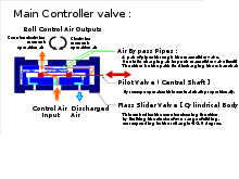
The anti-rolling controller is a gyro-controlled air valve system which steers the roll rudders on both sides of a torpedo and is composed of a gyroscope, a main controller, and an output booster. The most significant part is the main controller.
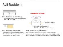
A spinning gyroscope senses the degree of roll of the torpedo, and the controller then centres the roll, steering roll-rudders on both sides at an angle in the range of ±22.5°. The main controller controls two output air valves to steer and countersteer the roll rudders by detecting the tilted degree of the torpedo via the pilot valve. It countersteers the roll rudders when the torpedo is rolling back to neutral position, which results in detecting the acceleration of the rolling angular velocity derivative with respect to time. The output booster or auxiliary valve has two inlets and two outlet ports. The output booster works as a pair of air shutoff valves. It is connected in cascade to the two output ports of the main controller. It switches on and off directly the two powerful high-pressure controlling air flows, one for clockwise twist and the other for counter-clockwise twist of the roll rudders. This is largely to ensure proper operation in heavy impact conditions.
Tail section
L = 530 mm (to the tip end of propelling screw hub) (20⅞i n)
Bevel gears drive coaxial contra-rotating double 4-bladed screws to propel the torpedo under the water and keep it running straight. The tail section has vertical and horizontal stabilizer fins in a cross. Each fin has a controlling rudder in aft. Horizontal fins and rudders have a wide span in a longitudinal direction and work proportionally, while vertical fins are small, and rudders have a very short span.
Screws
The propeller screws were coaxial contra-rotating double screws, with 4 propeller blades each. Each screw was wrought from a cubical mass of SK chromium-molybdenum alloy steel into a bold cross shape and punched through the centre. Hammering punches of 1 tons and 3 tons shaped the 4 blades. The propeller sections were compactly designed to allow the front screw and the rear screw to be only 5 mm apart.
Kyoban stabilizer plates
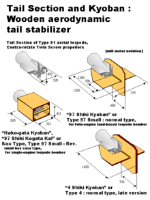
The Type 91's tail fins were fitted with Kyoban wooden aerodynamic stabilizer plates. Introduced in 1936 these stabilized the torpedo in flight and helped to ensure the proper angle for water entry. The plates were designed to shear off on water entry, absorbing energy and preventing the torpedo from diving too deep. The aerodynamic wooden plates stabilized the torpedo in both the vertical and horizontal axes and provided drag to ensure the torpedo struck the water at or near the proper water entry angle despite the inevitable variations in drop altitudes and air speeds encountered in combat. The structure was simple and worked well, as seen at Pearl Harbor, which was generally considered too shallow for aerial torpedoes prior to the attack. The Kyoban was so effective the US Navy copied it for their Mark 13 torpedo after observing it in action at the Battle of the Coral Sea.
Two versions of the Kyoban stabilizer were used: A box-shaped version for single-engine carrier-based torpedo-bombers Nakajima B5N and Nakajima B6N and a cross-shaped version For twin-engine land-based torpedo-bombers G3M, G4M, P1Y, and Ki-67. The cross-shaped version used longer plates to lower drag resistance but needed more clearance under the fuselage. In the case of land-based torpedo-bomber aircraft, a plate was set inside the bomb bay to smooth the airflow, otherwise the vortex coming in the bomb bay would disturb the torpedo at release.
Steering mechanism
There are three separate steering systems:
- The full steering system: The vertical rudder system steers the torpedo left or right by switching the rudders to one of full-right, neutral or full-left in response to signals from the gyroscope. This system responds relatively slowly to deviations from the correct running direction.
- The proportional steering system: The horizontal rudder system changes the angle of the rudders to cause the torpedo to run at a deeper or shallower depth in response to signals from the depth meter. This system has a moderately rapid response to deviations from the appropriate running depth.
- The angular velocity steering system: The two roll-rudders switch to one of full-up, neutral or full-down in response to signals from the anti-rolling controller. When the controller detects the torpedo returning to the centre position, the system counter-steers the roll rudders in opposite directions. This system has a rapid response to deviations in running direction.
The three systems operate simultaneously to maintain the appropriate direction, depth and attitude of the torpedo while running.
Production sites
The Type 91 was researched and developed at Yokosuka Naval Arsenal in Kanagawa Prefecture. It was first produced at the Mitsubishi-Urakami Ordnance Works division of Mitsubishi Heavy Industries. Later, the Imperial Japanese Navy established two manufacturing sites: Suzuka Naval Arsenal in Mie Prefecture; and Kawatana Naval Arsenal, a branch of Sasebo Naval Arsenal, in Nagasaki Prefecture. The Mitsubishi-Urakami Ordnance Works plant at Kawatana specialized in torpedo production and was destroyed by the atomic bomb dropped on Nagasaki.[6]
Technology transfer to Germany
Germany approached Japan requesting the transfer of Japanese aerial torpedo technology. The Imperial Japanese Navy not only sent the plans, but also a number of Type 91 aerial torpedoes to Germany in response. They arrived in Nazi hands on August 2, 1942, courtesy of Japanese submarine I-30[5] as part of a yanagi mission. It was designated the Lufttorpedo LT 850 in German service. The weight of the LT 850 German version was somewhat lighter at 810 kg (1,786 lb), with a 5.43 meter length.[7]
Germany wished to acquire the knowledge behind the Imperial Japanese Navy Air Service's aerial torpedo technology in order to more effectively attack the Allied transport ships steaming in the Mediterranean Sea.[8] It had previously imported Italian-made aerial torpedoes, which became unavailable following the Italian Armistice of Cassibile with the Allies in September 1943. The indigenous German aerial torpedo designs were badly restricted in launch speed and launch altitude.
Post-war commemoration
Some 30 years after the war, surviving members of the development team raised money to privately publish a small book, Koku Gyorai Note or Aerial Torpedo Notebook.[9]
Type 91 torpedoes are currently displayed at the Etajima school of Japan Maritime Self-Defense (the Maritime Self Defense Force 1st Technical School) and Shimofusa Base. They are missing the roll rudders. An excavated Type 91 aerial torpedo is preserved at the Resource Museum in JGSDF Camp Naha, 1st Combined Brigade of The Western Army, JGSDF, located in Naha city, Okinawa. It retains the original features. It was picked up as unexploded ordnance by a bomb-disposal unit of the JGSDF. A captured Type 91 aerial torpedo is displayed at the US Naval Academy, Annapolis, Maryland. It rests on two supports flanking a pathway in a small park in front of the Academy's Dahlgren Hall. Displayed on the other side of the pathway is a Type 93 Japanese Long Lance ship-launched torpedo.
References
Bibliography
- Ichikawa, Hidehiko; Kodaira, Makoto; Kawada, Teruyuki (July 25, 1985). "Kyu Ichi Kai – Koku Gyorai Note" or 91 Association – Aerial Torpedo Notebook. Tokyo, Japan: Iyeno Hikari Private Publishing Service. ISBN. – text in Japanese, privately printed book.
- "Warship Carrier Zuikaku Action Report No.7, Battle of the Coral Sea". "Kaigun Koku Bokan Sento Kiroku" or Naval Aircraft Carrier Action Reports. Tokyo, Japan: Athen-shobo. July 2002. ; photographic print copies of Imperial Japanese Navy Action Reports, text in Japanese.
- "p196 – p222, Ozawa, Kyuno Joe; "Mitsubishi Type 4 Army Bomber Aircraft"". Document of Historical Aircraft with Japan Making, Special Thanks 600 Issue of Airrview, last volume. Tokyo, Japan: Kanto-sha. 1994. ISBN. – text in Japanese, Prof. Ozawa is the designer of Ki-69.
- Seko, Tsutomu (December 1986). "Raigeki no Tsubasa" or Wings of Torpedo Bombers. Tokyo, Japan: Kojin-sha. ISBN. – text in Japanese, Seko was one of the last torpedo bombardiers of B6Ns.
- Akimoto, Minoru (June 1995). "Nihon Gunyoki Kokusen Zenshi, Dai 4 kan" or Japanese military aircraft air combat complete history, volume 4. Tokyo, Japan: Green arrow sha. ISBN 4-7663-3174-5. - text in Japanese.
- (August, 1945), Resources from Torpedo bombing section, Kawatana branch, Naval aerial technology arsenal, Imperial Japanese Navy.
- (August, 1945), Resources from the 1st torpedo section, Kawatana naval arsenal production firm, Imperial Japanese Navy.
Notes
- ↑ "Japan Torpedoes of World War II". NavWeaps.com. Archived from the original on 2009-08-04. Retrieved 2009-08-05.
- ↑ p.24, Ichikawa, Hidehiko; Table 1-2 List of Aerial Torpedo Koku Gyorai Note
- ↑ Gannon, Robert (April 30, 1996). Hellions of the Deep. Pennsylvania State University Press. pp. 49–50. ISBN 978-0-271-01508-8. Retrieved 2009-08-05.
- ↑ Minoru, Akimoto; "Nihon Gunyoki Kokusen Zenshi, volume 4", Green Arrow sha, June, 1995, p.383
- 1 2 "Submarine I-30: Tabular Record of Movement". combinedfleet.com. Archived from the original on 2010-11-17. Retrieved 15 September 2010.
- ↑ "UNITED STATES STRATEGIC BOMBING SURVEY SUMMARY REPORT (Pacific War) THE EFFECTS OF THE ATOMIC BOMBS". U.S. Strategic Bombing Survey. p. 24. Archived from the original on 2008-05-16. Retrieved 2018-09-15.
- ↑ ""Luftfahrtgeräte - Abwurfwaffen - Torpedos und Bombentorpedos" (in German)". luftarchiv.de. Luftarchiv. Archived from the original on 2016-03-04. Retrieved August 10, 2018.
- ↑ p.13, Fumio Aikō; Koku Gyorai Note
- ↑ p.278, Ichikawa, Hidehiko; Postface, Koku Gyorai Note