Selective laser melting
Selective laser melting (SLM) or direct metal laser sintering (DMLS) is a rapid prototyping, 3D printing, or additive manufacturing (AM) technique designed to use a high power-density laser to melt and fuse metallic powders together.[1][2] In many SLM is considered to be a subcategory of selective laser sintering (SLS). The SLM process has the ability to fully melt the metal material into a solid three-dimensional part unlike SLS.
History
Selective laser melting, one of the several 3D printing technologies, started in 1995 at the Fraunhofer Institute ILT in Aachen, Germany, with a German research project, resulting in the so-called basic ILT SLM patent DE 19649865. Already during its pioneering phase Dr. Dieter Schwarze and Dr. Matthias Fockele from F&S Stereolithographietechnik GmbH located in Paderborn collaborated with the ILT researchers Dr. Wilhelm Meiners and Dr. Konrad Wissenbach. In the early 2000s F&S entered into a commercial partnership with MCP HEK GmbH (later on named MTT Technology GmbH and then SLM Solutions GmbH) located in Luebeck in northern Germany. Today Dr. Dieter Schwarze is with SLM Solutions GmbH and Dr. Matthias Fockele founded Realizer GmbH.
The ASTM International F42 standards committee has grouped selective laser melting into the category of "laser sintering", although this is an acknowledged misnomer because the process fully melts the metal into a solid homogeneous mass, unlike selective laser sintering (SLS) which is a true sintering process. Another name for Selective Laser Melting is Direct Metal Laser Sintering (DMLS), a name deposited by the EOS brand, however misleading on the real process because the part is being melted during the production, not sintered, which mean the part is fully dense.[3] This process is in all points very similar to other SLM processes, and is often considered as a SLM process.
A similar process is electron beam melting (EBM), which uses an electron beam as energy source.[4]
Process
DMLS uses a variety of alloys, allowing prototypes to be functional hardware made out of the same material as production components. Since the components are built layer by layer, it is possible to design organic geometries, internal features and challenging passages that could not be cast or otherwise machined. DMLS produces strong, durable metal parts that work well as both functional prototypes or end-use production parts.[5]
The process starts by slicing the 3D CAD file data into layers, usually from 20 to 100 micrometres thick, creating a 2D image of each layer; this file format is the industry standard .stl file used on most layer-based 3D printing or stereolithography technologies. This file is then loaded into a file preparation software package that assigns parameters, values and physical supports that allow the file to be interpreted and built by different types of additive manufacturing machines.
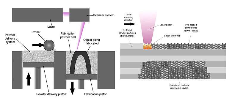
With selective laser melting, thin layers of atomized fine metal powder are evenly distributed using a coating mechanism onto a substrate plate, usually metal, that is fastened to an indexing table that moves in the vertical (Z) axis. This takes place inside a chamber containing a tightly controlled atmosphere of inert gas, either argon or nitrogen at oxygen levels below 500 parts per million. Once each layer has been distributed, each 2D slice of the part geometry is fused by selectively melting the powder. This is accomplished with a high-power laser beam, usually an ytterbium fiber laser with hundreds of watts. The laser beam is directed in the X and Y directions with two high frequency scanning mirrors. The laser energy is intense enough to permit full melting (welding) of the particles to form solid metal. The process is repeated layer after layer until the part is complete.
The DMLS machine uses a high-powered 200 watt Yb-fiber optic laser. Inside the build chamber area, there is a material dispensing platform and a build platform along with a recoater blade used to move new powder over the build platform. The technology fuses metal powder into a solid part by melting it locally using the focused laser beam. Parts are built up additively layer by layer, typically using layers 20 micrometers thick.[6]
Materials
Many Selective Laser Melting (SLM) machines operate with a work space up to 400 mm (15.748 in) in X & Y and they can go up to 400 mm (15.748 in) Z. Some of the materials being used in this process can include copper, aluminium, stainless steel, tool steel, cobalt chrome, titanium and tungsten. In order for the material to be used in the process it must exist in atomized form (powder form). Currently available alloys used in the process include 17-4 and 15-5 stainless steel, maraging steel, cobalt chromium, inconel 625 and 718, aluminum AlSi10Mg, and titanium Ti6Al4V.[7]
| Materials |
|---|
| Copper |
| Tool steel |
| Cobalt chrome |
| Titanium |
| Tungsten |
| Aluminium |
| Stainless steel |
| Gold |
Applications
The types of applications most suited to the selective laser melting process are complex geometries & structures with thin walls and hidden voids or channels on the one hand or low lot sizes on the other hand. Advantage can be gained when producing hybrid forms where solid and partially formed or lattice type geometries can be produced together to create a single object, such as a hip stem or acetabular cup or other orthopedic implant where oseointegration is enhanced by the surface geometry. Much of the pioneering work with selective laser melting technologies is on lightweight parts for aerospace[8] where traditional manufacturing constraints, such as tooling and physical access to surfaces for machining, restrict the design of components. SLM allows parts to be built additively to form near net shape components rather than by removing waste material.[9]
Traditional manufacturing techniques have a relatively high set-up cost (e.g. for creating a mold). While SLM has a high cost per part (mostly because it is time-intensive), it is advisable if only very few parts are to be produced. This is the case e.g. for spare parts of old machines (like vintage cars) or individual products like implants.
Tests by NASA's Marshall Space Flight Center, which is experimenting with the technique to make some difficult-to-fabricate parts from nickel alloys for the J-2X and RS-25 rocket engines, show that difficult to make parts made with the technique are somewhat weaker than forged and milled parts but often avoid the need for welds which are weak points.[8]
This technology is used to manufacture direct parts for a variety of industries including aerospace, dental, medical and other industries that have small to medium size, highly complex parts and the tooling industry to make direct tooling inserts. DMLS is a very cost and time effective technology. The technology is used both for rapid prototyping, as it decreases development time for new products, and production manufacturing as a cost saving method to simplify assemblies and complex geometries.[10] With a typical build envelope (e.g., for EOS's EOSINT M280[11]) of 250 x 250 x 325 mm, and the ability to ‘grow’ multiple parts at one time,
The Northwestern Polytechnical University of China is using a similar system to build structural titanium parts for aircraft.[12] An EADS study shows that use of the process would reduce materials and waste in aerospace applications.[13]
On September 5, 2013 Elon Musk tweeted an image of SpaceX's regeneratively-cooled SuperDraco rocket engine chamber emerging from an EOS 3D metal printer, noting that it was composed of the Inconel superalloy.[14] In a surprise move, SpaceX announced in May 2014 that the flight-qualified version of the SuperDraco engine is fully printed, and is the first fully printed rocket engine. Using Inconel, an alloy of nickel and iron, additively-manufactured by direct metal laser sintering, the engine operates at a chamber pressure of 6,900 kilopascals (1,000 psi) at a very high temperature. The engines are contained in a printed protective nacelle, also DMLS-printed, to prevent fault propagation in the event of an engine failure.[15][16][17] The engine completed a full qualification test in May 2014, and is slated to make its first orbital spaceflight in April 2018.[18]
The ability to 3D print the complex parts was key to achieving the low-mass objective of the engine. According to Elon Musk, "It’s a very complex engine, and it was very difficult to form all the cooling channels, the injector head, and the throttling mechanism. Being able to print very high strength advanced alloys ... was crucial to being able to create the SuperDraco engine as it is."[19] The 3D printing process for the SuperDraco engine dramatically reduces lead-time compared to the traditional cast parts, and "has superior strength, ductility, and fracture resistance, with a lower variability in materials properties."[20]
Industry applications
- Aerospace – Air ducts, fixtures or mountings holding specific aeronautic instruments, laser-sintering fits both the needs of commercial and military aerospace
- Manufacturing – Laser-sintering can serve niche markets with low volumes at competitive costs. Laser-sintering is independent of economies of scale, this liberates you from focusing on batch size optimization.
- Medical – Medical devices are complex, high value products. They have to meet customer requirements exactly. These requirements do not only stem from the operator’s personal preferences: legal requirements or norms that differ widely between regions also have to be complied with. This leads to a multitude of varieties and thus small volumes of the variants offered.
- Prototyping – Laser-sintering can help by making design and functional prototypes available. As a result, functional testing can be initiated quickly and flexibly. At the same time, these prototypes can be used to gauge potential customer acceptance.
- Tooling – The direct process eliminates tool-path generation and multiple machining processes such as EDM. Tool inserts are built overnight or even in just a few hours. Also the freedom of design can be used to optimize tool performance, for example by integrating conformal cooling channels into the tool.[21]
Other applications
- Parts with cavities, undercuts, draft angles
- Fit, form, and function models
- Tooling, fixtures, and jigs
- Conformal cooling channels
- Rotors and impellers
- Complex bracketing[22]
Potential
Selective laser melting or additive manufacturing, sometimes referred to as rapid manufacturing or rapid prototyping, is in its infancy with relatively few users in comparison to conventional methods such as machining, casting or forging metals, although those that are using the technology have become highly proficient. Like any process or method selective laser melting must be suited to the task at hand. Markets such as aerospace or medical orthopedics have been evaluating the technology as a manufacturing process. Barriers to acceptance are high and compliance issues result in long periods of certification and qualification. This is demonstrated by the lack of fully formed international standards by which to measure the performance of competing systems. The standard in question is ASTM F2792-10 Standard Terminology for Additive Manufacturing Technologies.
Difference from selective laser sintering (SLS)
The use of SLS refers to the process as applied to a variety of materials such as plastics, glass, and ceramics, as well as metals. What sets SLS apart from other 3D printing process is the lacked ability to fully melt the powder, rather heating it up to a specific point where the powder grains can fuse together, allowing the porosity of the material to be controlled. On the other hand, SLM can go one step further than SLS, by using the laser to fully melt the metal, meaning the powder is not being fused together but actually liquified long enough to melt the powder grains into a homogeneous part. Therefore, SLM can produce stronger parts because of reduced porosity and greater control over crystal structure, which helps prevent part failure. However, SLM is only feasible when using a single metal powder.
Benefits
DMLS has many benefits over traditional manufacturing techniques. The ability to quickly produce a unique part is the most obvious because no special tooling is required and parts can be built in a matter of hours. Additionally, DMLS allows for more rigorous testing of prototypes. Since DMLS can use most alloys, prototypes can now be functional hardware made out of the same material as production components.
DMLS is also one of the few additive manufacturing technologies being used in production. Since the components are built layer by layer, it is possible to design internal features and passages that could not be cast or otherwise machined. Complex geometries and assemblies with multiple components can be simplified to fewer parts with a more cost effective assembly. DMLS does not require special tooling like castings, so it is convenient for short production runs.
Constraints
The aspects of size, feature details and surface finish, as well as print through error in the Z axis may be factors that should be considered prior to the use of the technology. However, by planning the build in the machine where most features are built in the x and y axis as the material is laid down, the feature tolerances can be managed well. Surfaces usually have to be polished to achieve mirror or extremely smooth finishes.
For production tooling, material density of a finished part or insert should be addressed prior to use. For example, in injection molding inserts, any surface imperfections will cause imperfections in the plastic part, and the inserts will have to mate with the base of the mold with temperature and surfaces to prevent problems.
Independent of the material system used, the DMLS process leaves a grainy surface finish due to "powder particle size, layer-wise building sequence and [the spreading of the metal powder prior to sintering by the powder distribution mechanism]."[23]
Metallic support structure removal and post processing of the part generated may be a time consuming process and require the use of machining, EDM and/or grinding machines having the same level of accuracy provided by the RP machine.
Laser polishing by means of shallow surface melting of DMLS-produced parts is able to reduce surface roughness by use of a fast-moving laser beam providing "just enough heat energy to cause melting of the surface peaks. The molten mass then flows into the surface valleys by surface tension, gravity and laser pressure, thus diminishing the roughness."[23]
When using rapid prototyping machines, .stl files, which do not include anything but raw mesh data in binary (generated from Solid Works, CATIA, or other major CAD programs) need further conversion to .cli & .sli files (the format required for non stereolithography machines).[24] Software converts .stl file to .sli files, as with the rest of the process, there can be costs associated with this step.
Machine components
The typical components of a DMLS machine include: a laser, roller, sintering piston, removable build plate, supply powder, supply piston, and optics and mirrors.[25]
See also
References
- ↑ "DMLS | Direct Metal Laser Sintering | What Is DMLS?". www.atlanticprecision.com. Retrieved 2017-04-10.
- ↑ "Direct Metal Laser Sintering – Xometry". www.xometry.com. Retrieved 2018-01-18.
- ↑ "DMLS vs SLM 3D Printing for Metal Manufacturing". Retrieved 2017-11-15.
- ↑ "EBM® Electron Beam Melting – in the forefront of Additive Manufacturing". Retrieved 2017-11-15.
- ↑ "Direct Metal Laser Sintering DMLS with ProtoLabs.com". www.protolabs.com. Retrieved 2017-04-10.
- ↑ "How Direct Metal Laser Sintering (DMLS) Really Works". 3D Printing Blog | i.materialise. 2016-07-08. Retrieved 2017-04-10.
- ↑ "EOS Metal Materials for Additive Manufacturing". www.eos.info.
- 1 2 Larry Greenemeier (November 9, 2012). "NASA Plans for 3-D Printing Rocket Engine Parts Could Boost Larger Manufacturing Trend". Scientific American. Retrieved November 13, 2012.
- ↑ Aboulkhair, Nesma T.; Everitt, Nicola M.; Ashcroft, Ian; Tuck, Chris (2014-10-01). "Reducing porosity in AlSi10Mg parts processed by selective laser melting". Additive Manufacturing. Inaugural Issue. 1 (Supplement C): 77–86. doi:10.1016/j.addma.2014.08.001.
- ↑ "Additive Companies Run Production Parts". RapidToday. Retrieved 2016-08-12.
- ↑ e-Manufacturing Solutions. "M-Solutions Laser sintering system EOSINT M 280 for the production of tooling inserts, prototype parts and end products directly in metal" (PDF). Retrieved 2016-08-12.
- ↑ Jiayi, Liu (2013-02-18). "China commercializes 3D printing in aviation". ZDNet. Retrieved 2016-08-12.
- ↑ "EADS Innovation Works Finds 3D Printing Reduces CO2 by 40%". 3dprintinginsider.com. Mediabistro Inc. Retrieved 7 November 2013.
- ↑ @elonmusk (2013-09-05). "SpaceX SuperDraco inconel rocket chamber w regen cooling jacket emerges from EOS 3D metal printer" (Tweet). Retrieved 2016-08-12 – via Twitter.
- ↑ Norris, Guy (2014-05-30). "SpaceX Unveils 'Step Change' Dragon 'V2'". Aviation Week. Retrieved 2014-05-30.
- ↑ Kramer, Miriam (2014-05-30). "SpaceX Unveils Dragon V2 Spaceship, a Manned Space Taxi for Astronauts — Meet Dragon V2: SpaceX's Manned Space Taxi for Astronaut Trips". space.com. Retrieved 2014-05-30.
- ↑ Bergin, Chris (2014-05-30). "SpaceX lifts the lid on the Dragon V2 crew spacecraft". NASAspaceflight.com. Retrieved 2015-03-06.
- ↑ Heiney, Anna (October 5, 2017). "NASA's Commercial Crew Program Target Test Flight Dates". NASA. Retrieved October 8, 2017.
- ↑ Foust, Jeff (2014-05-30). "SpaceX unveils its "21st century spaceship"". NewSpace Journal. Retrieved 2015-03-06.
- ↑
"SpaceX Launches 3D-Printed Part to Space, Creates Printed Engine Chamber for Crewed Spaceflight". SpaceX. Retrieved 2015-03-06.
Compared with a traditionally cast part, a printed [part] has superior strength, ductility, and fracture resistance, with a lower variability in materials properties. ... The chamber is regeneratively cooled and printed in Inconel, a high performance superalloy. Printing the chamber resulted in an order of magnitude reduction in lead-time compared with traditional machining – the path from the initial concept to the first hotfire was just over three months. During the hotfire test, ... the SuperDraco engine was fired in both a launch escape profile and a landing burn profile, successfully throttling between 20% and 100% thrust levels. To date the chamber has been fired more than 80 times, with more than 300 seconds of hot fire.
- ↑ "DMLS Applications". dmlstechnology.com. Retrieved 2017-04-10.
- ↑ "Direct Metal Laser Sintering | Stratasys Direct Manufacturing". Stratasys Direct Manufacturing. Retrieved 2017-04-10.
- 1 2 "Surface Roughness Enhancement of Indirect-SLS Metal Parts by Laser Surface Polishing" (PDF). University of Texas at Austin. 2001. Retrieved 2015-10-12.
- ↑ http://knowledge.stereolithography.com/activekb/questions/74/STL+File+Conversion
- ↑ "Design Guide: Direct Metal Laser Sintering (DMLS)" (PDF).
Bibliography
- S. Das and J. J. Beaman , “ Direct selective laser sintering of metals,” U.S. patent US6676892B2 (2004).
- W. Meiners , K. D. Wissenbach , and A. D. Gasser , “ Shaped body especially prototype or replacement part production,” U.S. patent DE19649849C1 (1998).
- ASTM F2792-10 Standard Terminology for Additive Manufacturing Technologies
- Abe, F., Costa Santos, E., Kitamura, Y., Osakada, K., Shiomi, M. 2003. Influence of forming conditions on the titanium model in rapid prototyping with the selective laser melting process. Proceedings of the Institution of Mechanical Engineers, Part C: Journal of Mechanical Engineering Science 217 (1), pp. 119–126.
- Gibson, I. Rosen, D.W. and Stucker, B. (2010) Additive Manufacturing Technologies: Rapid Prototypingto Direct Digital Manufacturing. New York, Heidelberg, Dordrecht, London: Springer. ISBN
- Wohlers, T. Wohlers Report 2010: Additive Manufacturing State of the Industry: Annual World Wide Progress Report. Fort Collins: Wohlers Associates.
- Yap, C. Y.; Chua, C. K.; Dong, Z. L.; Liu, Z. H.; Zhang, D. Q.; Loh, L. E.; Sing, S. L. (December 2015). "Review of selective laser melting: Materials and applications". Applied Physics Reviews. 2 (4): 041101. doi:10.1063/1.4935926.
Further reading
- "How Selective Laser Melting Works". THRE3D.com. Retrieved 11 February 2014.