ScanIP
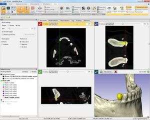 Segmentation of tooth from patient-specific data | |
| Developer(s) | Synopsys |
|---|---|
| Stable release |
N-2018.03
/ 12 March 2018 |
| Operating system | Windows |
| License | Trialware[1] |
| Website |
simpleware |
ScanIP is a 3D image processing and model generation app developed by Synopsys Inc. to visualise, analyse, quantify, segment and export 3D image data from magnetic resonance imaging (MRI), computed tomography (CT), microtomography and other modalities for computer-aided design (CAD), finite element analysis (FEA), computational fluid dynamics (CFD), and 3D printing.[2] The app is used in the life sciences, materials science, nondestructive testing, reverse engineering and petrophysics.
Segmented images can be exported in the STL file format, surface meshes and point clouds, to CAD and 3D printing or, with the FE module, exported as surface/volume meshes directly into leading computer-aided engineering (CAE) solvers.[3] The CAD and NURBS add-on modules can be used to integrate CAD objects into image data, and to convert scan data into NURBS-based models for CAD. The SOLID, FLOW and LAPLACE add-on modules can be used to calculate effective material properties from scanned samples using homogenisation techniques.
Application areas
Life sciences and design of medical and dental implants
ScanIP generates high-quality 3D models from image data suitable for a wide range of design and simulation applications related to the life sciences. Image data from sources like MRI and CT can be visualised, analysed, segmented and quantified, before being exported as CAD, CAE and 3D printing models. Different tissues, bones and other parts of the body can be identified using a wide range of segmentation and processing tools in the software. Options are also available for integrating CAD and image data, enabling medical device research to be conducted into how CAD-designed implants interact with the human body. High-quality CAE models can similarly be used in biomechanics research to simulate movement and the effect of different forces on anatomies. An example of this is the US Naval Research Laboratory/Simpleware head model, generated from high-resolution MRI scans and segmented to create data that can be easily meshed to suit specific finite element (FE) applications, such as head impact and concussion.[4][5]
Applications for the app have include: researching implant position in patient-specific data,[6] statistical shape analysis,[7] and computational fluid dynamics analysis of blood flow in vascular networks.[8] With Simpleware's scripting tools, it is possible to explore the best positioning for hip implants.[9] 3D models can be used to analyse patellofemoral kinematics.[10] Simpleware-generated human body models can be used to simulate the effect of electromagnetic radiation in MRI scanners.[11] Other application areas for models created within Simpleware's software environment include simulating transcranial direct current stimulation,[12] and testing electrode placements for treating epilepsy.[13] In terms of dental research, evaluations of dental implants have been made by integrating CAD objects with patient data and exporting for simulation.[14][15] ScanIP has 510(k) market clearance from the U.S. Food and Drug Administration (FDA) as a Class II Medical Device.[16]
Natural sciences, including paleontology and functional morphology
ScanIP can reconstruct anatomies from scan data for the investigation of different biological and other organic processes within the Natural Sciences. Paleontological uses of ScanIP include the reconstruction of dinosaur skeletons,[17] while the app has been used to generate a model of a shark head suitable for rapid prototyping and testing of how sharks smell,[18] and for generating STL models of a pseudomorph suitable for 3D printing.[19] ScanIP has also been used for biomimicry projects for the Eden Project, and for producing artworks inspired by morphology.[20] ScanIP can be used to reverse engineer ant necks to improve understanding of their mechanics.[21]
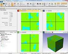
Materials science
ScanIP has extensive applications in different materials sciences where researchers investigate the properties of scanned samples. Scans of composites and other samples can be visualised and processed in ScanIP, enabling multiple phases and porous networks to be explored and analysed.[22] Measurements can be taken, for example, of fractures and cracks, and statistics generated for porosity distribution and other features. ScanIP can be combined with the FE module to generate volume meshes for FE and CFD characterisation of stress or strain distribution, permeability and other material properties.[23] Example applications include fuel cell characterisation,[24] and modelling the effect of porosity on the elastic properties of synthetic graphite.[25]
Petrophysics
ScanIP is used in the oil and gas industry for generating 3D models from scans of core samples and rocks. Image data taken from CT, micro-CT, FIB-SEM and other imaging modalities can be imported and visualised, enabling exploration of pore networks, segmentation of regions of interest, and measurement and quantification of features. Processed data can be exported using the FE module as volume meshes for FEA and CFD in solvers, allowing for insights into fluid-structure-analysis and other geomechanical properties.[26][27]
Nondestructive testing (NDT)
ScanIP can be used to create computational models suitable for detailed visualisation, analysis and export for simulation in CAE solvers. Scanned image data can be easily processed to identify regions of interest, measure defects, quantify statistics such as porosity, and generate CAD and CAE models. Example applications include research into characterising composites,[28] foams,[29] and food.[30]
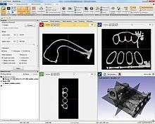
Reverse engineering
With ScanIP, it is possible to reverse engineer legacy parts and other geometries that cannot be accurately created in CAD. Scans of objects can be visualised and processed in ScanIP to learn more about their original design, and exported as FE and CFD models for simulation of physical properties. The app has applications in aerospace, automotive and other fields needing to generate accurate 3D models from scans.[31] Other applications include being able to reverse engineer consumer products in order to analyse their properties,[32] or study how they interact with the human body without the need for invasive testing.
3D printing
ScanIP is capable of generating robust STL files for 3D printing. Files created using ScanIP feature guaranteed watertight triangulations and correct norms, as well as options for volume and topology preserving smoothing. STL files are generated with conforming interfaces, enabling multi-material printing. Internal structures, otherwise known as lattices, can also be added to 3D models of parts in order to reduce weight prior to additive manufacturing.[33] Example applications include the development of patient-specific implants,[34] lattice support structure generation,[35] and 3D organ printing.[36] ScanIP was used to generate STL files of a man's kidney to aid in a procedure at Southampton General Hospital.[37] Lattice techniques have also been used for developing new parts in aerospace, automotive and other industries.[38]
Add-on modules
FE
The FE module generates volume meshes with conforming multi-parts for FEA and CFD. Finite element contacts, node sets and shell elements can be defined, as can boundary conditions for computational fluid dynamics. Material properties can be assigned based on greyscale values or pre-set values. Users can decide between a grid-based or a free meshing approach. Meshes can be exported directly into leading Computer-aided engineering solvers without the need for further processing. The result can be exported to ABAQUS (.inp files), ANSYS (.ans files), COMSOL Multiphysics (.mphtxt files), I-DEAS (.unv files), LS-DYNA (.dyn files), MSC (.out files), FLUENT (.msh files)
CAD
The CAD module allows for the import and interactive positioning of CAD models within image data. The resulting combined models can then be exported as multi-part STLs or, using the FE module, converted automatically into multi-part finite element or CFD meshes. Internal structures can also be added to data to reduce weight whilst maintaining mechanical strength. With CAD, users can avoid having to work with image-based files in CAD-based software. Data can be acquired from ScanIP, IGES (.iges and .igs files), STEP (.step and .stp files), STL (.stl files). The result can be saved in ScanIP files for further processing or exported to STL (.stl files).
NURBS
The NURBS module allows segmented 3D image data to be fitted with non-uniform rational B-splines (NURBS) using automated patch fitting techniques for export as IGES (.iges and .igs files). Autosurface algorithms provide a straightforward route from image data to CAD-ready NURBS models, with options available for contour and curvature detection. CAD geometries can also be inspected prior to export to remove spurious features.
SOLID
The SOLID module calculates the effective stiffness tensor and individual elastic moduli of material samples. Perform numerical homogenisation with a built-in FE solver or derive quick semi-analytical estimates from segmented images.
FLOW
The FLOW module calculates the absolute permeability tensor of porous material samples. Numerical homogenisation is performed using a built-in Stokes solver.
LAPLACE
The LAPLACE module calculates the effective electrical, thermal and molecular properties of materials whose behaviour is governed by the Laplace's equation. Perform numerical homogenisation with a built-in FE solver or derive quick semi-analytical estimates from segmented images.
Import formats
- DICOM
- ACR-NEMA
- Interfile
- Analyze
- MetaImage
- Raw image data (binary, CSV...)
- 2D image stacks (BMP, GIF...)
Export formats
Background image export
- RAW image format
- MetaImage
- Stack of images (BMP, JPG, PNG, TIF)
Segmented image
- Raw image format
- MetaImage
Surface model (triangles)
- STL
- IGES
- ACIS (SAT)
- ANSYS surface mesh
- ABAQUS surface mesh
- Open Inventor
- Point cloud
- MATLAB file surface
Animations
- AVI
- Ogg Theora
- [H.264/MPEG-4 AVC]]
- Windows Media Video Advanced Systems Format
- PNG sequence
2D and 3D screenshot
References
- ↑ "Request a Free 14-day Software Trial". simpleware.com. Synopsys. Retrieved 13 June 2017.
- ↑ Johnson, E., Young, P., 2005. Simpleware: From 3D image to mesh in minutes. CSAR Focus, Edition 14 (Autumn - Winter 2005), 13-15. http://www.csar.cfs.ac.uk/about/csarfocus/focus14/focus14_simpleware.pdf
- ↑ Johnson, E., 2005. Simpleware: From 3D Image to Mesh. The Focus, Issue 39, 2.
- ↑ Wasserman, Shawn (March 11, 2015). "Simulating the Human Head for Safer Helmet Design". Engineering.com. USA. Retrieved March 16, 2015.
- ↑ Marchal, Thierry (February 3, 2015). "Modeling the Risk of Concussion Post Super Bowl 2015". ANSYS-blog.com. USA. Retrieved March 16, 2015.
- ↑ Ali, A.A., Cristofolini, L., Schileo, E., Hu, H., Taddei, F., Kim, R.H., Rullkoetter, P.J., Laz, P.J., 2013. Specimen-Specific Modeling of Hip Fracture Pattern and Repair. Journal of Biomechanics, 47(2), 536-543
- ↑ Wu, J., Wang, Y., Simon, M.A., Sacks, M.S., Brigham, J.C., 2013. A new computational framework for anatomically consistent 3D statistical shape analysis with clinical imaging applications. Computer Methods in Biomechanics and Biomedical Engineering: Imaging & Visualization, 1(1), 13-27.,
- ↑ Cardona, A., Lacroix, D., 2012. COMPUTATIONAL FLUID DYNAMICS OF COMPLEX VASCULAR NETWORK FUNCTIONALITY. Journal of Biomechanics, 45(1), S36.
- ↑ Horner, M., Getting the Right Prosthetic Hip Implant Positioning, ANSYS Blog, 23 October 2014. http://www.ansys-blog.com/prosthetic-hip-implant-positioning/
- ↑ Baldwin, M.A., Clary, C., Maletsky, L.P., Rullkoetter, P.J., 2009. Verification of predicted specimen-specific natural and implanted patellofemoral kinematics during simulated deep knee bend. Journal of Biomechanics, 42, 2341–2348
- ↑ Bonino, P. Electromagnetics in the healthcare industry. Altair HyperWorks Insider. 29 July 2014. http://insider.altairhyperworks.com/electromagnetics-healthcare-industry/
- ↑ Datta, A, Bikson M, Fregni F, (2010), Transcranial direct current stimulation in patients with skull defects and skull plates: High-resolution computational FEM study of factors altering cortical current flow. NeuroImage (52.4). pp. 1268-1278. doi:10.1016/j.neuroimage.2010.04.252
- ↑ Rossi, M., Stebbins, G., Murphy, C., Greene, D, et al (2010) Predicting white matter targets for direct neurostimulation therapy. Epilepsy Research. Volume 91, Issues 2-3. pp. 176-186. doi:10.1016/j.eplepsyres.2010.07.010
- ↑ Queijo, L., Rocha, J., Barreira, L., Ramos, A., San Juan, M., Barbosa, T., 2009. Maxilla bone pre-surgical evaluation aided by 3D models obtained by Rapid Prototyping. Biodental Engineering, 139-144.
- ↑ Hohmann, A., Kober, C., Radtke, T., Young, P., Geiger, M., Boryor, A., Sander, C., Sander F.G., 2008. Feasibility study about finite element simulation of the dental periodontal ligament in vivo. Journal of Medical Biomechanics, 2008(01), 26-30.
- ↑ 510(k) Premarket Notification: ScanIP. U.S. Food and Drug Administration. http://www.accessdata.fda.gov/scripts/cdrh/cfdocs/cfpmn/pmn.cfm?ID=K142779
- ↑ Manning, P.L.; Margetts, L.; Johnson, M.R.; Withers, P.J.; Sellers, W.I.; Falkingham, P.L.; Mummery, P.M.; Barrett, P.M.; Raymont, D.R.; et al. (2009). "Biomechanics of dromaeosaurid dinosaur claws: Application of X-ray microtomography, nanoindentation, and finite element analysis". The Anatomical Record. 292 (9): 1397–1405. doi:10.1002/ar.20986.
- ↑ Abel, R.L., Maclaine, J.S., Cotton, R., Bui Xuan, V., Nickels, T.B., Clark, T.H., Wang, Z., Cox, J.P.L., 2010. Functional morphology of the nasal region of a hammerhead shark. Comparative Biochemistry and Physiology, Part A, 155, 464–475.
- ↑ u-VIS case study: Pseudomorph modelling. University of Southampton. http://www.southampton.ac.uk/~muvis/case_studies/04_Pseudomorph_modelling.html
- ↑ Simpleware will contribute to Biomimicry display. CFDFea.com. 15 June 2005.http://www.cfdfea.com/2005/06/simpleware-joins-the-eden-project-in-public-awareness-scheme/
- ↑ Nguyen, V.N., Lilly, B.W., & Castro, C.E., 2012. Reverse Engineering the Structure and Function of the Allegheny Mound Ant Neck. In: ASME 2012 International Mechanical Engineering Congress & Exposition, 9–15 November 2012 Houston, Texas, USA.
- ↑ Alghamdi, A., Khan, A., Mummery, P., & Sheikh, M., 2013. The characterisation and modelling of manufacturing porosity of a 2-D carbon/carbon composite. Journal of Composite Materials. http://jcm.sagepub.com/content/early/2013/09/13/0021998313502739.abstract
- ↑ Coleri, E., & Harvey, J.T., 2013. A fully heterogeneous viscoelastic finite element model for full-scale accelerated pavement testing. Construction and Building Materials, 43, 14-30.
- ↑ Clague, R., Shearing, P.R., Lee, P.D., Zhang, Z., Brett, D.J.L., Marquis, A.J., Brandon, N.P., 2011. Stress analysis of solid oxide fuel cell anode microstructure reconstructed from focused ion beam tomography. Journal of Power Sources, 196(21), 9018-9021
- ↑ Sowa, G., Paul, R., Smith, R., 2013. Modeling the Effect of Porosity on the Elastic Properties of Synthetic Graphite Using CT Scans and the Finite Element Method. In: COMSOL Conference Boston 2013, 9–11 October 2013 Boston.
- ↑ Blaheta, R., Kohut, R., Kolcun, A., Souček, K., Staš, L., 2013. Micromechanics of geocomposites: CT images and FEM simulations. In: Kwaśniewski, M., Łydżba, D. (Eds.), 2013. Rock Mechanics for Resources, Energy and Environment, pp. 399-404. London : CRC Press Taylor & Francis Group.
- ↑ Saxena, N., Mavko, G., Dvorkin, J., Young, P., Richards, S., Mukerji, T., 2013. Digital Simulations and Rock Physics Modeling of Bituminous Sand. In: Stanford Rock Physics & Borehole Geophysics Annual Meeting, 19–21 June 2013 Menlo Park.
- ↑ Alghamdi, A., Khan, A., Mummery, P., Sheikh, M., 2013. The characterisation and modelling of manufacturing porosity of a 2-D carbon/carbon composite. Journal of Composite Materials..
- ↑ Abdul-Aziz, A., Abumeri, G., Garg, M., Young, P.G., 2008. Structural Evaluation of a Nickel Base Super Alloy Metal Foam Via NDE and Finite Element. In: Smart Structures and Materials & Nondestructive Evaluation, 9–13 March 2008 San Diego. Bellingham: SPIE.
- ↑ Said, R., Schüller, R., Young, P., Aastveit, A., Egelandsdal, B., 2007. Simulation of salt diffusion in a pork (bacon) side using 3D imaging. In: Petit, J.-M., Squalli, O. eds. Proceedings of the European COMSOL Conference 2007, 23–24 October 2007 Grenoble. Grenoble: COMSOL France, Vol 2, 876-881.
- ↑ Wang, W., & Genc, K., 2012. Multiphysics Software Applications in Reverse Engineering. In: COMSOL Conference 2012, 3–5 October 2012 Boston, USA.
- ↑ Lin, S.Y., Su, K.C., Chang, C.H., 2013. Reverse Engineering of CT-based Rocker Sole Model—Finite Element Analysis. In: International Conference on Orange Technologies, 12–16 March 2013 Tainan.
- ↑ Young, P., Raymont, D., Hao, L, Cotton, R., 2010. Internal Micro-Architecture Generation. In: TCT Additive Manufacturing Conference, 19–20 October 2010 Coventry.
- ↑ O'Reilly, S., 2012. 3D printing and medical-device development. Medical Design, May 2012 12(4), 40-43.
- ↑ Hussein, A., Hao, L., Yan, C., Everson, R., Young, P., 2013. Advanced lattice support structures for metal additive manufacturing. Journal of Materials Processing Technology, 213(7), 1019–1026
- ↑ Kang, H.-W., Kengla, C., Lee, S.J., Yoo, J.J., & Atala, A., 2014. 3-D organ printing technologies for tissue engineering applications. In: Narayan, R. (Ed.), 2014. Rapid Prototyping of Biomaterials. Principles and Applications., pp. 236-253
- ↑ BBC News (January 14, 2015). "Southampton hospital patient's 3D kidney model used in op". BBC News. UK. Retrieved February 11, 2015.
- ↑ Griffiths, Laura. "Lattice structures - simplified". TCT Personalize. Retrieved 3 July 2015.