RS-485
| TIA-485-A (Revision of EIA-485) | |
|---|---|
| Standard | ANSI/TIA/EIA-485-A-1998 Approved: March 3, 1998 Reaffirmed: March 28, 2003 |
| Physical media | Balanced interconnecting cable |
| Network topology | Point-to-point, multi-dropped, multi-point |
| Maximum devices | At least 32 unit loads |
| Maximum distance | Not specified |
| Mode of operation | Different receiver levels: binary 1 (OFF) (Voa–Vob < −200 mV) binary 0 (ON) (Voa–Vob > +200 mV) |
| Available signals | A, B, C |
| Connector types | Not specified |
RS-485, also known as TIA-485(-A), EIA-485, is a standard defining the electrical characteristics of drivers and receivers for use in serial communications systems. Electrical signaling is balanced, and multipoint systems are supported. The standard is jointly published by the Telecommunications Industry Association and Electronic Industries Alliance (TIA/EIA). Digital communications networks implementing the standard can be used effectively over long distances and in electrically noisy environments. Multiple receivers may be connected to such a network in a linear, multidrop bus. These characteristics make RS-485 useful in industrial control systems and similar applications.
Overview
RS-485 supports inexpensive local networks and multidrop communications links, using the same differential signaling over twisted pair as RS-422. It is generally accepted that RS-485 can be used with data rates up to 10 Mbit/s[lower-alpha 1] or, at lower speeds, distances up to 1,200 m (4,000 ft).[2] As a rule of thumb, the speed in bit/s multiplied by the length in metres should not exceed 108. Thus a 50-meter cable should not signal faster than 2 Mbit/s.[3]
In contrast to RS-422, which has a driver circuit which cannot be switched off, RS-485 drivers use three-state logic allowing individual transmitters to be deactivated. This allows RS-485 to implement linear bus topologies using only two wires. The equipment located along a set of RS-485 wires are interchangeably called nodes, stations or devices.[4] The recommended arrangement of the wires is as a connected series of point-to-point (multidropped) nodes, i.e. a line or bus, not a star, ring, or multiply connected network. Star and ring topologies are not recommended because of signal reflections or excessively low or high termination impedance. If a star configuration is unavoidable, special RS-485 repeaters are available which bidirectionally listen for data on each span and then retransmit the data onto all other spans.
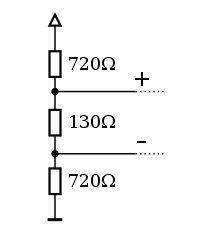
Ideally, the two ends of the cable will have a termination resistor connected across the two wires. Without termination resistors, signal reflections off the unterminated end of the cable can cause data corruption. Termination resistors also reduce electrical noise sensitivity due to the lower impedance. The value of each termination resistor should be equal to the cable characteristic impedance (typically, 120 ohms for twisted pairs). The termination also includes pull up and pull down resistors to establish fail-safe bias for each data wire for the case when the lines are not being driven by any device. This way, the lines will be biased to known voltages and nodes will not interpret the noise from undriven lines as actual data; without biasing resistors, the data lines float in such a way that electrical noise sensitivity is greatest when all device stations are silent or unpowered.[5]
Standard
The EIA once labeled all its standards with the prefix "RS" (Recommended Standard), but the EIA-TIA officially replaced "RS" with "EIA/TIA" to help identify the origin of its standards.[6] The EIA has officially disbanded and the standard is now maintained by the TIA as TIA-485, but engineers and applications guides continue to use the RS-485 designation.
RS-485 only specifies electrical characteristics of the generator and the receiver. It does not specify or recommend any communications protocol, only the physical layer. Other standards define the protocols for communication over an RS-485 link. The foreword to the standard recommends The Telecommunications Systems Bulletin TSB-89 which contains application guidelines, including data signaling rate vs. cable length, stub length, and configurations.
Section 4 defines the electrical characteristics of the generator (transmitter or driver), receiver, transceiver, and system. These characteristics include: definition of a unit load, voltage ranges, open circuit voltages, thresholds, and transient tolerance. It also defines three generator interface points (signal lines); "A", "B" and "C". The data is transmitted on "A" and "B". "C" is a ground reference. This section also defines the logic states 1 (off) and 0 (on), by the polarity between A and B terminals. If A is negative with respect to B, the state is binary 1. The reversed polarity (A +, B −) is binary 0. The standard does not assign any logic function to the two states.
Master-slave arrangement
Often in a master-slave arrangement when one device, the master, initiates all communication activity, the master device itself provides the bias and not the slave devices. In this configuration, the master device is typically centrally located along the set of RS-485 wires, with two slave devices located at the physical end of the wires providing termination. The master device itself could provide termination if it were located at a physical end of the wires, but that is generally regarded as a bad topology design[7] as the master operates optimally when located at a halfway point between the slave devices, thereby maximizing signal strength and therefore line distance and speed. Applying the bias at multiple node locations could possibly cause a violation of the RS-485 specification and cause communications to malfunction.
Full duplex operation
RS-485, like RS-422, can be made full-duplex by using four wires. Since RS-485 is a multi-point specification, however, this is not necessary in many cases. RS-485 and RS-422 can interoperate with certain restrictions.
Converters between RS-485 and other formats are available to allow a personal computer to communicate with remote devices. By using "Repeaters" and "Multi-Repeaters" very large RS-485 networks can be formed. TSB-89A, The Application Guidelines for TIA/EIA-485-A has one diagram called "Star Configuration. Not recommended." Using an RS-485 "Multi-Repeater" can allow for "Star Configurations" with "Home Runs" (or multi-drop) connections similar to Ethernet Hub/Star implementations (with greater distances). Hub/Star systems (with "Multi-Repeaters") allow for very maintainable systems, without violating any of the RS-485 specifications. Repeaters can also be used to extend the distance or number of nodes on a network.
Applications
RS-485 signals are used in a wide range of computer and automation systems. In a computer system, SCSI-2 and SCSI-3 may use this specification to implement the physical layer for data transmission between a controller and a disk drive. RS-485 is used for low-speed data communications in commercial aircraft cabins' vehicle bus. It requires minimal wiring, and can share the wiring among several seats, reducing weight.
RS-485 is used as the physical layer underlying many standard and proprietary automation protocols used to implement Industrial Control Systems, including the most common versions of Modbus and Profibus. DH 485 is a proprietary communications protocol used by Allen-Bradley in their line of industrial control units. Utilizing a series of dedicated interface devices, it allows PCs and industrial controllers to communicate in a local area network utilizing a token passing medium access control.[8] These are used in programmable logic controllers and on factory floors. Since it is differential, it resists electromagnetic interference from motors and welding equipment.
In theatre and performance venues RS-485 networks are used to control lighting and other systems using the DMX512 protocol.
RS-485 is also used in building automation as the simple bus wiring and long cable length is ideal for joining remote devices. It may be used to control video surveillance systems or to interconnect security control panels and devices such as access control card readers.
It is also used in model railway: the layout is controlled by a command station using Digital Command Control (DCC). The external interface to the DCC command station is often RS-485 used by hand-held controllers[9] or for controlling the layout in a network/PC environment.[10] Connectors in this case are 8P8C / RJ45.
Protocols
RS-485 does not define a protocol; merely an electrical interface. Although many applications use RS-485 signal levels, the speed, format, and protocol of the data transmission are not specified by RS-485. Interoperability of even similar devices from different manufacturers is not assured by compliance with the signal levels alone.
The most common protocol in use is asynchronous serial communication, but others are also in use e.g. Simple Sensor Interface protocol.
Signals
The RS-485 differential line consists of two pins:
- A, which is low for logic 1 and high for logic 0.
- B, which is high for logic 1 and low for logic 0.
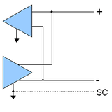
An optional, third pin may be present (the TIA standard (ANSI/TIA/EIA-485-A, page 15, A.4.1) requires the presence of a common return path between all circuit grounds along the balanced line for proper operation) :
- SC aka G aka reference pin. (Discussed further below.)
The RS-485 standard states (paraphrased):
- For a MARK (logic 1), the driver's A terminal is negative relative to the B terminal.
- For a SPACE (logic 0), the driver's A terminal is positive relative to the B terminal.
The truth tables of most popular devices, starting with the SN75176, show the output signals inverted. This has caused much confusion since, with most device manufacturers following the SN75176's lead.
These names are all in use on various equipment, but the actual standard released by EIA only uses the names A and B. The B line is positive (compared to A) when data is 1. However, due to the ambiguous standard (which refers to the A line as "non-inverting"), there is much confusion about which is which. The RS-485 signaling specification, confusingly, says that signal A is the non-inverting pin and signal B is the inverting pin.[11] This is in accordance with the A/B naming used, incorrectly, by most differential transceiver manufacturers, including, among others:
- Texas Instruments, as seen in their application handbook on EIA-422/485 communications (A=non-inverting, B=inverting)
- Intersil, as seen in their data sheet for the ISL4489 transceiver[12]
- Maxim, as seen in their data sheet for the MAX483 transceiver[13]
- Linear Technology, as seen in their datasheet for the LTC2850, LTC2851, LTC2852[14]
- Analog Devices, as seen in their datasheet for the ADM3483, ADM3485, ADM3488, ADM3490, ADM3491[15]
- FTDI, as seen in their datasheet for the USB-RS485-WE-1800-BT[16]
These manufacturers are all incorrect (but consistent), and their practice is in widespread use, so care must be taken when using A/B naming.
A common de-facto standard is the use of:
- TX+/RX+ or D+ as alternative for B (high for MARK i.e. idle)
- TX-/RX- or D- as alternative for A (low for MARK i.e. idle)
With Modbus, BACnet and Profibus, A/B labeling refers A as the negative green wire and B as the positive red wire, in the definition of the D-sub connector and M12 circular connector, as can be seen in Profibus guides.[17][18] As long as standard excludes logic function of the generator or receiver,[19] it would make sense A (green, negative) is higher than B (red, positive). However this contradicts the facts that an idle mark state is a logical one and the termination polarization puts B at a higher voltage in Profibus guidelines.[20] That so-called 'Pesky Polarity' problem [21] raised confusion which made authors think A is inverting within the TIA-485-A standard itself [22] and advise to swap what is A and B in drivers and line labeling as can be read in a section of an application bulletin: "Design Consideration #3: Sometimes Bus Node A Isn’t Really Bus Node A".[23] It is now a common design decision to make this inversion which involves the following polarity chain: UART/MCU idle => TTL/CMOS = +5V => Line B voltage > Line A voltage, implying A, the green wire, is indeed connected to the driver inverting signal, as seen in a whitepaper.[24]
RS-485 does not specify any connector or pinout. Circuits may be terminated on screw terminals, D-subminiature connectors, or other types of connectors.
The standard does not discuss cable shielding, but makes some recommendations on preferred methods of interconnecting the signal reference common and equipment case grounds.
Common-mode
In addition to the A and B connections, the EIA standard also specifies a third interconnection point called SC, which is the common signal reference ground. This connection may be used to limit the common-mode signal that can be impressed on the receiver inputs. This third signal is the reference potential used by the transceiver to measure the A and B voltages.
The allowable common-mode voltage is in the range -7V to +12V, i.e. +/-7V on top of the 0-5V signal range. Failure to stay within this range will result in, at best, signal corruption, and, at worst, device destruction. However care must also be taken that an SC connection, especially over long cable runs, does not result in an attempt to connect disparate grounds together - it is wise to add some current-limiting to the SC cable. Grounds between buildings may vary by a small voltage, but with a very low impedance and hence the possibility of catastrophic currents - enough to melt signal cables, PCB traces, and transceiver devices.
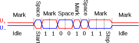
Waveform example
The diagram below shows potentials of the '+' and '−' pins of an RS-485 line during transmission of one byte (0xD3, least significant bit first) of data using an asynchronous start-stop method.
See also
Notes
- ↑ Under some conditions it can be used up to data transmission speeds of 64 Mbit/s.[1]
References
- ↑ http://www.ti.com/lit/sg/slyt484a/slyt484a.pdf
- ↑ https://www.maximintegrated.com/en/app-notes/index.mvp/id/3884
- ↑ Soltero, Manny; Zhang, Jing; Cockril, Chris; Zhang, Kevin; Kinnaird, Clark; Kugelstadt, Thomas (May 2010) [2002]. RS-422 and RS-485 Standards Overview and System Configurations, Application Report (pdf). Texas Instruments (Technical report). SLLA070D.
- ↑ Electronic Industries Association (1983). Electrical Characteristics of Generators and Receivers for Use in Balanced Multipoint Systems. EIA Standard RS-485. OCLC 10728525.
- ↑ "DS3695,DS3695A,DS3695AT,DS3695T,DS96172, DS96174,DS96F172MQML,DS96F174MQML: Application Note 847 FAILSAFE Biasing of Differential Buses (Literature Number: SNLA031)" (PDF). Texas Instruments. 2011.
- ↑ "Trim-the-fat-off-RS-485-designs". EE Times. 2000.
- ↑ Thomas, George (March–April 2008). "Examining the BACnet MS/TP Physical Layer" (PDF). the Extension. Contemporary Control Systems, Inc. 9 (2).
- ↑ "DH-485 Industrial Local Area Network Overview". Rockwell Automation. Retrieved 10 September 2010.
- ↑ lenzusa.com, XpressNET FAQ, accessed July 26, 2015
- ↑ bidib.org, "BiDiBus, a Highspeed-Bus for model-railways", accessed July 26, 2015.
- ↑ "Polarity conventions" (PDF). Texas Instruments. 2003.
- ↑ "Data Sheet FN6074.3: ±15kV ESD Protected, 1/8 Unit Load, 5V, Low Power, High Speed and Slew Rate Limited, Full Duplex, RS-485/RS-422 Transceivers" (PDF). Intersil Corporation. 28 April 2006.
- ↑ "Data Sheet 19-0122 – MAX481/MAX483/MAX485/MAX487–MAX491/MAX1487: Low-Power, Slew-Rate-Limited RS-485/RS-422 Transceivers" (PDF). Maxim Integrated. September 2009.
- ↑ "LTC2850/LTC2851/LTC2852 3.3V 20Mbps RS485/RS422 Transceivers" (PDF). Linear Technology Corporation. 2007.
- ↑ "ADM3483/ADM3485/ADM3488/ADM3490/ADM3491 (Rev. E)" (PDF). Analog Devices, Inc. 22 November 2011.
- ↑ "USB to RS485 Serial Converter Cable Datasheet" (PDF). Future Technology Devices International Ltd. 27 May 2010.
- ↑ "Profibus Interconnection Guideline (PDF)". 1.4. P International. January 2007. p. 7. (Registration required (help)).
- ↑ "SIMATIC NET Profibus Network Manual (PDF)" (PDF). Siemens. April 2009. p. 157.
- ↑ "RS-485 Technical Manual, TIA-485 section". Wikibooks.
- ↑ "Profibus Interconnection Guideline (PDF)". 1.4. P International. January 2007. p. 8. (Registration required (help)).
- ↑ "RS-485 Technical Manual, That Pesky Polarity". Wikibooks.
- ↑ "RS485 Polarity Issues". Chipkins Automation Systems.
- ↑ "Application Bulletin AB-19, Profibus Compliance: A Hardware Design Guide" (PDF). NVE Corporation. 2010.
- ↑ "White paper: Polarities for Differential Pair Signals". Advantech B+B SmartWorx.
External links
| Wikibooks has a book on the topic of: Serial Programming:RS-485 Technical Manual |
- "TUTORIAL 763: Guidelines for Proper Wiring of an RS-485 (TIA/EIA-485-A) Network". Maxim Integrated. 19 November 2001.
- "RS232 to RS485 cable pinout". Pinouts.ru. 7 October 2012.
- "RS485 serial information". Lammert Bies. August 2012. Retrieved 12 November 2012. – Practical information about implementing RS485
- Scordino, Claudio (22 November 2011). "Linux RS485 support". Retrieved 12 November 2012. – Implementation of RS485 standard in the Linux OS
- Marais, Hein (2008). "APPLICATION NOTE AN-960: RS-485/RS-422 Circuit Implementation Guide" (PDF). Analog Devices.
| General | |
|---|---|
| Standards |
|
| Storage | |
| Peripheral | |
| Audio | |
| Portable | |
| Embedded | |
Interfaces are listed by their speed in the (roughly) ascending order, so the interface at the end of each section should be the fastest. | |