Programmable logic controller
A Programmable Logic Controller (PLC) is an electronic device which receives different input parameter in electronic form(Signal), processes the inputs as per the program/logic loaded in it and gives output parameters in electronic form(Signal).
| Part of a series of articles on |
| Manufacturing |
|---|
 |
| Manufacturing methods |
| Improvement methods |
| Information and communication |
| Process control |
A programmable logic controller (PLC) or programmable controller is an industrial digital computer which has been ruggedized and adapted for the control of manufacturing processes, such as assembly lines, or robotic devices, or any activity that requires high reliability control and ease of programming and process fault diagnosis.
They were first developed in the automobile manufacturing industry to provide flexible, ruggedized and easily programmable controllers to replace hard-wired relays, timers and sequencers. Since then they have been widely adopted as high-reliability automation controllers suitable for harsh environments. A PLC is an example of a "hard" real-time system since output results must be produced in response to input conditions within a limited time, otherwise unintended operation will result.
Overview
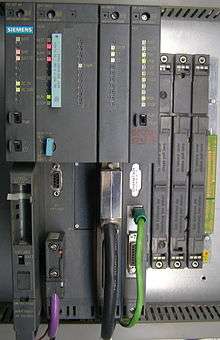
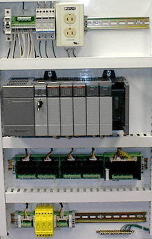
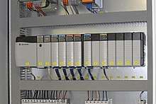
PLCs can range from small "building brick" devices with tens of inputs and outputs (I/O), in a housing integral with the processor, to large rack-mounted modular devices with a count of thousands of I/O, and which are often networked to other PLC and SCADA systems.
They can be designed for multiple arrangements of digital and analog I/O, extended temperature ranges, immunity to electrical noise, and resistance to vibration and impact. Programs to control machine operation are typically stored in battery-backed-up or non-volatile memory.
It was from the automotive industry in the USA that the PLC was born. Before the PLC, control, sequencing, and safety interlock logic for manufacturing automobiles was mainly composed of relays, cam timers, drum sequencers, and dedicated closed-loop controllers. Since these could number in the hundreds or even thousands, the process for updating such facilities for the yearly model change-over was very time consuming and expensive, as electricians needed to individually rewire the relays to change their operational characteristics.
When digital computers became available, being general-purpose programmable devices, they were soon applied to control sequential and combinatorial logic in industrial processes. However these early computers required specialist programmers and stringent operating environmental control for temperature, cleanliness, and power quality. To meet these challenges the PLC was developed with several key attributes. It would tolerate the shop-floor environment, it would support discrete (bit-form) input and output in an easily extensible manner, it would not require years of training to use, and it would permit its operation to be monitored. Since many industrial processes have timescales easily addressed by millisecond response times, modern (fast, small, reliable) electronics greatly facilitate building reliable controllers, and performance could be traded off for reliability.[1]
Invention and early development
In 1968 GM Hydra-Matic (the automatic transmission division of General Motors) issued a request for proposals for an electronic replacement for hard-wired relay systems based on a white paper written by engineer Edward R. Clark. The winning proposal came from Bedford Associates of Bedford, Massachusetts. The first PLC, designated the 084 because it was Bedford Associates' eighty-fourth project, was the result.[2] Bedford Associates started a new company dedicated to developing, manufacturing, selling, and servicing this new product: Modicon, which stood for modular digital controller. One of the people who worked on that project was Dick Morley, who is considered to be the "father" of the PLC.[3] The Modicon brand was sold in 1977 to Gould Electronics, later acquired by German Company AEG, and then by French Schneider Electric, the current owner.
One of the very first 084 models built is now on display at Schneider Electric's facility in North Andover, Massachusetts. It was presented to Modicon by GM, when the unit was retired after nearly twenty years of uninterrupted service. Modicon used the 84 moniker at the end of its product range until the 984 made its appearance.
The automotive industry is still one of the largest users of PLCs.
In a parallel development Odo Josef Struger is sometimes known as the "father of the programmable logic controller" as well.[4][5] He was involved in the invention of the Allen-Bradley programmable logic controller (PLC) during 1958 to 1960.[6][7][8] Struger is credited with creating the PLC acronym.[4] Rockwell (Allen-Bradley) became a major programmable logic controller device manufacturer in the United States during the tenure of Struger.[9]
Early PLCs were designed to replace relay logic systems. These PLCs were programmed in "ladder logic", which strongly resembles a schematic diagram of relay logic. This program notation was chosen to reduce training demands for the existing technicians. Other early PLCs used a form of instruction list programming, based on a stack-based logic solver.
Modern PLCs can be programmed in a variety of ways, from the relay-derived ladder logic to programming languages such as specially adapted dialects of BASIC and C. Another method is state logic, a very high-level programming language designed to program PLCs based on state transition diagrams. The majority of PLC systems today adhere to the IEC 61131/3 control systems programming standard that defines 5 languages: Ladder Diagram (LD), Structured Text (ST), Function Block Diagram (FBD), Instruction List (IL) and sequential function chart (SFC).
Many early PLCs did not have accompanying programming terminals that were capable of graphical representation of the logic, and so the logic was instead represented as a series of logic expressions in some version of Boolean format, similar to Boolean algebra. As programming terminals evolved, it became more common for ladder logic to be used, for the aforementioned reasons and because it was a familiar format used for electro-mechanical control panels. Newer formats such as state logic and Function Block (which is similar to the way logic is depicted when using digital integrated logic circuits) exist, but they are still not as popular as ladder logic. A primary reason for this is that PLCs solve the logic in a predictable and repeating sequence, and ladder logic allows the programmer (the person writing the logic) to see any issues with the timing of the logic sequence more easily than would be possible in other formats.
Programming
Early PLCs, up to the mid-1990s, were programmed using proprietary programming panels or special-purpose programming terminals, which often had dedicated function keys representing the various logical elements of PLC programs.[2] Some proprietary programming terminals displayed the elements of PLC programs as graphic symbols, but plain ASCII character representations of contacts, coils, and wires were common. Programs were stored on cassette tape cartridges. Facilities for printing and documentation were minimal due to lack of memory capacity. The oldest PLCs used non-volatile magnetic core memory.
More recently, PLCs are programmed using application software on personal computers, which now represent the logic in graphic form instead of character symbols. The computer is connected to the PLC through USB, Ethernet, RS-232, RS-485, or RS-422 cabling. The programming software allows entry and editing of the ladder-style logic. In some software packages, it is also possible to view and edit the program in function block diagrams, sequence flow charts and structured text. Generally the software provides functions for debugging and troubleshooting the PLC software, for example, by highlighting portions of the logic to show current status during operation or via simulation. The software will upload and download the PLC program, for backup and restoration purposes. In some models of programmable controller, the program is transferred from a personal computer to the PLC through a programming board which writes the program into a removable chip such as an EPROM.
Functionality
The functionality of the PLC has evolved over the years to include sequential relay control, motion control, process control, distributed control systems, and networking. The data handling, storage, processing power, and communication capabilities of some modern PLCs are approximately equivalent to desktop computers. PLC-like programming combined with remote I/O hardware, allow a general-purpose desktop computer to overlap some PLCs in certain applications. Desktop computer controllers have not been generally accepted in heavy industry because the desktop computers run on less stable operating systems than do PLCs, and because the desktop computer hardware is typically not designed to the same levels of tolerance to temperature, humidity, vibration, and longevity as the processors used in PLCs. Operating systems such as Windows do not lend themselves to deterministic logic execution, with the result that the controller may not always respond to changes of input status with the consistency in timing expected from PLCs. Desktop logic applications find use in less critical situations, such as laboratory automation and use in small facilities where the application is less demanding and critical, because they are generally much less expensive than PLCs.
Basic functions
The most basic function of a programmable controller is to emulate the functions of electro-mechanical relays. Discrete inputs are given a unique address, and a PLC instruction can test if the input state is on or off. Just as a series of relay contacts perform a logical AND function, not allowing current to pass unless all the contacts are closed, so a series of "examine if on" instructions will energize its output storage bit if all the input bits are on. Similarly, a parallel set of instructions will perform a logical OR. In an electro-mechanical relay wiring diagram, a group of contacts controlling one coil is called a "rung" of a "ladder diagram ", and this concept is also used to describe PLC logic. Some models of PLC limit the number of series and parallel instructions in one "rung" of logic. The output of each rung sets or clears a storage bit, which may be associated with a physical output address or which may be an "internal coil" with no physical connection. Such internal coils can be used, for example, as a common element in multiple separate rungs. Unlike physical relays, there is usually no limit to the number of times an input, output or internal coil can be referenced in a PLC program.
Some PLCs enforce a strict left-to-right, top-to-bottom execution order for evaluating the rung logic. This is different from electro-mechanical relay contacts, which in a sufficiently complex circuit may either pass current left-to-right or right-to-left, depending on the configuration of surrounding contacts. The elimination of these "sneak paths" is either a bug or a feature, depending on programming style.
More advanced instructions of the PLC may be implemented as functional blocks, which carry out some operation when enabled by a logical input and which produce outputs to signal, for example, completion or errors, while manipulating variable internally that may not correspond to discrete logic.
Timers and counters
The main function of a timer is to keep an output on for a specific length of time. A good example of this is a garage light, where you want power to be cut off after 2 minutes so as to give someone time to go into the house. The three different types of timers that are commonly used are a Delay-OFF, a Delay-ON, and a Delay-ON-Retentive. A Delay-OFF timer activates immediately when turned on, counts down from a programmed time before cutting off, and is cleared when the enabling input is off. A Delay-ON timer is activated by input and starts accumulating time, counts up to a programmed time before cutting off, and is cleared when the enabling input is turned off. A Delay-ON-Retentive timer is activated by input and starts accumulating time, retains the accumulated value even if the (ladder-logic) rung goes false, and can be reset only by a RESET contact.
Counters are primarily used for counting items such as cans going into a box on an assembly line. This is important because once something is filled to its max the item needs to be moved on so something else can be filled. Many companies use counters in PLC's to count boxes, count how many feet of something is covered, or to count how many pallets are on a truck. There are three types of counters, Up counters, Down counters, and Up/Down counters. Up counters count up to the preset value, turn on the CTU (CounT Up output) when the preset value is reached, and are cleared upon receiving a reset. Down counters count down from a preset value, turns on the CTD (CounT Down output) when 0 is reached, and are cleared upon reset. Up/Down counters count up on CU, count down on CD, turn on CTUD (CounT Up/Down output) when the preset value is reached, and cleared on reset.[10]
Programmable logic relay (PLR)
In more recent years, small products called PLRs (programmable logic relays), and also by similar names, have become more common and accepted. These are much like PLCs, and are used in light industry where only a few points of I/O (i.e. a few signals coming in from the real world and a few going out) are needed, and low cost is desired. These small devices are typically made in a common physical size and shape by several manufacturers, and branded by the makers of larger PLCs to fill out their low end product range. Popular names include PICO Controller, NANO PLC, and other names implying very small controllers. Most of these have 8 to 12 discrete inputs, 4 to 8 discrete outputs, and up to 2 analog inputs. Size is usually about 4" wide, 3" high, and 3" deep. Most such devices include a tiny postage-stamp-sized LCD screen for viewing simplified ladder logic (only a very small portion of the program being visible at a given time) and status of I/O points, and typically these screens are accompanied by a 4-way rocker push-button plus four more separate push-buttons, similar to the key buttons on a VCR remote control, and used to navigate and edit the logic. Most have a small plug for connecting via RS-232 or RS-485 to a personal computer so that programmers can use simple Windows applications for programming instead of being forced to use the tiny LCD and push-button set for this purpose. Unlike regular PLCs that are usually modular and greatly expandable, the PLRs are usually not modular or expandable, but their price can be two orders of magnitude less than a PLC, and they still offer robust design and deterministic execution of the logics.
PLC topics
Features

The main difference from most other computing devices is that PLCs are intended-for and therefore tolerant-of more severe conditions (such as dust, moisture, heat, cold), while offering extensive input/output (I/O) to connect the PLC to sensors and actuators. PLC input can include simple digital elements such as limit switches, analog variables from process sensors (such as temperature and pressure), and more complex data such as that from positioning or machine vision systems.[11] PLC output can include elements such as indicator lamps, sirens, electric motors, pneumatic or hydraulic cylinders, magnetic relays, solenoids, or analog outputs. The input/output arrangements may be built into a simple PLC, or the PLC may have external I/O modules attached to a fieldbus or computer network that plugs into the PLC.
Scan time
A PLC program generally loops i.e. executes repeatedly, as long as the controlled system is running. At the start of each execution loop, the status of all physical inputs are copied to an area of memory, sometimes called the "I/O Image Table", which is accessible to the processor. The program then runs from its first instruction rung down to the last rung. It takes some time for the processor of the PLC to evaluate all the rungs and update the I/O image table with the status of outputs.[12] Scan times of a few milliseconds may be encountered for small programs and fast processors, but for older processors and very large programs much longer scan times (on the order of 100 ms) may be encountered. Excessively long scan times may mean the response of the PLC to changing inputs or process conditions is too slow to be useful.
As PLCs became more advanced, methods were developed to change the sequence of ladder execution, and subroutines were implemented.[13] This simplified programming could be used to save scan time for high-speed processes; for example, parts of the program used only for setting up the machine could be segregated from those parts required to operate at higher speed. Newer PLCs now have the option to run the logic program synchronously with the IO scanning. This means that IO is updated in the background and the logic reads and writes values as it's required during the logic scanning.
Special-purpose I/O modules may be used where the scan time of the PLC is too long to allow predictable performance. Precision timing modules, or counter modules for use with shaft encoders, are used where the scan time would be too long to reliably count pulses or detect the sense of rotation of an encoder. This allows even a relatively slow PLC to still interpret the counted values to control a machine, as the accumulation of pulses is done by a dedicated module that is unaffected by the speed of program execution on the PLC.
Process of a scan cycle
There are 5 main steps in a scan cycle:
- Reading inputs
- Executing the program
- Processing communication requests
- Executing CPU diagnostics
- Writing outputs
System scale
A small PLC will have a fixed number of connections built in for inputs and outputs. Typically, expansions are available if the base model has insufficient I/O.
Modular PLCs have a chassis (also called a rack) into which are placed modules with different functions. The processor and selection of I/O modules are customized for the particular application. Several racks can be administered by a single processor, and may have thousands of inputs and outputs. Either a special high speed serial I/O link or comparable communication method is used so that racks can be distributed away from the processor, reducing the wiring costs for large plants. Options are also available to mount I/O points directly to the machine and utilize quick disconnecting cables to sensors and valves, saving time for wiring and replacing components.
User interface
PLCs may need to interact with people for the purpose of configuration, alarm reporting, or everyday control. A human-machine interface (HMI) is employed for this purpose. HMIs are also referred to as man-machine interfaces (MMIs) and graphical user interfaces (GUIs). A simple system may use buttons and lights to interact with the user. Text displays are available as well as graphical touch screens. More complex systems use programming and monitoring software installed on a computer, with the PLC connected via a communication interface.
Communications
Many models of PLCs have built-in communications ports, using RS-232, RS-422, RS-485, or Ethernet. Various protocols are usually included. Many of these protocols are vendor specific.
Most modern PLCs can communicate over a network to some other system, such as a computer running a SCADA (Supervisory Control And Data Acquisition) system or web browser.
PLCs used in larger I/O systems may have peer-to-peer (P2P) communication between processors. This allows separate parts of a complex process to have individual control while allowing the subsystems to co-ordinate over the communication link. These communication links are also often used for HMI devices such as keypads or PC-type workstations.
Formerly, some manufacturers offered dedicated communication modules as an add-on function where the processor had no network connection built-in.
Programming
PLC programs are typically written in a special application on a personal computer, then downloaded by a direct-connection cable or over a network to the PLC. The program is stored in the PLC either in battery-backed-up RAM or some other non- volatile flash memory. Often, a single PLC can be programmed to replace thousands of relays.[14]
Under the IEC 61131-3 standard, PLCs can be programmed using standards-based programming languages. The most commonly used programming language is Ladder diagram (LD) also known as Ladder logic. It uses Contact-Coil logic to make programs like an electrical control diagram. A graphical programming notation called Sequential Function Charts is available on certain programmable controllers. A model which emulated electromechanical control panel devices (such as the contact and coils of relays) which PLCs replaced. This model remains common today.
IEC 61131-3 currently defines five programming languages for programmable control systems: function block diagram (FBD), ladder diagram (LD), structured text (ST; similar to the Pascal programming language), instruction list (IL; similar to assembly language), and sequential function chart (SFC).[15] These techniques emphasize logical organization of operations.[14]
While the fundamental concepts of PLC programming are common to all manufacturers, differences in I/O addressing, memory organization, and instruction sets mean that PLC programs are never perfectly interchangeable between different makers. Even within the same product line of a single manufacturer, different models may not be directly compatible.
Control example shown in ladder diagram
This is a programming example in ladder diagram which shows the control system. A ladder diagram is a method of drawing control circuits which pre-dates PLCs. The ladder diagram resembles the schematic diagram of a system built with electromechanical relays.
As an example, say a facility needs to store water in a tank. The water is drawn from the tank by another system, as needed, and our example system must manage the water level in the tank by controlling the valve that refills the tank. . Shown are:
- Two inputs (from the low and high level switches) represented by contacts of the float switches
- An output to the fill valve, labelled as the fill valve which it controls
- An "internal" contact, representing the output signal to the fill valve which is created in the program.
- A logical control scheme created by the interconnection of these items in software
In ladder diagram, the contact symbols represent the state of bits in processor memory, which corresponds to the state of physical inputs to the system. If a discrete input is energized, the memory bit is a 1, and a "normally open" contact controlled by that bit will pass a logic "true" signal on to the next element of the ladder. Therefore, the contacts in the PLC program that "read" or look at the physical switch contacts in this case must be "opposite" or open in order to return a TRUE for the closed physical switches. Internal status bits, corresponding to the state of discrete outputs, are also available to the program.
In the example, the physical state of the float switch contacts must be considered when choosing "normally open" or "normally closed" symbols in the ladder diagram. The PLC has two discrete inputs from float switches (Low Level and High Level). Both float switches (normally closed) open their contacts when the water level in the tank is above the physical location of the switch.
When the water level is below both switches, the float switch physical contacts are both closed, and a true (logic 1) value is passed to the Fill Valve output. Water begins to fill the tank. The internal "Fill Valve" contact latches the circuit so that even when the "Low Level" contact opens (as the water passes the lower switch), the fill valve remains on. Since the High Level is also normally closed, water continues to flow as the water level remains between the two switch levels. Once the water level rises enough so that the "High Level" switch is off (opened), the PLC will shut the inlet to stop the water from overflowing; this is an example of seal-in (latching) logic. The output is sealed in until a high level condition breaks the circuit. After that the fill valve remains off until the level drops so low that the Low Level switch is activated, and the process repeats again.
| (N.C. physical   (N.C. physical                             |
|   Switch)          Switch)                                  |
|   Low Level       High Level                Fill Valve      |
|------[ ]------|------[ ]----------------------(OUT)---------|
|               |                                             |
|               |                                             |
|               |                                             |
|   Fill Valve  |                                             |
|------[ ]------|                                             |
|                                                             |
|                                                             |
A complete program may contain thousands of rungs, evaluated in sequence. Typically the PLC processor will alternately scan all its inputs and update outputs, then evaluate the ladder logic; input changes during a program scan will not be effective until the next I/O update. A complete program scan may take only a few milliseconds, much faster than changes in the controlled process.
Programmable controllers vary in their capabilities for a "rung" of a ladder diagram. Some only allow a single output bit. There are typically limits to the number of series contacts in line, and the number of branches that can be used. Each element of the rung is evaluated sequentially. If elements change their state during evaluation of a rung, hard-to-diagnose faults can be generated, although sometimes (as above) the technique is useful. Some implementations forced evaluation from left-to-right as displayed and did not allow reverse flow of a logic signal (in multi-branched rungs) to affect the output.
Security
Prior to the discovery of the Stuxnet computer worm in June 2010, security of PLCs received little attention. Modern PLCs generally contain a real-time operating system such as OS-9 or VxWorks, and exploits for these systems exist much as they do for desktop computer operating systems such as Microsoft Windows. PLCs can also be attacked by gaining control of a computer they communicate with.[16]
Simulation
In order to properly understand the operation of a PLC, it is necessary to spend considerable time programming, testing, and debugging PLC programs. PLC systems are inherently expensive, and down-time is often very costly. In addition, if a PLC is programmed incorrectly it can result in lost productivity and dangerous conditions. PLC simulation software such as PLCLogix can save time in the design of automated control applications and can also increase the level of safety associated with equipment since many"what if" scenarios can be tried and tested before the system is activated.[17]
Redundancy
Some special processes need to work permanently with minimum unwanted down time. Therefore, it is necessary to design a system which is fault-tolerant and capable of handling the process with faulty modules. In such cases to increase the system availability in the event of hardware component failure, redundant CPU or I/O modules with the same functionality can be added to hardware configuration for preventing total or partial process shutdown due to hardware failure.
PLC compared with other control systems

PLCs are well adapted to a range of automation tasks. These are typically industrial processes in manufacturing where the cost of developing and maintaining the automation system is high relative to the total cost of the automation, and where changes to the system would be expected during its operational life. PLCs contain input and output devices compatible with industrial pilot devices and controls; little electrical design is required, and the design problem centers on expressing the desired sequence of operations. PLC applications are typically highly customized systems, so the cost of a packaged PLC is low compared to the cost of a specific custom-built controller design. On the other hand, in the case of mass-produced goods, customized control systems are economical. This is due to the lower cost of the components, which can be optimally chosen instead of a "generic" solution, and where the non-recurring engineering charges are spread over thousands or millions of units.
For high volume or very simple fixed automation tasks, different techniques are used. For example, a cheap consumer dishwasher would be controlled by an electromechanical cam timer costing only a few dollars in production quantities.
A microcontroller-based design would be appropriate where hundreds or thousands of units will be produced and so the development cost (design of power supplies, input/output hardware, and necessary testing and certification) can be spread over many sales, and where the end-user would not need to alter the control. Automotive applications are an example; millions of units are built each year, and very few end-users alter the programming of these controllers. However, some specialty vehicles such as transit buses economically use PLCs instead of custom-designed controls, because the volumes are low and the development cost would be uneconomical.[18]
Very complex process control, such as used in the chemical industry, may require algorithms and performance beyond the capability of even high-performance PLCs. Very high-speed or precision controls may also require customized solutions; for example, aircraft flight controls. Single-board computers using semi-customized or fully proprietary hardware may be chosen for very demanding control applications where the high development and maintenance cost can be supported. "Soft PLCs" running on desktop-type computers can interface with industrial I/O hardware while executing programs within a version of commercial operating systems adapted for process control needs.[18]
Programmable controllers are widely used in motion, positioning, or torque control. Some manufacturers produce motion control units to be integrated with PLC so that G-code (involving a CNC machine) can be used to instruct machine movements.[19]
PLCs may include logic for single-variable feedback analog control loop, a proportional, integral, derivative (PID) controller. A PID loop could be used to control the temperature of a manufacturing process, for example. Historically PLCs were usually configured with only a few analog control loops; where processes required hundreds or thousands of loops, a distributed control system (DCS) would instead be used. As PLCs have become more powerful, the boundary between DCS and PLC applications has been blurred.
PLCs have similar functionality as remote terminal units. An RTU, however, usually does not support control algorithms or control loops. As hardware rapidly becomes more powerful and cheaper, RTUs, PLCs, and DCSs are increasingly beginning to overlap in responsibilities, and many vendors sell RTUs with PLC-like features, and vice versa. The industry has standardized on the IEC 61131-3 functional block language for creating programs to run on RTUs and PLCs, although nearly all vendors also offer proprietary alternatives and associated development environments.
In recent years "safety" PLCs have started to become popular, either as standalone models or as functionality and safety-rated hardware added to existing controller architectures (Allen-Bradley Guardlogix, Siemens F-series etc.). These differ from conventional PLC types as being suitable for use in safety-critical applications for which PLCs have traditionally been supplemented with hard-wired safety relays. For example, a safety PLC might be used to control access to a robot cell with trapped-key access, or perhaps to manage the shutdown response to an emergency stop on a conveyor production line. Such PLCs typically have a restricted regular instruction set augmented with safety-specific instructions designed to interface with emergency stops, light screens, and so forth. The flexibility that such systems offer has resulted in rapid growth of demand for these controllers.
Discrete (digital) and analog signals
Discrete (digital) signals behave as binary switches, yielding simply an On or Off signal (1 or 0, True or False, respectively). Push buttons, limit switches, and photoelectric sensors are examples of devices providing a discrete signal. Discrete signals are sent using either voltage or current, where a specific range is designated as On and another as Off. For example, a PLC might use 24 V DC I/O, with values above 22 V DC representing On, values below 2VDC representing Off, and intermediate values undefined. Initially, PLCs had only digital I/O.
Analog signals are like volume controls, with a range of values between zero and full-scale. These are typically interpreted as integer values (counts) by the PLC, with various ranges of accuracy depending on the device and the number of bits available to store the data. As PLCs typically use 16-bit signed binary processors, the integer values are limited between -32,768 and +32,767. Pressure, temperature, flow, and weight are often represented by analog signals. Analog signals can use voltage or current with a magnitude proportional to the value of the process signal. For example, an analog 0 to 10 V or 4-20 mA input would be converted into an integer value of 0 to 32767.
Current inputs are less sensitive to electrical noise (e.g. from welders or electric motor starts) than voltage inputs.
PLCs are at the forefront of manufacturing automation. An engineer working in a manufacturing environment will at least encounter some PLCs, if not use them on a regular basis. Electrical engineering students should have basic knowledge of PLCs because of their widespread use in industrial applications.[20][21][22]
See also
References
- ↑ E. A. Parr, Industrial Control Handbook, Industrial Press Inc., 1999 ISBN 0-8311-3085-7
- 1 2 M. A. Laughton, D. J. Warne (ed), Electrical Engineer's Reference book, 16th edition,Newnes, 2003 Chapter 16 Programmable Controller
- ↑ "The father of invention: Dick Morley looks back on the 40th anniversary of the PLC". Manufacturing Automation. 12 September 2008.
- 1 2 "Leaders of the Pack". Retrieved 2008-06-20.
- ↑ "Odo Struger, automation expert". Retrieved 2008-06-20.
- ↑ "A-B PLC inventor, Dr. Odo Struger, dies". Archived from the original on 2008-12-03. Retrieved 2008-06-20.
- ↑ Brier, Steven E. (1998-12-27). "O. Struger, 67, A Pioneer In Automation". The New York Times. Retrieved 2008-07-27.
Dr. Odo J. Struger, who invented the programmable logic controller, which makes possible modern factory automation, amusement park rides and lavish stage effects in Broadway productions, died on December 8 in Cleveland. He was 67.
- ↑ Anzovin, p. 100, item # 2189. Programmable logic controller was invented by the Austrian-born American engineer Odo J. Struger in 1958-60 at the Allen-Bradley company in Milwaukee, WI, USA. A programmable logic controller, or PLC, is a simple electronic device that allows precise numerical control of machinery. It is widely used to control everything from washing machines to roller coaster to automated manufacturing equipment.
- ↑ "A short history of Automation growth". Retrieved 2008-06-20.
- ↑ Yanik, P. (2017, April 11). Timers and Counters. Cullowhee, NC, United States of America.
- ↑ Harms, Toni M. & Kinner, Russell H. P.E., Enhancing PLC Performance with Vision Systems. 18th Annual ESD/HMI International Programmable Controllers Conference Proceedings, 1989, p. 387-399.
- ↑ Maher, Michael J. Real-Time Control and Communications. 18th Annual ESD/SMI International Programmable Controllers Conference Proceedings, 1989, p. 431-436.
- ↑ Kinner, Russell H., P.E. Designing Programmable Controller Application Programs Using More than One Designer. 14th Annual International Programmable Controllers Conference Proceedings, 1985, p. 97-110.
- 1 2 W. Bolton, Programmable Logic Controllers, Fifth Edition, Newnes, 2009 ISBN 978-1-85617-751-1, Chapter 1
- ↑ Keller, William L Jr. Grafcet, A Functional Chart for Sequential Processes, 14th Annual International Programmable Controllers Conference Proceedings, 1984, p. 71-96.
- ↑ Byres (May 2011). "PLC Security Risk: Controller Operating Systems - Tofino Industrial Security Solution". www.tofinosecurity.com.
- ↑ Lin, Sally; Huang, Xiong (9 August 2011). Advances in Computer Science, Environment, Ecoinformatics, and Education, Part III: International Conference, CSEE 2011, Wuhan, China, August 21-22, 2011. Proceedings. Springer Science & Business Media. p. 15. ISBN 9783642233449 – via Google Books.
- 1 2 Gregory K. McMillan, Douglas M. Considine (ed), Process/Industrial Instruments and Controls Handbook Fifth Edition, McGraw-Hill, 1999 ISBN 0-07-012582-1 Section 3 Controllers
- ↑ Vosough and Vosough (November 2011). "PLC and its Applications" (PDF). International Journal of Multidisciplinary Sciences and Engineering. 2.
- ↑ Erickson, Kelvin T. (1996). "Programmable logic controllers". Institute of Electrical and Electronics Engineers.
- ↑ Iqbal, S. (2008). "Programmable Logic Controllers (PLCs): Workhorse of Industrial Automation". 68-69. IEEEP Journal: 27–31.
- ↑ Petruzella,, Frank D. (2005). "Programmable logic controllers". Tata McGraw-Hill Education.
Further reading
- Daniel Kandray, Programmable Automation Technologies, Industrial Press, 2010 ISBN 978-0-8311-3346-7, Chapter 8 Introduction to Programmable Logic Controllers
- Tom Mejer Antonsen, 2018 "PLC Controls with Structured Text (ST)", ISBN 978-87-4300-241-3, ISBN 978-87-4300-242-0
- Walker, Mark John (2012-09-08). The Programmable Logic Controller: its prehistory, emergence and application (PDF) (PhD thesis). Department of Communication and Systems Faculty of Mathematics, Computing and Technology: The Open University. Archived (PDF) from the original on 2018-06-20. Retrieved 2018-06-20.
External links
| Wikimedia Commons has media related to Programmable logic controller. |
| Wikiversity has learning resources about Programmable logic controller (basics) |
H